

MW27FP1 - diagramas.diagram...
MW27FP1 - diagramas.diagram...
MW27FP1 - diagramas.diagram...

You also want an ePaper? Increase the reach of your titles
YUMPU automatically turns print PDFs into web optimized ePapers that Google loves.
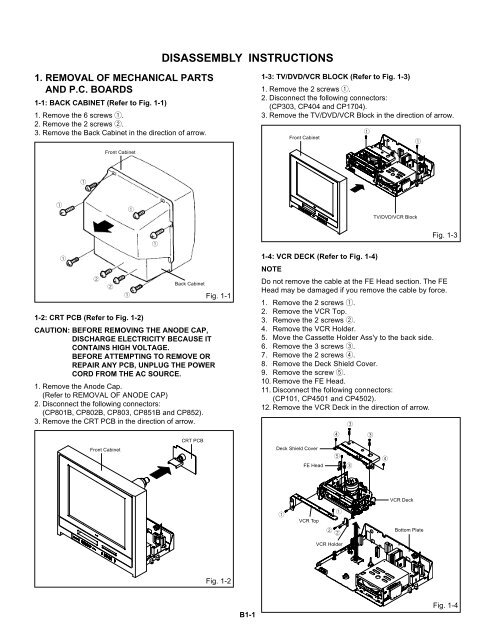
DISASSEMBLY INSTRUCTIONS<br />
1. REMOVAL OF MECHANICAL PARTS<br />
AND P.C. BOARDS<br />
1-1: BACK CABINET (Refer to Fig. 1-1)<br />
1. Remove the 6 screws 1.<br />
2. Remove the 2 screws 2.<br />
3. Remove the Back Cabinet in the direction of arrow.<br />
1-3: TV/DVD/VCR BLOCK (Refer to Fig. 1-3)<br />
1. Remove the 2 screws 1.<br />
2. Disconnect the following connectors:<br />
(CP303, CP404 and CP1704).<br />
3. Remove the TV/DVD/VCR Block in the direction of arrow.<br />
1<br />
Front Cabinet<br />
1<br />
Front Cabinet<br />
1<br />
1<br />
1<br />
TV/DVD/VCR Block<br />
1<br />
2<br />
2<br />
1-2: CRT PCB (Refer to Fig. 1-2)<br />
CAUTION: BEFORE REMOVING THE ANODE CAP,<br />
DISCHARGE ELECTRICITY BECAUSE IT<br />
CONTAINS HIGH VOLTAGE.<br />
BEFORE ATTEMPTING TO REMOVE OR<br />
REPAIR ANY PCB, UNPLUG THE POWER<br />
CORD FROM THE AC SOURCE.<br />
1. Remove the Anode Cap.<br />
(Refer to REMOVAL OF ANODE CAP)<br />
2. Disconnect the following connectors:<br />
(CP801B, CP802B, CP803, CP851B and CP852).<br />
3. Remove the CRT PCB in the direction of arrow.<br />
Front Cabinet<br />
1<br />
1<br />
Back Cabinet<br />
CRT PCB<br />
Fig. 1-1<br />
Fig. 1-3<br />
1-4: VCR DECK (Refer to Fig. 1-4)<br />
NOTE<br />
Do not remove the cable at the FE Head section. The FE<br />
Head may be damaged if you remove the cable by force.<br />
1. Remove the 2 screws 1.<br />
2. Remove the VCR Top.<br />
3. Remove the 2 screws 2.<br />
4. Remove the VCR Holder.<br />
5. Move the Cassette Holder Ass'y to the back side.<br />
6. Remove the 3 screws 3.<br />
7. Remove the 2 screws 4.<br />
8. Remove the Deck Shield Cover.<br />
9. Remove the screw 5.<br />
10. Remove the FE Head.<br />
11. Disconnect the following connectors:<br />
(CP101, CP4501 and CP4502).<br />
12. Remove the VCR Deck in the direction of arrow.<br />
Deck Shield Cover<br />
FE Head<br />
4<br />
5<br />
3<br />
3<br />
3<br />
4<br />
1<br />
VCR Top<br />
1<br />
2<br />
2<br />
VCR Deck<br />
Bottom Plate<br />
VCR Holder<br />
Fig. 1-2<br />
B1-1<br />
Fig. 1-4


