

MW27FP1 - diagramas.diagram...
MW27FP1 - diagramas.diagram...
MW27FP1 - diagramas.diagram...

Create successful ePaper yourself
Turn your PDF publications into a flip-book with our unique Google optimized e-Paper software.
ELECTRICAL ADJUSTMENTS<br />
3. PURITY AND CONVERGENCE<br />
ADJUSTMENTS<br />
NOTE<br />
1.<br />
2.<br />
3.<br />
3-1: STATIC CONVERGENCE (ROUGH ADJUSTMENT)<br />
1.<br />
2.<br />
3.<br />
4.<br />
5.<br />
6.<br />
7.<br />
8.<br />
Turn the unit on and let it warm up for at least 30<br />
minutes before performing the following adjustments.<br />
Place the CRT surface facing east or west to reduce the<br />
terrestrial magnetism.<br />
Turn ON the unit and demagnetize with a Degauss Coil.<br />
Tighten the screw for the magnet. Refer to the adjusted<br />
CRT for the position. (Refer to Fig. 3-1)<br />
If the deflection yoke and magnet are in one body,<br />
untighten the screw for the body.<br />
Receive the green raster pattern from the color bar<br />
generator.<br />
Slide the deflection yoke until it touches the funnel<br />
side of the CRT.<br />
Adjust center of screen to green, with red and blue on the<br />
sides, using the pair of purity magnets.<br />
Switch the color bar generator from the green raster<br />
pattern to the crosshatch pattern.<br />
Combine red and blue of the 3 color crosshatch pattern<br />
on the center of the screen by adjusting the pair of<br />
4 pole magnets.<br />
Combine red/blue (magenta) and green by adjusting the<br />
pair of 6 pole magnets.<br />
Adjust the crosshatch pattern to change to white<br />
by repeating steps 6 and 7.<br />
3-2: PURITY<br />
NOTE<br />
Adjust after performing adjustments in section 3-1.<br />
1. Receive the green raster pattern from color bar<br />
generator.<br />
2. Adjust the pair of purity magnets to center the<br />
color on the screen.<br />
Adjust the pair of purity magnets so the color at the<br />
ends are equally wide.<br />
3. Move the deflection yoke backward (to neck side)<br />
slowly, and stop it at the position when the whole<br />
screen is green.<br />
4. Confirm red and blue colors.<br />
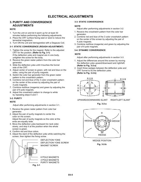
5. Adjust the slant of the deflection yoke while watching the<br />
screen, then tighten the fixing screw.<br />
DEFLECTION YOKE<br />
DEFLECTION YOKE SCREW<br />
MAGNET SCREW<br />
3-3: STATIC CONVERGENCE<br />
NOTE<br />
Adjust after performing adjustments in section 3-2.<br />
1. Receive the crosshatch pattern from the color bar<br />
generator.<br />
2. Combine red and blue of the 3 color crosshatch pattern<br />
on the center of the screen by adjusting the pair of<br />
4 pole magnets.<br />
3. Combine red/blue (magenta) and green by adjusting the<br />
pair of 6 pole magnets.<br />
3-4: DYNAMIC CONVERGENCE<br />
NOTE<br />
Adjust after performing adjustments in section 3-3.<br />
1. Adjust the differences around the screen by moving<br />
the deflection yoke upward/downward and right/left.<br />
(Refer to Fig. 3-2-a)<br />
2. Insert three wedges between the deflection yoke and<br />
CRT funnel to fix the deflection yoke.<br />
(Refer to Fig. 3-2-b)<br />
R<br />
G<br />
B<br />
R G B<br />
WEDGE<br />
R<br />
G<br />
B<br />
UPWARD/DOWNWARD SLANT<br />
Fig. 3-2-a<br />
WEDGE<br />
WEDGE POSITION<br />
Fig. 3-2-b<br />
WEDGE<br />
R G B<br />
RIGHT/LEFT SLANT<br />
6 POLE MAGNETS<br />
4 POLE MAGNETS<br />
PURITY MAGNETS<br />
Fig. 3-1<br />
D3-5


