

MW27FP1 - diagramas.diagram...
MW27FP1 - diagramas.diagram...
MW27FP1 - diagramas.diagram...

You also want an ePaper? Increase the reach of your titles
YUMPU automatically turns print PDFs into web optimized ePapers that Google loves.
DISASSEMBLY INSTRUCTIONS<br />
INSTALLATION<br />
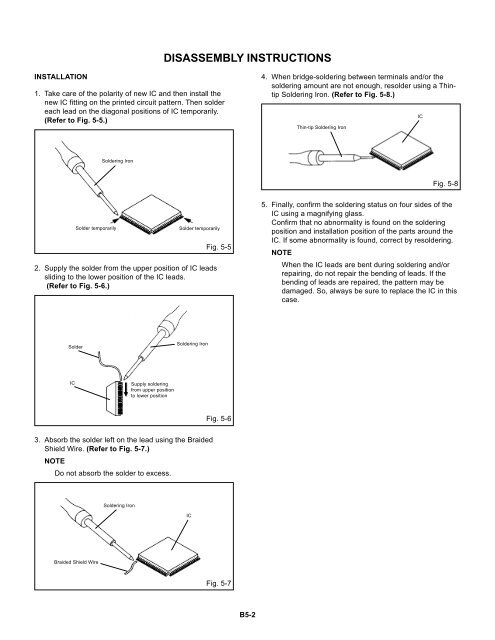
1. Take care of the polarity of new IC and then install the<br />
new IC fitting on the printed circuit pattern. Then solder<br />
each lead on the diagonal positions of IC temporarily.<br />
(Refer to Fig. 5-5.)<br />
4. When bridge-soldering between terminals and/or the<br />
soldering amount are not enough, resolder using a Thintip<br />
Soldering Iron. (Refer to Fig. 5-8.)<br />
Thin-tip Soldering Iron<br />
IC<br />
Soldering Iron<br />
Fig. 5-8<br />
Solder temporarily<br />
Solder temporarily<br />
2. Supply the solder from the upper position of IC leads<br />
sliding to the lower position of the IC leads.<br />
(Refer to Fig. 5-6.)<br />
Fig. 5-5<br />
5. Finally, confirm the soldering status on four sides of the<br />
IC using a magnifying glass.<br />
Confirm that no abnormality is found on the soldering<br />
position and installation position of the parts around the<br />
IC. If some abnormality is found, correct by resoldering.<br />
NOTE<br />
When the IC leads are bent during soldering and/or<br />
repairing, do not repair the bending of leads. If the<br />
bending of leads are repaired, the pattern may be<br />
damaged. So, always be sure to replace the IC in this<br />
case.<br />
Solder<br />
Soldering Iron<br />
IC<br />
Supply soldering<br />
from upper position<br />
to lower position<br />
Fig. 5-6<br />
3. Absorb the solder left on the lead using the Braided<br />
Shield Wire. (Refer to Fig. 5-7.)<br />
NOTE<br />
Do not absorb the solder to excess.<br />
Soldering Iron<br />
IC<br />
Braided Shield Wire<br />
Fig. 5-7<br />
B5-2


