

MW27FP1 - diagramas.diagram...
MW27FP1 - diagramas.diagram...
MW27FP1 - diagramas.diagram...

You also want an ePaper? Increase the reach of your titles
YUMPU automatically turns print PDFs into web optimized ePapers that Google loves.
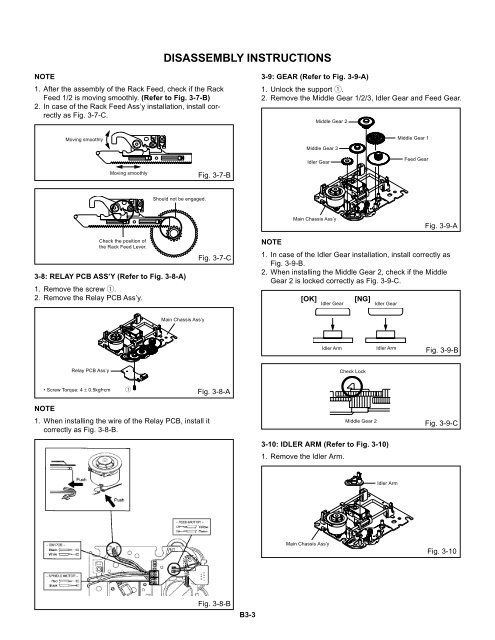
DISASSEMBLY INSTRUCTIONS<br />
NOTE<br />
1. After the assembly of the Rack Feed, check if the Rack<br />
Feed 1/2 is moving smoothly. (Refer to Fig. 3-7-B)<br />
2. In case of the Rack Feed Ass’y installation, install correctly<br />
as Fig. 3-7-C.<br />
3-9: GEAR (Refer to Fig. 3-9-A)<br />
1. Unlock the support 1.<br />
2. Remove the Middle Gear 1/2/3, Idler Gear and Feed Gear.<br />
Middle Gear 2<br />
Moving smoothly<br />
Middle Gear 3<br />
Idler Gear<br />
Middle Gear 1<br />
Feed Gear<br />
Moving smoothly<br />
Fig. 3-7-B<br />
Should not be engaged.<br />
Main Chassis Ass’y<br />
Fig. 3-9-A<br />
Check the position of<br />
the Rack Feed Lever.<br />
3-8: RELAY PCB ASS’Y (Refer to Fig. 3-8-A)<br />
1. Remove the screw 1.<br />
2. Remove the Relay PCB Ass’y.<br />
Fig. 3-7-C<br />
NOTE<br />
1. In case of the Idler Gear installation, install correctly as<br />
Fig. 3-9-B.<br />
2. When installing the Middle Gear 2, check if the Middle<br />
Gear 2 is locked correctly as Fig. 3-9-C.<br />
[OK]<br />
Idler Gear<br />
[NG]<br />
Idler Gear<br />
Main Chassis Ass’y<br />
Idler Arm<br />
Idler Arm<br />
Fig. 3-9-B<br />
Relay PCB Ass’y<br />
Check Lock<br />
• Screw Torque: 4 ± 0.5kgf•cm 1 Fig. 3-8-A<br />
NOTE<br />
1. When installing the wire of the Relay PCB, install it<br />
correctly as Fig. 3-8-B.<br />
Middle Gear 2<br />
3-10: IDLER ARM (Refer to Fig. 3-10)<br />
1. Remove the Idler Arm.<br />
Fig. 3-9-C<br />
Idler Arm<br />
Main Chassis Ass'y<br />
Fig. 3-10<br />
Fig. 3-8-B<br />
B3-3


