

MW27FP1 - diagramas.diagram...
MW27FP1 - diagramas.diagram...
MW27FP1 - diagramas.diagram...

Create successful ePaper yourself
Turn your PDF publications into a flip-book with our unique Google optimized e-Paper software.
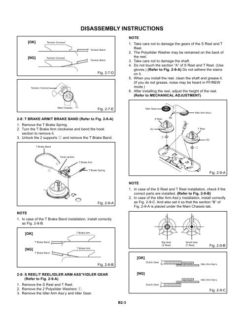
DISASSEMBLY INSTRUCTIONS<br />
[OK]<br />
[NG]<br />
Tension Connect<br />
Tension Connect<br />
Tension Connect<br />
Tension Band<br />
Tension Band<br />
Fig. 2-7-D<br />
NOTE<br />
1.<br />
2.<br />
3.<br />
4.<br />
5.<br />
6.<br />
Take care not to damage the gears of the S Reel and T<br />
Reel.<br />
The Polyslider Washer may be remained on the back of<br />
the reel.<br />
Take care not to damage the shaft.<br />
Do not touch the section “A” of S Reel and T Reel. (Use<br />
gloves.) (Refer to Fig. 2-9-A) Do not adhere the stains<br />
on it.<br />
When you install the reel, clean the shaft and grease it.<br />
(If you do not grease, noise may be heard in FF/REW<br />
mode.)<br />
After installing the reel, adjust the height of the reel.<br />
(Refer to MECHANICAL ADJUSTMENT)<br />
Main Chassis<br />
Fig. 2-7-E<br />
Idler Gear<br />
Idler Arm Ass’y<br />
2-8: T BRAKE ARM/T BRAKE BAND (Refer to Fig. 2-8-A)<br />
S Reel<br />
(B)<br />
1.<br />
2.<br />
3.<br />
Remove the T Brake Spring.<br />
Turn the T Brake Arm clockwise and bend the hook<br />
section to remove it.<br />
Unlock the 2 supports 1 and remove the T Brake Band.<br />
(A)<br />
1<br />
T Reel<br />
(A)<br />
T Brake Band<br />
1<br />
Hook section<br />
1<br />
T Brake Arm<br />
1<br />
T Brake Spring<br />
Fig. 2-9-A<br />
Fig. 2-8-A<br />
NOTE<br />
1. In case of the T Brake Band installation, install correctly<br />
as Fig. 2-8-B.<br />
NOTE<br />
1. In case of the S Reel and T Reel installation, check if the<br />
correct parts are installed. (Refer to Fig. 2-9-B)<br />
2. In case of the Idler Arm Ass’y installation, install correctly<br />
as Fig. 2-9-C. And also set it so that the section “B” of<br />
Fig. 2-9-A is placed under the Main Chassis tab.<br />
[OK]<br />
T Brake Arm<br />
[NG]<br />
T Brake Band<br />
T Brake Band<br />
T Brake Arm<br />
Fig. 2-8-B<br />
[OK]<br />
Clutch Gear<br />
Big Hole<br />
(S Reel)<br />
Small Hole<br />
(T Reel)<br />
Idler Arm Ass’y<br />
Fig. 2-9-B<br />
2-9: S REEL/T REEL/IDLER ARM ASS’Y/IDLER GEAR<br />
(Refer to Fig. 2-9-A)<br />
1.<br />
2.<br />
3.<br />
Remove the S Reel and T Reel.<br />
Remove the 2 Polyslider Washers 1.<br />
Remove the Idler Arm Ass’y and Idler Gear.<br />
[NG]<br />
Clutch Gear<br />
Idler Arm Ass’y<br />
Fig. 2-9-C<br />
B2-3


