

MW27FP1 - diagramas.diagram...
MW27FP1 - diagramas.diagram...
MW27FP1 - diagramas.diagram...

You also want an ePaper? Increase the reach of your titles
YUMPU automatically turns print PDFs into web optimized ePapers that Google loves.
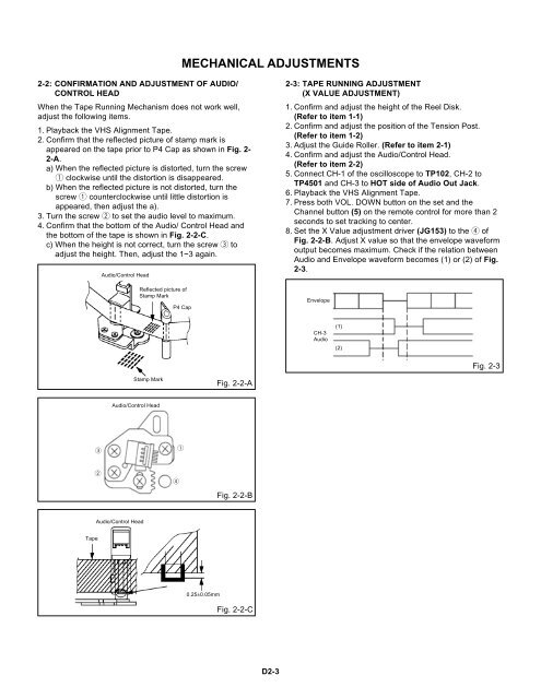
MECHANICAL ADJUSTMENTS<br />
2-2: CONFIRMATION AND ADJUSTMENT OF AUDIO/<br />
CONTROL HEAD<br />
When the Tape Running Mechanism does not work well,<br />
adjust the following items.<br />
1. Playback the VHS Alignment Tape.<br />
2. Confirm that the reflected picture of stamp mark is<br />
appeared on the tape prior to P4 Cap as shown in Fig. 2-<br />
2-A.<br />
a) When the reflected picture is distorted, turn the screw<br />
1 clockwise until the distortion is disappeared.<br />
b) When the reflected picture is not distorted, turn the<br />
screw 1 counterclockwise until little distortion is<br />
appeared, then adjust the a).<br />
3. Turn the screw 2 to set the audio level to maximum.<br />
4. Confirm that the bottom of the Audio/ Control Head and<br />
the bottom of the tape is shown in Fig. 2-2-C.<br />
c) When the height is not correct, turn the screw 3 to<br />
adjust the height. Then, adjust the 1~3 again.<br />
Audio/Control Head<br />
Reflected picture of<br />
Stamp Mark<br />
P4 Cap<br />
2-3: TAPE RUNNING ADJUSTMENT<br />
(X VALUE ADJUSTMENT)<br />
1. Confirm and adjust the height of the Reel Disk.<br />
(Refer to item 1-1)<br />
2. Confirm and adjust the position of the Tension Post.<br />
(Refer to item 1-2)<br />
3. Adjust the Guide Roller. (Refer to item 2-1)<br />
4. Confirm and adjust the Audio/Control Head.<br />
(Refer to item 2-2)<br />
5. Connect CH-1 of the oscilloscope to TP102, CH-2 to<br />
TP4501 and CH-3 to HOT side of Audio Out Jack.<br />
6. Playback the VHS Alignment Tape.<br />
7. Press both VOL. DOWN button on the set and the<br />
Channel button (5) on the remote control for more than 2<br />
seconds to set tracking to center.<br />
8. Set the X Value adjustment driver (JG153) to the 4 of<br />
Fig. 2-2-B. Adjust X value so that the envelope waveform<br />
output becomes maximum. Check if the relation between<br />
Audio and Envelope waveform becomes (1) or (2) of Fig.<br />
2-3.<br />
Envelope<br />
CH-3<br />
Audio<br />
(1)<br />
(2)<br />
Fig. 2-3<br />
Stamp Mark<br />
Fig. 2-2-A<br />
Audio/Control Head<br />
3<br />
1<br />
2<br />
4<br />
Fig. 2-2-B<br />
Audio/Control Head<br />
Tape<br />
0.25±0.05mm<br />
Fig. 2-2-C<br />
D2-3


