

MW27FP1 - diagramas.diagram...
MW27FP1 - diagramas.diagram...
MW27FP1 - diagramas.diagram...

Create successful ePaper yourself
Turn your PDF publications into a flip-book with our unique Google optimized e-Paper software.
DISASSEMBLY INSTRUCTIONS<br />
2. REMOVAL OF VCR DECK PARTS<br />
2-1: TOP BRACKET (Refer to Fig. 2-1)<br />
1.<br />
2.<br />
Extend the 2 supports 1.<br />
Slide the 2 supports 2 and remove the Top Bracket.<br />
NOTE<br />
1. After the installation of the Top Bracket, bend the support<br />
1 so that the Top Bracket is fixed.<br />
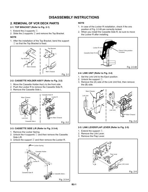
NOTE<br />
1. In case of the Locker R installation, check if the one<br />
position of Fig. 2-3-B are correctly locked.<br />
2. When you install the Cassette Side R, be sure to move<br />
the Locker R after installing.<br />
1<br />
Top Bracket<br />
1<br />
Cassette Side R<br />
Locker R<br />
Check if this position<br />
is locked.<br />
Top Bracket<br />
2<br />
Main Chassis<br />
2<br />
Fig. 2-3-B<br />
1.<br />
2.<br />
3.<br />
Main Chassis<br />
2-2: CASSETTE HOLDER ASS'Y (Refer to Fig. 2-2)<br />
Move the Cassette Holder Ass'y to the front side.<br />
Push the Locker R to remove the Cassette Side R.<br />
Remove the Cassette Side L.<br />
Fig. 2-1<br />
2-4: LINK UNIT (Refer to Fig. 2-4)<br />
1.<br />
2.<br />
3.<br />
Set the Link Unit to the Eject position.<br />
Unlock the support 1.<br />
Remove the (A) side of the Link Unit first, then remove<br />
the (B) side.<br />
Main Chassis<br />
Main Chassis<br />
Cassette Side R<br />
Locker R<br />
Link Unit<br />
(A)<br />
(B)<br />
Link Unit<br />
Link Unit<br />
Cassette Side L<br />
Main Chassis<br />
Fig. 2-2<br />
Main Chassis<br />
Fig. 2-4<br />
2-3: CASSETTE SIDE L/R (Refer to Fig. 2-3-A)<br />
1.<br />
2.<br />
3.<br />
Remove the Locker Spring.<br />
Unlock the 4 supports 1 and then remove the Cassette<br />
Side L/R.<br />
Unlock the support 2 and then remove the Locker R.<br />
2-5: LINK LEVER/FLAP LEVER (Refer to Fig. 2-5)<br />
1.<br />
2.<br />
3.<br />
Extend the support 1.<br />
Remove the Link Lever.<br />
Remove the Flap Lever.<br />
Locker Spring<br />
1<br />
1<br />
2<br />
Cassette Holder<br />
1<br />
Flap Lever<br />
Locker R<br />
1<br />
1<br />
Link Lever<br />
Cassette Side R<br />
Cassette Side L<br />
Fig. 2-5<br />
Fig. 2-3-A<br />
B2-1


