

MW27FP1 - diagramas.diagram...
MW27FP1 - diagramas.diagram...
MW27FP1 - diagramas.diagram...

Create successful ePaper yourself
Turn your PDF publications into a flip-book with our unique Google optimized e-Paper software.
DISASSEMBLY INSTRUCTIONS<br />
3. REMOVAL OF DVD DECK PARTS<br />
NOTE<br />
1. Do not disassemble the DVD DECK PARTS except listed<br />
parts here. Minute adjustments are needed if the disassemble<br />
is done. If the repair is needed except listed parts,<br />
replace the DVD MECHA ASS’Y.<br />
3-1: TRAY (Refer to Fig. 3-1-A)<br />
1. Set the Tray opened. (Refer to the DISC REMOVAL<br />
METHOD AT NO POWER SUPPLY)<br />
2. Unlock the support 1 and remove the Tray.<br />
Rack Loading<br />
Move it to the direction<br />
of the arrow.<br />
1<br />
Main Frame Ass’y<br />
2 3<br />
5<br />
Main Chassis Ass’y<br />
6<br />
4<br />
6 Check Lock<br />
4<br />
5<br />
Tray<br />
1<br />
Main Frame Ass’y<br />
Fig. 3-1-A<br />
NOTE<br />
1. In case of the Tray installation, install them as the circled<br />
section of Fig. 3-1-B so that the each markers are met.<br />
Fig. 3-2-B<br />
3-3: RACK LOADING/MAIN GEAR/ RACK LOADING<br />
SPRING/ RACK L SPRING (Refer to Fig. 3-3)<br />
1. Remove the Rack L Spring.<br />
2. Press down the catcher 1 and slide the Rack Loading.<br />
3. Remove the Rack Loading, Rack Loading Spring and<br />
Main Gear.<br />
Tray<br />
Rack Loading<br />
Rack Loading Spring<br />
Rack L Spring<br />
Main Gear<br />
Main Frame Ass’y<br />
Main Frame Ass’y<br />
Fig. 3-1-B<br />
1<br />
Fig. 3-3<br />
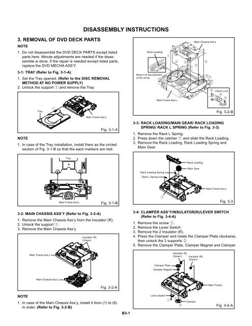
3-2: MAIN CHASSIS ASS’Y (Refer to Fig. 3-2-A)<br />
1. Remove the Main Chassis Ass’y from the Insulator (R).<br />
2. Unlock the support 1.<br />
3. Remove the Main Chassis Ass’y.<br />
Insulator (R)<br />
(Green)<br />
3-4: CLAMPER ASS’Y/INSULATOR(R)/LEVER SWITCH<br />
(Refer to Fig. 3-4-A)<br />
1. Remove the screw 1.<br />
2. Remove the Lever Switch.<br />
3. Remove the 2 Insulator (R).<br />
4. Press the Clamper and rotate the Clamper Plate clockwise,<br />
then unlock the 3 supports 2.<br />
5. Remove the Clamper Plate, Clamper Magnet and Clamper.<br />
Main Frame Ass’y<br />
1<br />
Insulator (R)<br />
(Green)<br />
Insulator (R)<br />
(Green)<br />
Clamper Plate<br />
Clamper Magnet<br />
Main Chassis Ass’y<br />
Fig. 3-2-A<br />
Main Frame<br />
NOTE<br />
1. In case of the Main Chassis Ass’y, install it from (1) to (6)<br />
in order. (Refer to Fig. 3-2-B)<br />
B3-1<br />
Lever Switch<br />
1 2 2<br />
2<br />
Clamper<br />
Fig. 3-4-A


