

MW27FP1 - diagramas.diagram...
MW27FP1 - diagramas.diagram...
MW27FP1 - diagramas.diagram...

Create successful ePaper yourself
Turn your PDF publications into a flip-book with our unique Google optimized e-Paper software.
MECHANICAL ADJUSTMENTS<br />
1. CONFIRMATION AND ADJUSTMENT<br />
Read the following NOTES before starting work.<br />
• Place an object which weighs between 450g~500g on the<br />
Cassette Tape to keep it steady when you want to make<br />
the tape run without the Cassette Holder. (Do not place an<br />
object which weighs over 500g.)<br />
1-1: CONFIRMATION AND ADJUSTMENT OF REEL<br />
DISK HEIGHT<br />
1. Turn on the power and set to the STOP mode.<br />
2. Set the master plane (JG022) and reel disk height<br />
adjustment jig (JG024A) on the mechanism framework,<br />
taking care not to scratch the drum, as shown in Fig. 1-1-<br />
A.<br />
3. While turning the reel and confirm the following points.<br />
Check if the surface "A" of reel disk is lower than the<br />
surface "B" of reel disk height adjustment jig (JG024A)<br />
and is higher than the surface "C". If it is not passed,<br />
place the height adjustment washers and adjust to 10(+2,<br />
-0)mm.<br />
4. Adjust the other reel in the same way.<br />
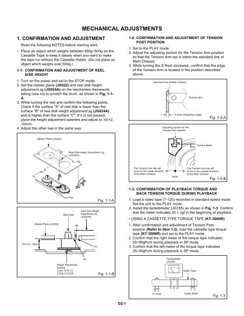
1-2: CONFIRMATION AND ADJUSTMENT OF TENSION<br />
POST POSITION<br />
1. Set to the PLAY mode.<br />
2. Adjust the adjusting section for the Tension Arm position<br />
so that the Tension Arm top is within the standard line of<br />
Main Chassis.<br />
3. While turning the S Reel clockwise, confirm that the edge<br />
of the Tension Arm is located in the position described<br />
above.<br />
Standard line of Main Chassis<br />
Tension Arm<br />
0.5mm (Adjusting range)<br />
Adjusting section for the<br />
Tension Arm position<br />
Fig. 1-2-A<br />
Master Plane (JG022)<br />
Tension Band<br />
Reel Disk Height Adjustment Jig<br />
(JG024A)<br />
The Tension Arm top will<br />
move to the inside direction<br />
of the Main Chassis.<br />
Bend<br />
The Tension Arm top will<br />
move to the outside direction<br />
of the Main Chassis.<br />
Fig. 1-2-B<br />
1-3: CONFIRMATION OF PLAYBACK TORQUE AND<br />
BACK TENSION TORQUE DURING PLAYBACK<br />
Reel Disk<br />
Reel Disk Height<br />
Adjustment Jig<br />
(JG024A)<br />
Fig. 1-1-A<br />
1. Load a video tape (T-120) recorded in standard speed mode.<br />
Set the unit to the PLAY mode.<br />
2. Install the tentelometer (JG185) as shown in Fig. 1-3. Confirm<br />
that the meter indicates 20 ± 2gf in the beginning of playback.<br />
• USING A CASSETTE TYPE TORQUE TAPE (KT-300NR)<br />
10(+0.2, -0)mm<br />
Master Plane (JG022)<br />
(B)<br />
(C)<br />
1. After confirmation and adjustment of Tension Post<br />
position (Refer to item 1-2), load the cassette type torque<br />
tape (KT-300NR) and set to the PLAY mode.<br />
2. Confirm that the right meter of the torque tape indicates<br />
50~90gf•cm during playback in SP mode.<br />
3. Confirm that the left meter of the torque tape indicates<br />
25~40gf•cm during playback in SP mode.<br />
Height Adjustment<br />
Washer<br />
2.6x4.7xT0.13<br />
2.6X4.7xT0.25<br />
(A)<br />
Fig. 1-1-B<br />
Tentelometer<br />
(JG185)<br />
Video Tape<br />
P1 Post<br />
Guide Roller<br />
Fig. 1-3<br />
D2-1


