

MW27FP1 - diagramas.diagram...
MW27FP1 - diagramas.diagram...
MW27FP1 - diagramas.diagram...

You also want an ePaper? Increase the reach of your titles
YUMPU automatically turns print PDFs into web optimized ePapers that Google loves.
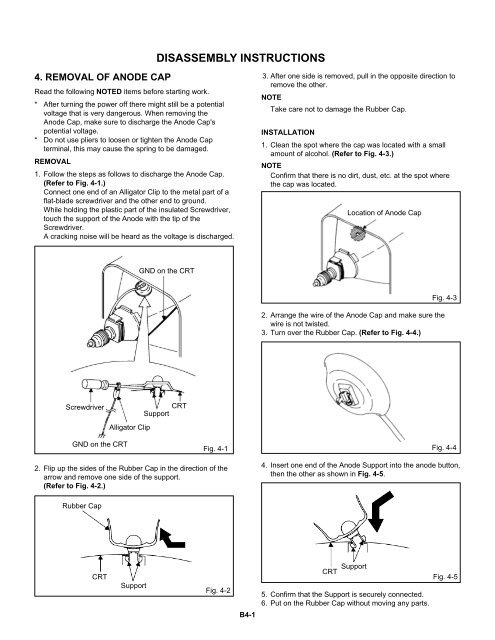
DISASSEMBLY INSTRUCTIONS<br />
4. REMOVAL OF ANODE CAP<br />
Read the following NOTED items before starting work.<br />
* After turning the power off there might still be a potential<br />
voltage that is very dangerous. When removing the<br />
Anode Cap, make sure to discharge the Anode Cap's<br />
potential voltage.<br />
* Do not use pliers to loosen or tighten the Anode Cap<br />
terminal, this may cause the spring to be damaged.<br />
REMOVAL<br />
1. Follow the steps as follows to discharge the Anode Cap.<br />
(Refer to Fig. 4-1.)<br />
Connect one end of an Alligator Clip to the metal part of a<br />
flat-blade screwdriver and the other end to ground.<br />
While holding the plastic part of the insulated Screwdriver,<br />
touch the support of the Anode with the tip of the<br />
Screwdriver.<br />
A cracking noise will be heard as the voltage is discharged.<br />
3. After one side is removed, pull in the opposite direction to<br />
remove the other.<br />
NOTE<br />
Take care not to damage the Rubber Cap.<br />
INSTALLATION<br />
1. Clean the spot where the cap was located with a small<br />
amount of alcohol. (Refer to Fig. 4-3.)<br />
NOTE<br />
Confirm that there is no dirt, dust, etc. at the spot where<br />
the cap was located.<br />
Location of Anode Cap<br />
GND on the CRT<br />
2.<br />
3.<br />
Fig. 4-3<br />
Arrange the wire of the Anode Cap and make sure the<br />
wire is not twisted.<br />
Turn over the Rubber Cap. (Refer to Fig. 4-4.)<br />
Screwdriver<br />
CRT<br />
Support<br />
Alligator Clip<br />
GND on the CRT<br />
Fig. 4-1<br />
Fig. 4-4<br />
2. Flip up the sides of the Rubber Cap in the direction of the<br />
arrow and remove one side of the support.<br />
(Refer to Fig. 4-2.)<br />
4. Insert one end of the Anode Support into the anode button,<br />
then the other as shown in Fig. 4-5.<br />
Rubber Cap<br />
CRT<br />
Support<br />
Fig. 4-2<br />
B4-1<br />
CRT Support Fig. 4-5<br />
5. Confirm that the Support is securely connected.<br />
6. Put on the Rubber Cap without moving any parts.


