guideline and standards for skytem measurements, processing and ...
guideline and standards for skytem measurements, processing and ...
guideline and standards for skytem measurements, processing and ...

Create successful ePaper yourself
Turn your PDF publications into a flip-book with our unique Google optimized e-Paper software.
(February 2011)<br />
APPENDIX 3<br />
DOCUMENTATION OF THE GEOMETRY FILE<br />
The geometry file contains all in<strong>for</strong>mation about the SkyTEM system, e.g. calibration factors, loop sizes,<br />
device positions, transmitter ware <strong>for</strong>m etc. used during the <strong>processing</strong> <strong>and</strong> inversion of the data. The in<strong>for</strong>mation<br />
from the geometry file is inked to the rawdata during import to the <strong>processing</strong> module in Aarhus<br />
Workbench.<br />
The geometry file contains of header part <strong>and</strong> settings block <strong>for</strong> each software channel, e.g. Super low<br />
moment (SLM) z-data, High moment (HM) z-data, Low moment z-noise etc. All values in the geometry file<br />
are in SI-units.<br />
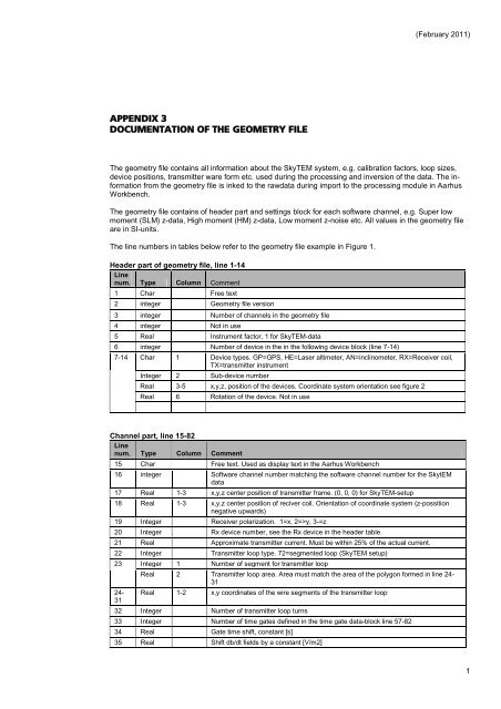
The line numbers in tables below refer to the geometry file example in Figure 1.<br />
Header part of geometry file, line 1-14<br />
Line<br />
num. Type Column Comment<br />
1 Char Free text<br />
2 integer Geometry file version<br />
3 integer Number of channels in the geometry file<br />
4 integer Not in use<br />
5 Real Instrument factor, 1 <strong>for</strong> SkyTEM-data<br />
6 integer Number of device in the in the following device block (line 7-14)<br />
7-14 Char 1 Device types. GP=GPS, HE=Laser altimeter, AN=inclinometer, RX=Receiver coil,<br />
TX=transmitter instrument<br />
Integer 2 Sub-device number<br />
Real 3-5 x,y,z, position of the devices. Coordinate system orientation see figure 2<br />
Real 6 Rotation of the device. Not in use<br />
Channel part, line 15-82<br />
Line<br />
num. Type Column Comment<br />
15 Char Free text. Used as display text in the Aarhus Workbench<br />
16 integer Software channel number matching the software channel number <strong>for</strong> the SkytEM<br />
data<br />
17 Real 1-3 x,y,z center position of transmitter frame. (0, 0, 0) <strong>for</strong> SkyTEM-setup<br />
18 Real 1-3 x,y,z center position of reciver coil. Orientation of coordinate system (z-possition<br />
negative upwards)<br />
19 Integer Receiver polarization. 1=x, 2=>y, 3-=z<br />
20 Integer Rx device number, see the Rx device in the header table.<br />
21 Real Approximate transmitter current. Must be within 25% of the actual current.<br />
22 Integer Transmitter loop type. 72=segmented loop (SkyTEM setup)<br />
23 Integer 1 Number of segment <strong>for</strong> transmitter loop<br />
24-<br />
31<br />
Real 2 Transmitter loop area. Area must match the area of the polygon <strong>for</strong>med in line 24-<br />
31<br />
Real 1-2 x,y coordinates of the wire segments of the transmitter loop<br />
32 Integer Number of transmitter loop turns<br />
33 Integer Number of time gates defined in the time gate data-block line 57-82<br />
34 Real Gate time shift, constant [s]<br />
35 Real Shift db/dt fields by a constant [V/m2]<br />
1