(February 2011) Example of SkyTEM Geometry file <strong>for</strong> Aarhus Workbench Line number 1 SkyTEM Geometry file <strong>for</strong> Aarhus Workbench 2 7 !FileVersion number {int} 3 3 !NChannel, number of channels. 4 3 !Not in use 5 1 !InstrumentFactor, 1 <strong>for</strong> SkyTEM 6 8 !NDevice, number of device 7 GP 1 15.32 0.98 -0.24 0 !DeviceName, DeviceNumber, X, Y, Z, Rot 8 GP 2 15.32 1.02 -0.24 0 9 HE 1 8.15 9.90 -0.10 0 10 HE 2 8.15 -9.90 -0.10 0 11 AN 1 -15.87 0.50 -0.36 0 12 AN 2 -15.87 -0.50 -0.36 0 13 RX 1 -16.06 0.00 -2.13 0 14 TX 1 16.48 -0.34 0.00 0 15 Ch. #1 - Super Low Moment - z component 16 1 !Channel Number 17 0.0 0.0 0.0 !TxPos, Relative position of Transmitter, negative in the air [m] {float} 18 -16.06 0.0 -2.13 !RxPos, Relative position of Receiver [m] {float} 19 3 !Receiver polarization (1->x, 2->y, 3->z) 20 1 !Rx device number {integer} 21 11 !Current interval (A) {float} 22 72 !LoopType, 72=Segmented loop 23 8 494.4 !if Loop=72: NumberOfWires, LoopArea [m2] {>=2 or 0,float} 24 -15.34 -2.03 !if Loop=72: 1st wire begin <strong>and</strong> end points (x0,y0) -> (x1,y1)) 25 -7.13 -10.26 26 7.13 -10.26 27 15.34 -2.03 28 15.34 2.03 29 7.13 10.26 30 -7.13 10.26 31 -15.34 2.03 !if Loop=72: 8th wire begin point. Connects back to 1st wire begin point(x,y) 32 1 !NTurns, Number of turns in loop 33 26 !NGates, Number of gates 34 -0.7e-06 !Shift times by a constant [s] 35 0.0 !Shift fields by a constant [V/m2] 36 0.92 ! Shift fields by factor 37 5 0 !Default remove gates 1..X <strong>and</strong> Y..NGate, 0=no gates are removed 38 0 0 !Not in use. Default remove ... <strong>for</strong> noise datasets,0=no gates are removed 39 0 !Not in use. Median filter, number of data to remove from Low end {>=0, int} 40 0 !Not in use. Median filter, number of data to remove from High end {>=0, int} 41 1 1 -1 !SlopFilters be<strong>for</strong>e front gate, -1=no filter (3 numbers) 42 450E+3 300E+03 1 !Filter cut off frequency [Hz] (3 numbers) 43 0 0.5e-6 0.01 !Use Frontgate (1=yes, 0=no),FrontGate time[s], Primary field damping factor 44 1 !Lowpass filter after front gate, -1 or UseFrontGate=0 means no filter 45 300.0E+3 !FrontGateFilter cut off frequency [Hz] (1 numbers) 46 250.0 1 !Repetition frequency [Hz] <strong>and</strong> RepFreqID [1..NChannel] 47 1 !Wave<strong>for</strong>mType, 1 <strong>for</strong> exponential, 2 <strong>for</strong> picewise linear 48 31000 !if Wave<strong>for</strong>mType=1, TOn: Exp. decay constant (time constant) 49 65.0 !if Wave<strong>for</strong>mType=1, TOn: 1st ramp [%] {>=0 =0 0, float} 54 25.0 !if Wave<strong>for</strong>mType=1, TOn: 2nd ramp [%] {>=0 =0 0, float} 57 1.195E-06 0.39E-06 1.61E-06 1.0 0.0![Gatecenter, Start, Width, GateFactor, GateSTD] 58 3.195E-06 2.39E-06 1.61E-06 1.0 0.0 59 5.195E-06 4.39E-06 1.61E-06 1.0 0.0 60 7.195E-06 6.39E-06 1.61E-06 1.0 0.0 61 9.195E-06 8.39E-06 1.61E-06 1.0 0.0 62 11.195E-06 10.39E-06 1.61E-06 1.0 0.0 63 13.195E-06 12.39E-06 1.61E-06 1.0 0.0 64 15.195E-06 14.39E-06 1.61E-06 1.0 0.0 65 17.195E-06 16.39E-06 1.61E-06 1.0 0.0 66 20.195E-06 18.39E-06 3.61E-06 1.0 0.0 67 24.695E-06 22.39E-06 4.61E-06 1.0 0.0 68 30.695E-06 27.39E-06 6.61E-06 1.0 0.0 69 38.195E-06 34.39E-06 7.61E-06 1.0 0.0 70 47.195E-06 42.39E-06 9.61E-06 1.0 0.0 71 58.695E-06 52.39E-06 12.61E-06 1.0 0.0 72 73.195E-06 65.39E-06 15.61E-06 1.0 0.0 73 91.695E-06 81.39E-06 20.61E-06 1.0 0.0 74 115.195E-06 102.39E-06 25.61E-06 1.0 0.0 75 144.195E-06 128.39E-06 31.61E-06 1.0 0.0 76 181.195E-06 160.39E-06 41.61E-06 1.0 0.0 77 227.695E-06 202.39E-06 50.61E-06 1.0 0.0 78 285.695E-06 253.39E-06 64.61E-06 1.0 0.0 79 359.195E-06 318.39E-06 81.61E-06 1.0 0.0 80 451.695E-06 400.39E-06 102.61E-06 1.0 0.0 81 568.195E-06 503.39E-06 129.61E-06 1.0 0.0 82 714.695E-06 633.39E-06 162.61E-06 1.0 0.0 83 Ch. #2 - High Moment - z component 84 .. 85 .. 86 .. 87 Ch. #6 – High Moment Noise - z component 88 .. 89 .. 90 SkyTEM Geometry file <strong>for</strong> Aarhus Workbench Figure 1. Geometry file example 3
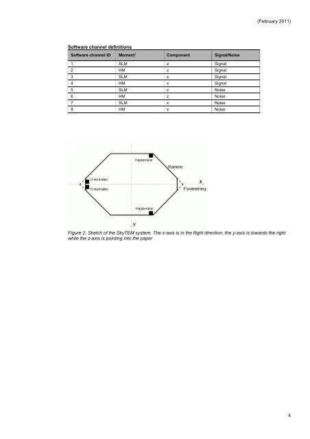
(February 2011) Software channel definitions Software channel ID Moment 1 Component Signal/Noise 1 SLM z Signal 2 HM z Signal 3 SLM x Signal 4 HM x Signal 5 SLM z Noise 6 HM z Noise 7 SLM x Noise 8 HM x Noise Figure 2. Sketch of the SkyTEM system. The x-axis is in the flight direction, the y-axis is towards the right while the z-axis is pointing into the paper 4