guideline and standards for skytem measurements, processing and ...
guideline and standards for skytem measurements, processing and ...
guideline and standards for skytem measurements, processing and ...

Create successful ePaper yourself
Turn your PDF publications into a flip-book with our unique Google optimized e-Paper software.
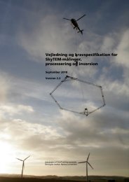
3 SKYTEM CONFIGURATION AND MEASUREMENT<br />
STRATEGIES<br />
Below we present the various SkyTEM configurations, positioning of flight lines<br />
<strong>and</strong> determination of flight speed <strong>and</strong> altitude. The SkyTEM method is also<br />
described in ref. /8/.<br />
3.1 SkyTEM configurations<br />
Generally, the SkyTEM system measurement configuration needs to be<br />
adjusted to fit the mapping area <strong>and</strong> purpose. The system may be adjusted in a<br />
number of ways to facilitate mapping of very surface-near geological structures,<br />
profound structures or intermediary layers. Appendix 1 comprises a number of<br />
st<strong>and</strong>ard configurations, optimized <strong>for</strong> each of the mentioned mapping<br />
purposes.<br />
The system uses a combination of two moments, super low moment (SLM) <strong>and</strong><br />
high moment (HM). Previous versions of the SkyTEM also used low moment<br />
(LM). This is not currently the case, as LM was replaced by SLM. The SLM <strong>and</strong><br />
HM have the following characteristics:<br />
Super low moment (SLM)<br />
One turn is employed on the transmitter frame, <strong>and</strong> a current of approx. 10 A is<br />
used. The first usable gate time depends on the choice of HM <strong>and</strong> is<br />
somewhere in the 10-15 ìs interval. SLM yields maximum resolution of surfacenear<br />
geological structures.<br />
High moment (HM)<br />
The maximum transmitter current is 110 A in 1 to 4 turns. The first usable gate<br />
time occurs at approx. 30-70 ìs. Two frame sizes are available, measuring<br />
approx. 314 m 2 <strong>and</strong> 494 m 2 . When the smaller frame is used, configurations with<br />
1 (HM1), 2 (HM2) or 4 (HM4) turns are possible. If the larger frame is employed,<br />
four turns are always used.<br />
The larger frame is mainly used <strong>for</strong> mappings requiring a substantial mapping<br />
depth (up to 300 m), while the smaller frame is used where mapping depths of<br />
up to 200 m are needed. If HM1 <strong>and</strong> HM2 are used, the mapping depth is more<br />
limited (100-150 m) as <strong>measurements</strong> are limited to 1.2-4 ms (versus the normal<br />
10 ms) period.<br />
In two or four turn configurations, SLM will not yield as early gate times as when<br />
using one turn with a single turn.<br />
Moment combinations <strong>and</strong> lateral resolution<br />
SLM in combination with HM1 <strong>and</strong> HM2 yield a very dense lateral data sampling<br />
resulting in a very high resolution of surface-near geology. By combining SLM<br />
<strong>and</strong> HM4, considerable mapping depth is achieved, but as transmission occurs<br />
at a lower frequency <strong>and</strong> over a longer period of time, lateral data sampling is<br />
less dense <strong>and</strong> the geology of very surface-near there<strong>for</strong>e somewhat limited.<br />
For approx. every 20 th shift of moment, the HM background noise is measured<br />
at a reduced stack size. This measurement is used during <strong>processing</strong> to assess<br />
the noise.<br />
6