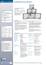
Installation and Operating Instructions GEN-AUTO Energy Division
Installation and Operating Instructions GEN-AUTO Energy Division
Installation and Operating Instructions GEN-AUTO Energy Division

Create successful ePaper yourself
Turn your PDF publications into a flip-book with our unique Google optimized e-Paper software.
Section 5 Operation<br />
5 6 7<br />
5.1 Controls <strong>and</strong> Indicators<br />
1<br />
3<br />
4<br />
9<br />
2<br />
8<br />
13<br />
10<br />
15<br />
14<br />
12 11 16 17<br />
1. Four-digit, seven-segment LED display. This displays the selected parameter from the list<br />
alongside. Use the button to select which parameter is to be displayed, as indicated by the<br />
adjacent LEDs. The button selects the parameters in sequence, as follows. Note<br />
that line voltage readings are prefixed by ‘L’ while phase-neutral readings are<br />
prefixed by ‘n’.<br />
● Alternator voltage L1-L2, prefix L<br />
● Alternator voltage L1-N, prefix n<br />
● Alternator voltage L2-L3, prefix L<br />
● Alternator voltage L2-N, prefix n<br />
● Alternator voltage L3-L1, prefix L<br />
● Alternator voltage L3-N, prefix n<br />
27