

KM-650MAH-E Service manual - Hoshizaki
KM-650MAH-E Service manual - Hoshizaki
KM-650MAH-E Service manual - Hoshizaki

You also want an ePaper? Increase the reach of your titles
YUMPU automatically turns print PDFs into web optimized ePapers that Google loves.
5) Freeze Cycle – LED 1 is on. Comp remains energized, PM, FM, and LLV<br />
(<strong>KM</strong>‐515MAH-E) energize. WV and HGV de‐energize. For the first 5 minutes, CB will not<br />
terminate the freeze cycle. At the end of 5 minutes, F/S assumes control of the freeze<br />
cycle. As ice builds on the evaporator, the water level in the water tank lowers. Freeze<br />
continues until F/S opens, provided the 5-minute minimum freeze timer has terminated.<br />
Diagnosis: During the first 5 minutes of freeze, confirm that the evaporator temperature<br />
drops. If the evaporator is not cold, check to see if HGV is still open or if TXV is not<br />
opening properly, if WV is continuing to fill the reservoir, if there are improper icemaker<br />
pressures, or an inoperative Comp. After 5 minutes in freeze, disconnect black F/S<br />
connector from CB BLACK K5 connector. The icemaker should switch out of the freeze<br />
cycle ("G" CB - 15 second delay after F/S opens before terminating the freeze cycle). If<br />
the icemaker switches out of freeze with F/S removed, but would previously not switch<br />
out of freeze with F/S connected (long freeze - 3 beep alarm), F/S may be sticking.<br />
To check and clean F/S, see "IV.D. Float Switch Check and Cleaning." If the icemaker<br />
remains in freeze (longer than 15 seconds on "G" CB) after disconnecting the black F/S<br />
connector, replace CB.<br />
Note: Normal freeze cycle will last 20 to 40 minutes depending on model and<br />
conditions. Cycle times and pressures should follow performance data provided in<br />
this <strong>manual</strong>. See "III.C. Performance Data."<br />
6) Pump-Out Cycle – (10/20 second pump-out) – LEDs 1, 3, and 2 are on. LED 4 is<br />
on when S4 dip switch 3 & 4 are set to 3 off and 4 on (<strong>KM</strong>-320MAH-E). Comp<br />
remains energized, HGV energizes. WV energizes if S4 dip switch 3 off and 4 on.<br />
LLV (<strong>KM</strong>‐515MAH-E) and FM de‐energize. PM stops for 2 seconds, then reverses for<br />
10/20 seconds depending on pump‐out timer S4 dip switch 3 & 4 setting. When the<br />
pump-out timer expires, the pump-out is complete. The pump-out frequency control is<br />
factory set for every 10th cycle on <strong>KM</strong>-320MAH-E and every cycle for <strong>KM</strong>-515MAH-E<br />
and <strong>KM</strong>-<strong>650MAH</strong>-E. Generally no adjustment is required. However, the pump‐out<br />
frequency can be adjusted. The pump-out frequency control (S4 dip switch 5 & 6) can<br />
be set to have a pump-out occur every cycle, or every 2, 5, or 10 cycles. For details, see<br />
"II.C.3.d) Pump‐Out Frequency Control (S4 dip switch 5 & 6)."<br />
Timing of the first pump-out is dependent on CB. "E" CB first pump‐out is after the first<br />
freeze cycle. "G" CB first pump-out is determined by S4 dip switch 5 & 6. See the table<br />
below.<br />
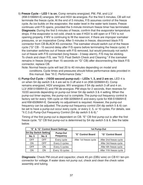
"E" & "G" Control Board Settings<br />
1st Pump-Out<br />
S4 Dip Switch Setting Pump-Out<br />
No. 5 No. 6 Frequency<br />
"E" Control Board "G" Control Board<br />
OFF OFF Every cycle After 1st freeze cycle After 2nd freeze cycle<br />
ON OFF Every 2 cycles After 3rd freeze cycle<br />
OFF ON Every 5 cycles After 6th freeze cycle<br />
ON ON Every 10 cycles After 11th freeze cycle<br />
Diagnosis: Check PM circuit and capacitor, check #5 pin (DBU wire) on CB K1 ten‐pin<br />
connector for voltage. If water does not pump out, check and clean the check valve<br />
assembly and tubing.<br />
37


