

KM-650MAH-E Service manual - Hoshizaki
KM-650MAH-E Service manual - Hoshizaki
KM-650MAH-E Service manual - Hoshizaki

You also want an ePaper? Increase the reach of your titles
YUMPU automatically turns print PDFs into web optimized ePapers that Google loves.
B. Control Board Check<br />
Before replacing CB that does not show a visible defect and that you suspect is bad,<br />
always conduct the following check procedure. This procedure will help you verify your<br />
diagnosis.<br />
Alarm Reset: If CB is in alarm (beeping), press the "ALARM RESET" button on CB<br />
while CB is beeping. WARNING! Risk of electric shock. Care should be<br />
taken not to touch live terminals. Once reset, the icemaker starts at the<br />
1-minute fill cycle. For audible alarm information, see "II.C.2. LED Lights<br />
and Audible Alarm Safeties."<br />
1) Check the dip switch settings to assure that S4 dip switch 3, 4, 7, 8, 9, 10 and S5 dip<br />
switch 1 through 5 ("G" CB) are in the factory default position. S4 dip switch 1, 2, 5, 6<br />
are cleaning adjustments and the settings are flexible. For factory default settings, see<br />
"II.C.3.a) Default Dip Switch Settings."<br />
2) Move the control switch to the "ICE" position. If the red "POWER OK" LED is on, control<br />
voltage is good, continue to step 3. If the "POWER OK" LED is off, check CT secondary<br />
circuit. CT output is 10.5VAC at 115VAC primary input. If the secondary circuit has<br />
proper voltage and the red LED is off, replace CB.<br />
If the secondary circuit does not have proper voltage, check CT primary circuit. Check<br />
for 115VAC at CB K1 connector pin #10 (BR wire) to a neutral (W wire) for 115VAC.<br />
(Always choose a neutral (W wire) to establish a good neutral connection when<br />
checking voltages.) For additional checks, see "IV.F.1. No Ice Production."<br />
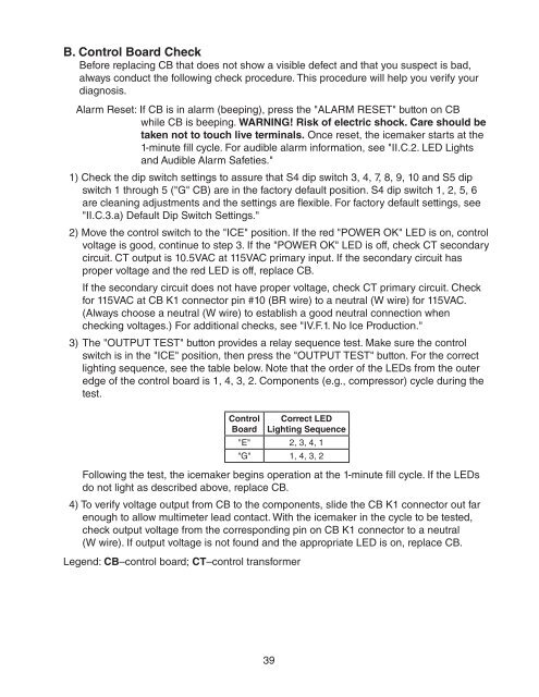
3) The "OUTPUT TEST" button provides a relay sequence test. Make sure the control<br />
switch is in the "ICE" position, then press the "OUTPUT TEST" button. For the correct<br />
lighting sequence, see the table below. Note that the order of the LEDs from the outer<br />
edge of the control board is 1, 4, 3, 2. Components (e.g., compressor) cycle during the<br />
test.<br />
Control<br />
Board<br />
Correct LED<br />
Lighting Sequence<br />
"E" 2, 3, 4, 1<br />
"G" 1, 4, 3, 2<br />
Following the test, the icemaker begins operation at the 1-minute fill cycle. If the LEDs<br />
do not light as described above, replace CB.<br />
4) To verify voltage output from CB to the components, slide the CB K1 connector out far<br />
enough to allow multimeter lead contact. With the icemaker in the cycle to be tested,<br />
check output voltage from the corresponding pin on CB K1 connector to a neutral<br />
(W wire). If output voltage is not found and the appropriate LED is on, replace CB.<br />
Legend: CB–control board; CT–control transformer<br />
39


