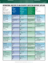
industry news - Chip Scale Review
industry news - Chip Scale Review
industry news - Chip Scale Review

You also want an ePaper? Increase the reach of your titles
YUMPU automatically turns print PDFs into web optimized ePapers that Google loves.
<strong>Chip</strong><strong>Scale</strong>®<br />
www.<strong>Chip</strong><strong>Scale</strong><strong>Review</strong>.com<br />
r e v i e w<br />
March 2007<br />
• Flip-<strong>Chip</strong> and Die-Attach Trends<br />
• Wire Bonders
One Stop Wafer Bumping & WLCSP with UAT<br />
Wafer Level <strong>Chip</strong>scale Package<br />
Wafer Bumping Services<br />
Gold Bumps<br />
Bump Height typically ranges from 2 to 25 microns and bump pitch may go as<br />
low as 35 micons<br />
Copper Pillar Bumps<br />
Copper pillar bumps with solder cap of either SnAg or pure Sn for fine pitch<br />
application. Bump pitch may go as low as 100 microns. Typical bump height is<br />
65 microns of copper pillar with 20 microns of solder cap.<br />
Small Solder Bumps<br />
Electroplated solder bumps either of SnAg or pure Sn fr fine pitch application.<br />
Bump height typically ranges between 25 to 100 microns. Bump pitch may go<br />
as low as 100 microns for lower bump heights.<br />
Large Solder Bumps<br />
Ball drop and ‘reflow’ bump height ranges between 150 to 350 microns<br />
depending on diameter or Under-bump metallization and solder ball size being<br />
used. Typical solder bump composition is SnAgCu (3.0% Ag and 0.5% Cu)<br />
Repassivation & pad redistribution<br />
Polymide or Bensocyclobutene as the repassivation layer for enhancing the<br />
performance and reliability of wafer-level packaging redistribution of bond pads<br />
into matric arrays to cater for devices not currently designed for wafer bumping.<br />
• Backgrind<br />
• Laser Mask<br />
• Test<br />
• Singulation<br />
• Inspection<br />
• Tape & Reel<br />
• Qualification Reports<br />
available at this time<br />
Unisem-Advanpack Technologies Sdn Bhd (*UAT*), a joint venture between Unisem (M) Berhad (“Unsiem”) and Advanpack<br />
Solutions Pte Ltd., located in Ipoh, Malaysia, is one of the first independent wafer bumping service providers in Malaysia.<br />
At UAT we offer a one-stop center for wafer bumping services which includes gold bumps, electroplated solder bumps<br />
through “ball drop” process. We also offer pad redistribution and repassivation for wafer sizes of 4, 6 and 8-inch diameter.<br />
Unisem Europe Ltd.<br />
Bernard Ramsay<br />
European Sales Director<br />
Parkway, Pen-y-fan Industrial Estate<br />
Crumlin<br />
South Wales NP11 3XT<br />
Bernie.Ramsay@Unisem-eu.com<br />
Cell/Mobile +44 (0)7779 657696<br />
Unisem USA<br />
Mike Stokman<br />
North American VP of Sales<br />
Unisem USA<br />
1893 Klondike Road<br />
Livermore<br />
CA 94550<br />
Mike.stokman@unisem-us.com<br />
Cell/Mobile + 925 980 6515
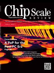
CONTENTS<br />
The International Magazine of <strong>Chip</strong>-<strong>Scale</strong><br />
Electronics, Flip-<strong>Chip</strong> Technology, Optoelectronics<br />
Interconnection and Wafer-Level Packaging<br />
March 2007<br />
Volume 11, Number 2<br />
THE COVER<br />
Someone (was it old Will Shakespeare, again?)<br />
once said, “There’s nothing new under the sun.”<br />
We beg to differ! There’s lots new, especially in the<br />
machines that are used to package the chips we all<br />
love (and either directly or indirectly profit from).<br />
Over the past few years, we’ve seen a consolidation<br />
in the sub-industries that make wire bonders and die<br />
attach. It’s been less than two years since pioneer<br />
Kulicke & Soffa Industries sold its wedge bonding<br />
product line to Orthodyne, probably a smart move<br />
for both. And almost while we weren’t looking, The<br />
former ESEC, after becoming a Unaxis brand,<br />
became an Oerliken brand!<br />
Editor Ron Iscoff looks at the good and bad of today’s<br />
wire bonders, and Orthodyne chips in with a new<br />
ribbon bonding process. Meanwhile, Terry Thompson,<br />
our senior editor from the cold climes of the Midwest,<br />
shook off the snow long enough to report on<br />
machines for die attach and flip-chip packaging.<br />
(Illustration for <strong>Chip</strong> <strong>Scale</strong> <strong>Review</strong> by<br />
Design 2 Market) [design2marketinc.com]<br />
COVER FEATURES<br />
Are Wire Bonders Running Out of Steam? 28<br />
How this Essential IC Assembly Tool Is Keeping Pace<br />
Ron Iscoff, Editor<br />
Wire bonders are becoming smarter, faster and more cost-effective on<br />
the assembly line. In the bonder’s 50+ year history, the machines have<br />
become not only the icon for IC assembly, but the most-needed tool at<br />
every IC assembler. Is there room for improvement? Of course, and<br />
we’ll explore that topic in this article.<br />
International Directory of Production Wire Bonders<br />
<strong>Chip</strong> <strong>Scale</strong> <strong>Review</strong> Staff<br />
34<br />
Flip-<strong>Chip</strong> Processing Secrets:<br />
36<br />
Saving Money and Saving Time<br />
Terrence E. Thompson, Senior Editor<br />
The biggest “secret” to successful, automated flip-chip production is<br />
the careful selection of the increasingly intelligent equipment that makes<br />
the technology more affordable, reliable and amazingly accurate. Your<br />
choice of the best tools for your applications is going to result in your<br />
company either saving lots of money, or—alternatively—writing a<br />
check for a dust-gathering behemoth that spends much of its time<br />
sitting in a corner like a wallflower at the prom.<br />
International Directory of Flip <strong>Chip</strong> & Die Attach Bonders/Aligners<br />
<strong>Chip</strong> <strong>Scale</strong> <strong>Review</strong> Staff<br />
43<br />
The Challenge of Packaging Small Power Devices 45<br />
Dr. Christoph Luechinger and Siegbert Haumann,<br />
Orthodyne Electronics Corp.<br />
Until recently, fine wire ball bonding and Cu strap attachment were the<br />
main interconnect techniques for power semiconductors smaller than the<br />
TO-252. A new, large aluminum ribbon bonding process, however, has<br />
overcome past size restrictions, enabling the use of this technology to<br />
overcome weaknesses in traditional approaches.<br />
CONTINUED >><br />
<strong>Chip</strong> <strong>Scale</strong> <strong>Review</strong>, at 7291 Coronado Dr., Suite 8, San Jose, CA 95129<br />
(ISSN 1526-1344), is published eight times a year, with issues in<br />
January-February, March, April, May-June, July, August-September,<br />
October and November-December.<br />
Periodical postage paid at San Jose, Calif., and additional offices.<br />
POSTMASTER: Send address changes to <strong>Chip</strong> <strong>Scale</strong> <strong>Review</strong> magazine,<br />
7291 Coronado Dr., Suite 8, San Jose, CA 95129.<br />
<strong>Chip</strong> <strong>Scale</strong> <strong>Review</strong> ■ March 2007 ■ [<strong>Chip</strong><strong>Scale</strong><strong>Review</strong>.com] 1
CONTENTS<br />
FEATURE ARTICLE<br />
High-Speed Stencil Cleaning Techniques for IC 53<br />
Substrate-Level Assembly Lower Total Costs<br />
Trevor Warren, DEK<br />
Printing-type processes have quickly earned acceptance<br />
in semiconductor and other sophisticated packaging<br />
applications. Stencil printing is an enabling technology<br />
for many wafer-bumping and similar uses. Integrating<br />
proven, innovative stencil cleaning process improvements<br />
into operations, for example, is a very efficient<br />
way for companies to control costs and improve yields.<br />
LATE NEWS<br />
STATS <strong>Chip</strong>PAC Joins Billion-Dollar-Buyout Club<br />
Singapore—Less than four months after the Carlyle Group bid $5.4 billion<br />
for Advanced Semiconductor Engineering, Taiwan, a Singapore group has<br />
offered to buy out STATS <strong>Chip</strong>PAC’s available unowned shares for cash.<br />
In late February, Temasek Holdings Pte., Singapore’s state-owned investment<br />
company, offered up to $1.6 billion for all remaining shares of the Singaporebased<br />
IC assembly and test provider. Temasek’s wholly-owed subsidiary<br />
Singapore Technologies Semiconductors Pte. currently owns 35.6 percent of<br />
STATS <strong>Chip</strong>PAC. [statschippac.com]<br />
DEPARTMENTS<br />
Publisher’s Letter Gene Selven<br />
We’re counting our ABCs for you!<br />
Assembly Lines Ron Iscoff<br />
Farewell to two remarkable leaders<br />
Standards Mark Bird<br />
Package-on-Package is ready to take-off<br />
Test Patterns Paul M. Sakamoto<br />
The ‘mainframe mentality’ lives on!<br />
Industry News<br />
Calendar<br />
WLCSP Forum Manuel H. Mere<br />
Ongoing migration to finer WLCSP pitches<br />
Inside Patents A. Jason Mirabito and Carol Peters<br />
Underfill: patent offers a new approach to an old problem<br />
Index to 2006 Articles<br />
What’s New!<br />
Back of the Book Dr. David Tuckerman<br />
5 critical challenges for 3D packaging<br />
Ad Index/More News/Sales Offices<br />
5<br />
7<br />
8<br />
10<br />
13<br />
21<br />
52<br />
57<br />
58<br />
60<br />
62<br />
64<br />
<strong>Chip</strong> <strong>Scale</strong> <strong>Review</strong> ■ March 2007 ■ [<strong>Chip</strong><strong>Scale</strong><strong>Review</strong>.com] 3
Technologies, Inc.<br />
Your Global Provider of Leading Edge<br />
Semiconductor Packages<br />
NTK Technologies<br />
offers a wide range<br />
of cutting-edge<br />
ceramic and organic<br />
packages for<br />
ASIC<br />
MPU<br />
Sensors<br />
MEMS<br />
• computer<br />
• consumer<br />
• telecom<br />
• medical<br />
• automotive<br />
• and hi rel<br />
products<br />
Multi-Layer<br />
High Frequency<br />
OPTO<br />
RF<br />
High Reliability<br />
High Density<br />
Visit us at OFC<br />
Booth #1003 March 27-29<br />
Anaheim Convention Center<br />
Phoenix, Irvine, San Jose, Chicago, Boston, Austin, Dallas,<br />
Arizona California California Illinois Massachusetts Texas Texas<br />
602/470-9898 949/580-0607 408/727-5180 847/788-9795 508/820-0220 512/340-0194 972-235-1625<br />
Visit our web-site at www.ntktech.com
VOLUME 11, NUMBER 2<br />
The International Magazine of <strong>Chip</strong>-<strong>Scale</strong><br />
Electronics, Flip-<strong>Chip</strong> Technology, Optoelectronic<br />
Interconnection and Wafer-Level Packaging<br />
STAFF<br />
Gene Selven Publisher<br />
7291 Coronado Dr., Ste. 8, San Jose, CA 95129<br />
b 408.996.7016 > 408.996.7871<br />
gselven@aol.com<br />
Ron Iscoff Editor & Associate Publisher<br />
929 Ebbetts Ave., Manteca, CA 95337<br />
b 209.824.1289 > 209.644.7747<br />
chipscale@gmail.com<br />
Terrence Thompson Senior Editor<br />
2303 Randall Rd. #140, Carpentersville, IL 60110<br />
b 847.515.1255<br />
tethompson@aol.com<br />
Steve Berry Contributing Editor<br />
b 408.369.7000 > 408.369.8021<br />
saberry@electronictrendpubs.com<br />
Dr. Tom Di Stefano Contributing Editor<br />
b 408.399.4501 > 408.395.0448<br />
tom@centipedesystems.com<br />
Dr. Subash Khadpe Contributing Editor<br />
skhadpe@semitech.com<br />
Harvey S. Miller Contributing Editor-at-Large<br />
b 650.328.4550 > 650.327.2360<br />
h.miller@ieee.org<br />
Paul M. Sakamoto Contributing Editor–Test<br />
b 925.924.9110 x148<br />
paul.sakamoto@inovys.com<br />
Sandra Winkler Contributing Editor<br />
b 408.369.7000 > 408.369.8021<br />
slwinkler@electronictrendpubs.com<br />
The Official Publication of the WLCSP Forum<br />
SUBSCRIPTION INQUIRIES<br />
Judy Levin <strong>Chip</strong> <strong>Scale</strong> <strong>Review</strong><br />
7291 Coronado Dr., Ste. 8, San Jose, CA 95129<br />
b 408.996.7016 > 408.996.7871<br />
csrsubs@chipscalereview.com<br />
ADVERTISING PRODUCTION<br />
INQUIRIES<br />
Kim Newman<br />
7291 Coronado Dr., Ste. 8, San Jose, CA 95129<br />
b 408.996.7016 > 408.996.7871<br />
csradv@aol.com<br />
REPRINTS<br />
Kim Newman b 408.996.7016<br />
8 csradv@aol.com<br />
ADVISORS<br />
Mark DiOrio MTBSolutions<br />
Dr. Tom Di Stefano Centipede Systems<br />
Charles R. Harper Technology Seminars Inc.<br />
Mark Murdza Antares Advanced Test Technologies<br />
Dr. Guna Selvaduray San Jose State University<br />
Dr. Thorsten Teutsch Pac Tech<br />
Dr. Dietrich Tönnies SUSS MicroTec AG<br />
Dr. David Tuckerman Tessera Technologies<br />
Professor C.P. Wong Georgia Tech<br />
Copyright © 2007 by Gene Selven & Associates Inc.<br />
<strong>Chip</strong> <strong>Scale</strong> <strong>Review</strong> (ISSN 1526-1344) is a registered trademark<br />
of Gene Selven & Associates Inc. Publishing headquarters are<br />
located at 7291 Coronado Drive, Suite 8, San Jose, CA 95129.<br />
All rights reserved.<br />
<strong>Chip</strong> <strong>Scale</strong> <strong>Review</strong> is published eight times a year.<br />
Subscriptions in the U.S. are available without charge to<br />
qualified individuals in the electronics <strong>industry</strong>. Subscriptions<br />
outside the U.S. (eight issues) by airmail are $60 per year to<br />
Canada or $60 to other countries. In the U.S., subscriptions<br />
by first class mail are $40 per year.<br />
PUBLISHER’S LETTER<br />
We’re Counting Our ABCs for You!<br />
By Gene Selven, Publisher [gselven@aol.com]<br />
As part of our continuing commitment to our advertisers and to our readers,<br />
we recently signed an agreement with the Audit Bureau of Circulations to<br />
audit the distribution of <strong>Chip</strong> <strong>Scale</strong> <strong>Review</strong>.<br />
Our advertisers and their agencies use ABC reports and analyses as the basis for<br />
media buying decisions. Publishers use ABC-audited data to manage circulation and<br />
develop marketing strategies.<br />
We have been audited by another auditing agency for the past five years, and we did<br />
not make this change lightly. We believe, however, that ABC will provide our advertisers<br />
with a more complete and more accurate picture of our readers and subscribers.<br />
This is important to our advertisers, of course, because their sponsorship enables us<br />
to produce and mail the publication to our domestic readership gratis.<br />
We are, unlike our chief competitor, a completely independent publisher. Our business<br />
consists solely of <strong>Chip</strong> <strong>Scale</strong> <strong>Review</strong> in English and Chinese; a web <strong>news</strong>letter and our<br />
International Wafer-Level Packaging Conference, which is jointly presented with the SMTA.<br />
We are also the leading publication in terms of both advertising revenue and editorial<br />
pages. We have worked hard to achieve this position—one which we’ve held for the last<br />
four years—and we aim to stay on top!<br />
Everyone will have total access to our semi-annual circulation audits. They will be<br />
posted on our web site at www.chipscalereview.com, and we invite you to visit anytime<br />
to see for yourself. Our first ABC audit will be available in June.<br />
By the way, I want to assure you that we will continue to guard your privacy. When<br />
the audit information is gathered, individual subscriber names are never released nor<br />
sold to any company without an individual’s prior explicit permission.<br />
China Bound<br />
As the March issue goes to press, I am preparing for my fourth annual trip to SEMICON<br />
China in Shanghai.<br />
To serve the booming China market, we publish two issues in Chinese each year. The<br />
first is for SEMICON China in March; the second is distributed at NEPCON South China,<br />
Shenzhen, in August. This year we will distribute nearly 10,000 copies in Shanghai.<br />
Over the past four-plus years, I’ve witnessed China’s amazing growth personally and<br />
have spoken to many of the individuals and companies responsible for it.<br />
We’re now in the early stages of preparing our NEPCON South China issue for distribution<br />
in Shenzhen.<br />
Please contact me or one of our representatives about placing your ad in this issue.<br />
If you’re planning to sell in China, you must make your name, company and products<br />
known—preferably in the Mainland’s own language. i<br />
<strong>Chip</strong> <strong>Scale</strong> <strong>Review</strong> ■ March 2007 ■ [<strong>Chip</strong><strong>Scale</strong><strong>Review</strong>.com] 5
ASSEMBLY LINES<br />
Farewell to Two Remarkable Leaders<br />
By Ron Iscoff, Editor [chipscale@gmail.com]<br />
The man who pioneered the disk<br />
drive and went on to create an<br />
<strong>industry</strong> has died.<br />
The man who built the world’s largest<br />
supplier of semiconductor assembly and<br />
packaging equipment has retired.<br />
Alan F. “Al” Shugart, author, entrepreneur,<br />
engineer, salesman, aficionado of<br />
eye-catching Hawaiian shirts, and<br />
founder of disk-drive makers Shugart<br />
Associates and Seagate Technology, died<br />
in December at age 76 in Monterey, Calif.<br />
His death was the result of complications<br />
from heart surgery, according to<br />
the New York Times.<br />
Over the past three decades, I met<br />
with Al about a dozen times in my role<br />
as a trade journalist.<br />
The last time I saw him was more<br />
than a decade ago at a San Jose conference,<br />
DISKON, an event for disk drive<br />
<strong>industry</strong> people.<br />
He was the keynoter, and while I<br />
don’t recall the subject of his talk, it was<br />
controversial and spiced with his<br />
unique wit. He mentioned in his talk,<br />
that he didn’t care very much for<br />
lawyers. He also said that excluded his<br />
daughter, Teri, who is a lawyer.<br />
Al was a native of Chino, Calif., and he<br />
studied engineering at the University of<br />
the Redlands, where he earned a bachelor’s<br />
degree in engineering physics. The<br />
day after he graduated, he went to work<br />
for IBM as a field service engineer.<br />
In 1955, while at the IBM Research<br />
Labs in San Jose, he led the team that<br />
developed the first hard disk drive,<br />
RAMAC (Random Access Method<br />
of Accounting and Control).<br />
He was also a political curmudgeon,<br />
who often had little<br />
patience with the dirty deeds of<br />
most politicos. In 1996, he<br />
attempted to place his dog,<br />
Ernest, on the ballot for congressman.<br />
He recounts this episode in<br />
his book, Ernest Goes to<br />
Washington.<br />
He’s also the author of<br />
Fandango: The Story of Two Guys<br />
Who Wanted to own a Restaurant,<br />
(which Al did), and The Wit and<br />
Wisdom of Al Shugart.<br />
In 1998, he left Seagate, which<br />
he had formed into the world’s<br />
largest independent maker of disk<br />
drives, to found Al Shugart<br />
International, a resource center to<br />
help budding entrepreneurs transform<br />
“great ideas into great companies with<br />
lasting value,” according to his web site<br />
[alshugart.com].<br />
The Story of ASM<br />
I have kept the Wiley-Asia book,<br />
Soaring Like Eagles in a coveted spot in<br />
my bookcase for about a year, since I<br />
received a review copy. Now that spring<br />
cleaning is here, the book has surfaced<br />
again and begs for comment.<br />
The authors are Patrick Lam, founder of<br />
ASM Pacific Technology, and Dr. Edmund<br />
Lam, who is Patrick’s son and a professor<br />
of electrical and electronic engineering<br />
at the University of Hong Kong.<br />
Al Shugart, the king of Hawaiian shirts. (Courtesy Chris Shugart)<br />
Although I suspect its publication<br />
was subsidized by the elder Lam, it’s a<br />
book worthy of discussion. As the book<br />
points out, ASM has maintained profitable<br />
growth for more than 30 years.<br />
Not everyone can say that!<br />
The book is subtitled, “ASM’s High-<br />
Tech Journey in Asia,” and within its<br />
modestly sized 250 pages, the Lams<br />
detail their journey from 1975—the<br />
founding—through 2005, when the<br />
book was printed.<br />
If you’re aligned with the equipment<br />
<strong>industry</strong>—semiconductor or otherwise—<br />
it’s likely you will learn a thing or two<br />
in this slender tome’s pages.<br />
Continued on page 63 >><br />
<strong>Chip</strong> <strong>Scale</strong> <strong>Review</strong> ■ March 2007 ■ [<strong>Chip</strong><strong>Scale</strong><strong>Review</strong>.com] 7
STANDARDS<br />
Package-on-Package Is Ready to Take-off<br />
By Mark Bird, Contributing Editor<br />
The Package-on-Package (PoP)<br />
family is one of the fastest<br />
growing formats in the market.<br />
In 2005, PoPs accounted for unit volumes<br />
of 100 million. Last year, that<br />
unit volume nearly doubled to 180+<br />
million and is expected to soar to<br />
around 700 million by 2010.<br />
The need for the PoP is to provide a<br />
cost-effective format for logic and<br />
memory stacking in the <strong>industry</strong> to<br />
address technical, business and logistic<br />
requirements.<br />
Dynamic Growth<br />
The <strong>industry</strong> has witnessed a range of<br />
new development programs and a mixture<br />
of non-standard solutions for PoPs<br />
over the past few years. The adoption of<br />
PoPs in 2004 greatly advanced mobile<br />
phone applications. In addition, the<br />
development of the JEDEC <strong>industry</strong><br />
standards have stimulated rapid PoP<br />
growth in volume, growth in applications<br />
and in the infrastructure. This<br />
dynamic growth has been experienced<br />
since early 2005.<br />
The PoP market is ready for take-off.<br />
JEDEC JC-63, the Stacked Package<br />
Product Committee has standardized<br />
the pinouts and functionality. The package<br />
registration outlines for the bottom<br />
and top packages have been addressed<br />
by the JC-11 Packaging Committee.<br />
A design-guide standard has also<br />
been created to address future configurations.<br />
This standardization coordination<br />
between the JEDEC committees<br />
allows the end-customer the flexibility<br />
to buy the lower, upper and stacked<br />
combination from a variety of different<br />
suppliers, giving the end-customer the<br />
ability to take advantage of high volumes<br />
at the lowest possible assembly and<br />
packaging costs.<br />
The three JC-11 outline registrations<br />
and design guide are:<br />
• Lower PoP Package; Very Thin Profile;<br />
Fine Pitch; Square;<br />
• Stackable Ball Grid 0.50mm Ball Pitch<br />
Array Family-MO-266<br />
• Upper PoP Package; Low Profile, Thin<br />
Profile and Very Thin Profile; Fine<br />
Pitch; Square; 0.65 and 0.50mm Ball<br />
Pitch Array Family-MO-273.<br />
Future Configurations<br />
The Lower and Upper PoP Design Guide<br />
was established to set the stage for<br />
future configurations. The Design<br />
Guide is 4.22, Issue A and was published<br />
in November 2005.<br />
PoP with single bottom die<br />
PoP with stacked bottom die<br />
The latest package registration<br />
revision is available at www.jedec.org<br />
in PDF format for downloading at<br />
no charge.<br />
All three PoP standards will undergo<br />
revisions to add 0.80mm ball pitch for<br />
the upper packages, as well as 0.40mm<br />
ball pitch for the lower package. This<br />
The <strong>industry</strong> has witnessed a range of new development programs and<br />
a mixture of non-standard solutions for PoPs over the past few years.<br />
would mean additional variations to the<br />
registration outlines, as well as an update<br />
to the Lower and Upper PoP Design<br />
Guide. The projected time of this activity<br />
will be late this year. i<br />
Mr. Bird is a Technology Fellow and the<br />
COO at Mbird and Associates Semiconductor<br />
Assembly, Packaging and Standardization<br />
Consultants in Apache Junction, Ariz. He<br />
is also the chairman of the JC-11 Packaging<br />
Standards Committee and technical<br />
advisor/chief delegate for the United States<br />
to the IEC TC47 and SC47D Semiconductor<br />
Committees. [j_mark_bird@yahoo.com]<br />
8<br />
<strong>Chip</strong> <strong>Scale</strong> <strong>Review</strong> ■ March 2007 ■ [<strong>Chip</strong><strong>Scale</strong><strong>Review</strong>.com]
plasma cleaning solutions<br />
With productivity 150% of conventional<br />
models and patented parallel plate<br />
technology that delivers superior<br />
results for both etching and<br />
surface modification, interest in<br />
Panasonic’s plasma solution<br />
continues to skyrocket.<br />
Experience <strong>industry</strong>-leading<br />
mold resin adhesion and under-fill<br />
wettability, reduced incidence<br />
peel-off, voids and cracks.<br />
Ideal for all manufacturers<br />
and for all volume levels.<br />
It’s brilliant.<br />
PSX303
TEST PATTERNS<br />
The ‘Mainframe Mentality’ Lives On!<br />
By Paul M. Sakamoto, Contributing Editor–Test [paul.sakamoto@inovys.com]<br />
I<br />
would guess that about half of<br />
you who read this column<br />
remember the time when mainframe<br />
computers roamed the land.<br />
The closely related mini-computer<br />
was its scaled-down little brother. Aside<br />
from the fact that they were very large<br />
by today’s standards, these machines all<br />
had proprietary operating systems and<br />
programming languages.<br />
This required specialized training for<br />
the various models from different manufacturers.<br />
Additionally, the networking<br />
between these machines was very difficult<br />
and aided the growth of specialized<br />
companies to address the task.<br />
Slow to Adopt Standards<br />
The biggest reason that the <strong>industry</strong> was<br />
slow to adopt standards was that it<br />
allowed vendors to keep their customers<br />
virtually enslaved once users adopted a<br />
maker’s proprietary system.<br />
It also allowed the manufacturer to<br />
charge for a very wide variety of related<br />
goods and services that only they could<br />
provide.<br />
Fortunately, today we have standards<br />
for software, applications and networking<br />
that are applied very broadly. These<br />
standards allow the direct re-use of data<br />
and information on virtually all current<br />
computers, smart phones, PDAs, and<br />
other computing machines.<br />
My rant today is that this is not the<br />
case for ATE.<br />
3600Plus & 3700Plus<br />
More performance with<br />
fewer limitations.<br />
The 3600Plus and 3700Plus wire bonders break new ground<br />
in innovation and design. Offering you more performance,<br />
options and versatility, the Plus Series combines intuitive<br />
technology with quality and reliability:<br />
• PowerRibbon TM Option for ribbon sizes 20 mil x 4 mil to<br />
80 mil x 8 mil<br />
• Bond Process Monitoring (BPM) flags suspect bonds in<br />
real-time, stores process information for later evaluation<br />
• Active Loop Control (ALC) bondheads allow best-in-class<br />
loop control and non-destructive pulltesting<br />
• Offline Programming Tool (OPT) converts CAD files into<br />
machine process programs, maximizing machine uptime<br />
New machine capabilities for greater performance, new<br />
international offices for better service, and a new interconnect technology<br />
— Orthodyne is committed to giving customers more.<br />
10<br />
<strong>Chip</strong> <strong>Scale</strong> <strong>Review</strong> ■ March 2007 ■ [<strong>Chip</strong><strong>Scale</strong><strong>Review</strong>.com]
Now, some of you may say, “Hey,<br />
Paul, you’re wrong. Company ABC<br />
adheres to the IEEE x standard.”<br />
This is likely true, but it is completely<br />
not the point. One could also say,<br />
“What about the Semiconductor Test<br />
Consortium/Open Architecture<br />
Initiative?” It’s a decent shot, but so<br />
far is more widely talked about than<br />
widely used. What I am talking about is<br />
the ability to develop a program on a<br />
tester from one company and run it on<br />
a standards-compliant tester from<br />
another company without any new<br />
programming.<br />
This just doesn’t happen today. The<br />
programming languages for each tester<br />
are different enough to require a conversion<br />
process for all program porting.<br />
This is a time-consuming and expensive<br />
process in most cases. It can also be<br />
error-prone, which is the most expensive<br />
problem of all.<br />
Mainframe Mentality<br />
The main reason that ATE companies<br />
promulgate the proprietary model—<br />
while sending delegates to standards<br />
meetings—is that they still have the old<br />
mainframe mentality.<br />
These manufacturers hope to protect<br />
their domains by making sure their customers<br />
are enslaved by their sunk cost<br />
in training, programs, infrastructure<br />
and other legacy ballast. The customers<br />
become enslaved by their own expertise<br />
with these systems.<br />
The cost of this model is high to all<br />
parties. The ATE companies miss the<br />
leverage of having the common issues<br />
be common. That is, they spend a lot of<br />
time working out the details of their<br />
Mainframe computers have come along way over<br />
the years. This is a photo of the original ENIAC<br />
computer that occupied a football-sized room.<br />
(U.S. Army photo)<br />
proprietary language and architecture<br />
instead of spending those resources on<br />
market differentiation and added value.<br />
Continued on page 63 >><br />
Patent Pending<br />
PowerRibbon <br />
More power with<br />
fewer connections.<br />
For years, Orthodyne’s ultrasonic small and large wire bonders have led the<br />
market in innovation and efficient, reliable performance. Our new<br />
PowerRibbon technology extends that tradition as it creates a new<br />
category of interconnect for power devices.<br />
Sized 20 x 4 mil to 80 x8mil,PowerRibbonoffers the solution to smaller<br />
packaging – more power with fewer connections. PowerRibbon combines<br />
the flexibility and robustness of large aluminum wire bonding<br />
with greater current-carrying capacity and lower RDS ON . Efficient, reliable<br />
and retrofittable, PowerRibbon is the most advanced interconnect<br />
alternative for small SO8, PQFN type leadframe applications as well<br />
as complex power modules.<br />
To find out more about PowerRibbon or the Plus Series<br />
bonders, contact us.<br />
16700 Red Hill Avenue<br />
Irvine, CA 92606-4802<br />
Phone: +1-949-660-0440<br />
sales@orthodyne.com<br />
www.orthodyne.com<br />
Orthodyne Electronics GmbH<br />
Lina-Ammon-Strasse 15<br />
90471 Nuernberg, Germany<br />
Ph: +49-(0)911-98813-0<br />
Fax: +49-(0)911-98813-20<br />
Laerchenster. 2<br />
83533 Edling, Germany<br />
Ph: +49-8071-93215<br />
Fax: +49-8071-93217<br />
<strong>Chip</strong> <strong>Scale</strong> <strong>Review</strong> ■ March 2007 ■ [<strong>Chip</strong><strong>Scale</strong><strong>Review</strong>.com] 11
More than meets the eye<br />
Compatibility-proven Material Sets from Henkel.<br />
Trust Henkel's Material Sets that truly work together.<br />
Trying to force non-optimized materials to work together in advanced packages and<br />
assemblies? At Henkel, our materials are specifically designed to work together, delivering<br />
tested, reliable and guaranteed compatible material sets for all of your semiconductor<br />
packaging and circuit board assembly requirements.<br />
Contact our application experts today for material set solutions that work:<br />
Henkel Americas: +1 949 789 2500 Henkel Europe: +44 1442 278 000 Henkel Asia: +852 2233 0000<br />
Across the Board. Across the Globe.<br />
Loctite, Hysol and Multicore are trademarks of Henkel Corporation, U.S.A. © Henkel Corporation, 2007. All rights reserved. 4178 01/2007<br />
www.electronics.henkel.com
INDUSTRY NEWS<br />
APEX 2007 Los Angeles: A Report from Smogville<br />
By Ron Iscoff, Editor<br />
The IPC’s APEX show,<br />
which trimmed the sails<br />
from the venerable<br />
and—until 2000—<br />
unchallenged NEPCON<br />
West behemoth seven<br />
years ago, has transformed<br />
itself into a<br />
regional printed circuit<br />
board show.<br />
This is not surprising,<br />
since it’s co-located with<br />
the same trade group’s<br />
Printed Circuits Expo.<br />
Regional Show<br />
Certainly, there is nothing wrong<br />
with a regional printed circuits<br />
show, but there’s also not much to<br />
Teraflop Computer Shrinks to Fingernail-Sized Processor<br />
Santa Clara, Calif.—Intel<br />
Corporation researchers<br />
have developed the world’s<br />
first programmable processor<br />
that delivers supercomputer-like<br />
performance from<br />
a single 80-core chip not<br />
much larger than the size of<br />
a fingernail. The processor<br />
uses less electricity than most<br />
of today’s home appliances—<br />
just 62 watts.<br />
The “Tera-scale computing”<br />
research is aimed at delivering<br />
teraflop—or trillions of calculations<br />
per second—performance.<br />
Technical details of the teraflop<br />
research chip were presented in<br />
February at the annual International<br />
Solid State Circuits Conference in<br />
San Francisco.<br />
The teraflop chip also features a<br />
mesh-like “network-on-a-chip”<br />
It’s 50 years for IPC and the fourth location for APEX this<br />
year. Visitors benefitted from generally excellent weather and<br />
a revitalized downtown Los Angeles. (<strong>Chip</strong> <strong>Scale</strong> <strong>Review</strong>)<br />
see for chip devotees, unless they’re<br />
also making printed circuit boards.<br />
And there’s no reason, really, to<br />
Continued on page 15 >><br />
This board houses Intel’s 80-core teraflops research<br />
chip. The board contains working silicon and is the<br />
world’s first programmable chip to achieve teraflops<br />
performance while consuming very little power. (Intel)<br />
architecture that enables super-high<br />
bandwidth communications<br />
between the cores, and is capable of<br />
moving terabits of data per second<br />
inside the chip.<br />
Intel has no plans to bring this<br />
exact chip designed with floating<br />
point cores to market.<br />
Continued on page 15 >><br />
IBM and Intel Claiming<br />
45nm Transistor Honors<br />
Intel President Paul Ottolini holds an Intel Core 2 Duo<br />
microprocessor. (Intel Corp.)<br />
San Jose—In announcements released<br />
nearly simultaneously, giants IBM and<br />
Intel are both claiming next-generation 45<br />
nanometer transistor honors employing<br />
separate processes with apparently similar<br />
materials.<br />
Intel, Santa Clara, calls its technology,<br />
“The biggest change to computer chips in<br />
40 years” and “one of the biggest advancements<br />
in fundamental transistor design.”<br />
IBM, Yorktown Height, N.Y., terms its work<br />
“The first fundamental change to the basic<br />
transistor in 40 years.” Neither company<br />
names the other in their <strong>news</strong> releases.<br />
Continued on page 19 >><br />
A New Interconnection Technology<br />
Blooms at Jerry Falwell’s University<br />
Los Angeles—What do the Rev. Jerry<br />
Falwell and Liberty University, the fundamentalist<br />
Baptist institution he founded,<br />
have in common with the semiconductor<br />
<strong>industry</strong>?<br />
Until recently, the answer would have<br />
been nothing.<br />
Continued on page 24 >><br />
INSIDE NEWS<br />
• Worldwide Silicon Shipments Rise by 20<br />
Percent page 64<br />
<strong>Chip</strong> <strong>Scale</strong> <strong>Review</strong> ■ March 2007 ■ [<strong>Chip</strong><strong>Scale</strong><strong>Review</strong>.com] 13
14<br />
<strong>Chip</strong> <strong>Scale</strong> <strong>Review</strong> ■ March 2007 ■ [<strong>Chip</strong><strong>Scale</strong><strong>Review</strong>.com]
INDUSTRY NEWS<br />
APEX Continued from page 13 >><br />
exhibit unless you’re selling to the folks<br />
who make, sell or buy PWBs.<br />
As I made my rounds, the comments<br />
were mixed, but generally favorable<br />
about the show. Most of the people I<br />
spoke to thought the show was much<br />
smaller this year.<br />
Not so! said Anna Garrido, the IPC’s<br />
marketing and communications lady,<br />
when I questioned her in the press room.<br />
During the three-day run of exhibits,<br />
floor traffic was modest on Tuesday and<br />
Wednesday and slowed to a trickle on<br />
the third and final day. It would not be a<br />
challenge for most people to cover all<br />
exhibits in one day.<br />
According to a 2006 IPC <strong>news</strong> release,<br />
some 14,967 square meters (161,000 square<br />
feet) of the Convention Center were expected<br />
to be occupied by exhibitors. Attendance<br />
figures were not were not forthcoming by<br />
our deadline, two weeks after the show.<br />
In fact, she reported, this year’s APEX<br />
boasted more exhibitors and more overall<br />
exhibit space than the prior year. It<br />
didn’t seem like it to me or almost<br />
everyone else I talked to. Perhaps it was<br />
the lack of skyscraper exhibits which<br />
Booth arrangements presented a clear “line-ofsight”<br />
from one end of the hall to the other.<br />
we’ve come to expect, with their cantilevered<br />
rooftops and meeting rooms<br />
on second or third levels.<br />
Could the problem be the location—<br />
The Los Angeles Convention Center that<br />
dominates two massive city blocks in<br />
downtown Smogville.<br />
Fourth Location<br />
This was the fourth location for APEX<br />
since its first show in 2000. The Printed<br />
Circuits Expo, which was initially a separate<br />
event, was joined at the shoulder<br />
to APEX in 2004. In 2000, NEPCON<br />
West ran a bifurcated show in Anaheim,<br />
about two weeks before APEX. And then<br />
NEPCON West ran out of steam as the<br />
IPC cut NEPCON’s excessive exhibiting<br />
prices by half.<br />
Continued on page 26 >><br />
Intel Continued from page 13 >><br />
However, the research is instrumental in<br />
investigating new innovations in individual<br />
or specialized processor or core<br />
functions, the types of chip-to-chip and<br />
chip-to-computer interconnects required,<br />
and—most importantly—how software<br />
will need to be designed to leverage<br />
multiple processor cores most efficiently.<br />
Power Cores On/Off<br />
The research also investigated methods<br />
to power cores on and off independently,<br />
so only the ones needed to complete a<br />
task are used, providing more energy<br />
efficiency.<br />
Further research will focus on the<br />
addition of 3-D stacked memory to the<br />
chip. The Tera-scale program has over<br />
100 projects.<br />
ASCI Red, the first computer to benchmark at a<br />
Teraflops in 1996, used nearly 10,000 Pentium<br />
Pro CPUs.<br />
Teraflop performance was first<br />
achieved in 1996, on the ASCI Red<br />
Supercomputer built by Intel for Sandia<br />
National Laboratory.<br />
That computer occupied more than<br />
186 square meters, was powered by nearly<br />
10,000 Pentium Pro processors, and<br />
consumed over 500kW. [intel.com] ■<br />
<strong>Chip</strong> <strong>Scale</strong> <strong>Review</strong> ■ March 2007 ■ [<strong>Chip</strong><strong>Scale</strong><strong>Review</strong>.com] 15
INDUSTRY NEWS<br />
APEX 2007 PHOTO ALBUM<br />
The APEX conference, co-located with IPC’s<br />
Tuesday – Thursday FEBR<br />
Printed Circuits Expo and Designers Summit,<br />
Los Angeles Convention Cente ®<br />
enjoyed mostly sunny skies for its first year in Los<br />
®<br />
FOR MORE INFORMATION Angeles. Next year, the event is scheduled to return<br />
and the DESIGNERS SUMMIT<br />
contact 877-472-4724 (US/Can to the Los Angeles Convention Center from<br />
February 17-21, with exhibits running from February 19-21. (See the editor's<br />
report beginning on page 13.)<br />
Show visitors included Jerry Cohen, president of<br />
Pure Technologies, Atlanta, and his First Lady,<br />
Marsha Cohen.<br />
Dage, a maker of bond testers and x-ray inspection<br />
equipment, had a new owner, Nordson, at this<br />
year’s APEX.<br />
Finetech’s Adrienne Gerard and Neil O’Brien discussed<br />
direct component printing with show visitors.<br />
Gene Selven, <strong>Chip</strong> <strong>Scale</strong> <strong>Review</strong> publisher,<br />
stopped to chat with Heraeus’ Christina Kistler.<br />
16<br />
<strong>Chip</strong> <strong>Scale</strong> <strong>Review</strong> ■ March 2007 ■ [<strong>Chip</strong><strong>Scale</strong><strong>Review</strong>.com]
INDUSTRY NEWS<br />
As usual, Panasonic’s exhibit was a dazzler—big, bold and brassy!<br />
Henkel’s Doug Dixon and Elaine Yee talk<br />
about the company’s new products.<br />
George Tint of HDI Solutions, Santa Clara, demonstrates<br />
the HIOKI Hi-Tester.<br />
Ron Levinson (left), <strong>Chip</strong> <strong>Scale</strong> <strong>Review</strong> representative,<br />
stops by to chat with Alec Moffat of Machine<br />
Vision Products.<br />
Don Miller, president of YESTech, San Clemente,<br />
Calif., demonstrates a new product.<br />
Paul Niemczura, Heraeus’ manager of<br />
technology development, makes a point.<br />
The Indium booth once again gets our vote for the most<br />
esthetically pleasing exhibit at APEX.<br />
<strong>Chip</strong> <strong>Scale</strong> <strong>Review</strong> ■ March 2007 ■ [<strong>Chip</strong><strong>Scale</strong><strong>Review</strong>.com] 17
Solve Your Lead-Free Puzzle with Kester<br />
Kester’s set of compatible lead-free materials makes lead-free<br />
assembly a snap. Whether it’s for SMT, Wave Soldering, Hand<br />
Soldering or Rework applications, Kester has reliable Lead-Free<br />
Solutions specifically tailored for your assembly needs.<br />
EnviroMark907 No-Clean Solder Paste<br />
• Excellent wetting and shininess<br />
• Extremely print friendly<br />
• #1 globally specified lead-free paste<br />
Visit Us at<br />
APEX<br />
Booth #1542<br />
K100LD Bar Solder<br />
• Lowest copper dissolution<br />
• Silver-free and low-dross to lower costs<br />
• Shiny joints with excellent process yields<br />
959T Alcohol-Based and 979 VOC-Free Fluxes<br />
• Excellent hole-fill<br />
• Low voids<br />
• High reliability no-clean with low residues<br />
Global Headquarters<br />
800 W. Thorndale Avenue<br />
Itasca, IL 60143<br />
Phone: 800 2.KESTER<br />
(+1) 847.297.1600<br />
Fax: (+1) 847.390.9338<br />
website: www.kester.com<br />
Branches: Canada • Mexico • Brazil • Germany • Japan •<br />
Singapore • Taiwan • Malaysia • China<br />
275 No-Clean Cored Wire<br />
• Fast wetting for efficient soldering<br />
• Minimal smoke and low odor<br />
• Available in K100LD and SAC305 alloys<br />
Call Kester today for your complete<br />
Global Lead-Free Solutions package.
INDUSTRY NEWS<br />
IBM and Intel Continued from page 13 >><br />
High-k + Metal Gate Transistors<br />
Metal Gate<br />
• Increases the gate field effect<br />
High-k Dielectric<br />
• Increases the gate field effect<br />
• Allows use of thicker dielectric<br />
layer to reduce gate leakage<br />
HK + MG Combined<br />
• Drive current increased >20%<br />
(>20% higher performance)<br />
• Or source-drain leakage<br />
reduced >5x<br />
• Gate oxide leakage reduced >10x<br />
S<br />
HK+MG<br />
Transistor<br />
Silicon Substrate<br />
Low resistance layer<br />
Metal gate<br />
Different for NMOS and PMOS<br />
High-k gate oxide<br />
Hafnium based<br />
D<br />
combined: The problems are Fermilevel<br />
pinning and “phonon scattering.”<br />
Joint Development<br />
IBM’s work has been conducted jointly<br />
with Sony, Toshiba and Intel’s arch<br />
nemisis AMD.<br />
IBM says it has already “inserted” the<br />
technology into its East Fishkill, N.Y.,<br />
fab and will begin to produce ICs at<br />
45nm beginning next year.<br />
This technology, termed “high-k<br />
metal gate,” substitutes a material in<br />
place of Si, although the material type<br />
was not disclosed. [ibm.com]<br />
[intel.com] ■<br />
This graphic, based on Intel-supplied information,<br />
illustrates the company’s 45nm High-k + metal<br />
gate transistor.<br />
Next-Generation CPUs<br />
Intel says the process will be employed<br />
in its next-generation of Core 2 CPUs—<br />
already in house—the first of at least 15<br />
45nm processor products in development<br />
at the company.<br />
The development, Intel adds, will<br />
enable “record speeds,” while reducing<br />
electrical leakage that can adversely<br />
affect power consumption, noise and<br />
costs.<br />
It will also ensure that Moore’s Law<br />
“will thrive well into the next decade,”<br />
the microprocessor leader claims.<br />
Intel says it is using a new material<br />
combination of high-k gate dielectrics<br />
and metal gates. The company will begin<br />
production of the first 45nm CPU<br />
(Penryn) in the second half of this year.<br />
Intel Beating the Competition<br />
Its development is more than a year<br />
ahead of its competitors, Intel claims.<br />
In its 45nm technology, Intel has<br />
employed a hafnium-based, high-k<br />
material in the gate dielectric. The<br />
dielectric is created with atomic layer<br />
deposition (ALD), where a single layer<br />
of the high-k material molecule is<br />
deposited at a time.<br />
Because the high-k gate dielectric is<br />
not compatible with current Si gate<br />
electrodes, Intel said it had to develop<br />
the new metal gate materials to solve two<br />
problems that arise when the two are<br />
CORWIL is the leader in wafer backgrinding, wafer dicing and visual<br />
inspection to commercial, military and medical specs. CORWIL’s newest<br />
addition in dicing equipment is a fully automatic, latest state-of-the-art<br />
12 inch dicing saw that strengthens CORWIL’s technical leadership for<br />
chip-free and fast turn-around dicing. CORWIL dices Si, GaAs, Sapphire,<br />
SiGe, laminates and many other materials and CORWIL is unsurpassed<br />
in IC assembly in ceramic, BGA, flip-chip, and MLF/QFN type packages.<br />
➢ High Volume — Millions of dice per month<br />
➢ Automatic High-Speed Pick-and-Place<br />
➢ Automatic Vision Inspection Systems<br />
➢ Low K, MEMS and Optical/Imaging wafers processed<br />
➢ Experts in Multi-die Type Wafer dicing<br />
➢ Highest Quality and Best Service in the Industry<br />
Since 1990 CORWIL has built its reputation providing customers with:<br />
Excellent Quality and Superior Service<br />
Contact Us At:<br />
CORWIL Technology Corporation<br />
1635 McCarthy Blvd.<br />
Milpitas, CA 95035 info@corwil.com<br />
Tel: 408-321-6404 www.corwil.com<br />
Fax: 408-321-6407 ISO 9001:2000 Registered<br />
DSCC QML Certification<br />
MIL-PRF-38535<br />
MIL-STD-883<br />
<strong>Chip</strong> <strong>Scale</strong> <strong>Review</strong> ■ March 2007 ■ [<strong>Chip</strong><strong>Scale</strong><strong>Review</strong>.com] 19
INDUSTRY NEWS<br />
Taiwan Will Be the Largest<br />
Equipment Market in 2007<br />
Washington, D.C.—Taiwan will be the<br />
biggest spender for chip-making equipment<br />
in 2007, according to a report<br />
published by the U.S.-Taiwan Business<br />
Council.<br />
Semiconductor Report–Annual <strong>Review</strong><br />
2006 says that 2006 was an exceptionally<br />
strong growth year for Taiwan’s leading<br />
foundry and DRAM chipmakers, and<br />
with expanded production capabilities<br />
in 300mm wafer fabs and the establishment<br />
of new partnerships, Taiwan is<br />
poised for a record year. [us-taiwan.org]<br />
Taiwan is poised for a record year.<br />
CALENDAR<br />
APRIL<br />
10-12 IPC/JEDEC Global Conference<br />
on Lead-Free Reliability and<br />
Reliability Testing for RoHS Lead-<br />
Free Electronics, Boston, Mass.<br />
[ipc.org]<br />
24-26 SMT/Hybrid/Packaging 2007,<br />
Nuremberg, Germany<br />
[smt-exhibition.com]<br />
MAY<br />
8-10 SEMICON Singapore,<br />
Singapore [semi.org]<br />
May 29-June 1 ECTC 2007: 57th<br />
Electronics Components and<br />
Technology Conference, Reno, Nev.<br />
[ectc.net]<br />
JUNE<br />
4-6 IEEE 2007 International<br />
Interconnect Technology Conference,<br />
Burlingame, Calif. [ieee.org]<br />
13-15 PEAKS Symposium on<br />
Advanced Cleaning Technology,<br />
Whitefish, Mont. [semitool.com/peaks]<br />
JULY<br />
SEMICON West<br />
16-20 (Conference), 17-19 (Exhibits),<br />
Moscone Center, San Francisco<br />
[semi.org]<br />
Simtek Corp. Hires Hulse for Worldwide Marketing Post<br />
Colorado Springs, Colo.—Grant Hulse<br />
has joined Simtek Corp., a provider of<br />
nonvolatile SRAMs, as vice president of<br />
worldwide marketing. He joined the<br />
company from Qualcomm, where he<br />
was an RF product line manager.<br />
Hulse reports to Simtek president<br />
Harold Blomquist, and will be based in<br />
Launch your<br />
new flip-chip<br />
product in<br />
record time.<br />
assembly in BGA, ceramic, plastic,<br />
QFN, COB and MCM packages.<br />
In addition to flip-chip capability,<br />
CORWIL has outstanding wirebonding<br />
expertise for ultra-fine pitch applications<br />
in gold and aluminum wire.<br />
Contact Us At:<br />
CORWIL Technology Corporation<br />
1635 McCarthy Blvd.<br />
Milpitas, CA 95035 info@corwil.com<br />
Tel: 408-321-6404 www.corwil.com<br />
Fax: 408-321-6407 ISO 9001:2000 Registered<br />
the company’s San Diego office. He<br />
received a master’s degree in electrical<br />
engineering from Stanford University.<br />
[simtek.com]<br />
Did You Know? <strong>Chip</strong> <strong>Scale</strong> <strong>Review</strong><br />
is now offered in a digital format with a<br />
powerful search engine!<br />
COMPLEX FLIP-CHIP<br />
ASSEMBLY WITH<br />
SAME DAY TURN<br />
➢ Over 3200 bump/ball IO’s<br />
➢ Flexible Process Flows<br />
➢ Wide Material Selection<br />
➢ Gold Stud Bumping<br />
➢ Prototypes: as quick as<br />
8 hours!<br />
➢ Production: 1000’s of<br />
units per week<br />
CORWIL has developed into the premier<br />
U.S.-based packaging subcontractor with<br />
world-class wafer thinning, dicing, pick-andplace<br />
and visual<br />
inspection, plus<br />
state-of-the-art IC<br />
Since 1990 CORWIL has built its reputation providing customers with:<br />
Excellent Quality and Superior Service<br />
DSCC QML Certification<br />
MIL-PRF-38535<br />
MIL-STD-883<br />
<strong>Chip</strong> <strong>Scale</strong> <strong>Review</strong> ■ March 2007 ■ [<strong>Chip</strong><strong>Scale</strong><strong>Review</strong>.com] 21
INDUSTRY NEWS<br />
SEMICONDUCTORS AND THE LAW<br />
TI Did Not Infringe Patent for DSPs, U.S. District Court Rules<br />
Dallas—Texas Instruments did not<br />
infringe a digital signal processor patent,<br />
according to a ruling by the U.S. District<br />
Court for the Central District of California.<br />
The Court granted a summary judgment<br />
for TI in ruling against a suit brought<br />
Micro-volume dispensing requires three core<br />
technologies. Without them, you can forget<br />
about accurate volumes and placement:<br />
by Microprocessor Enhancement<br />
Corp. (MEC), a subsidiary of Acacia<br />
Research Corp., Newport Beach, Calif.<br />
MEC was seeking more than $94 million<br />
and a permanent injunction<br />
against TI’s C6000 DSP platform. The<br />
THERE ARE NO SHORTCUTS<br />
TO A 5-MIL DOT<br />
Court also ordered MEC to pay TI’s<br />
court costs.<br />
MEC filed suit against both Intel<br />
Corp. and TI in April 2005, alleging<br />
patent infringement by Intel’s Itanium<br />
microprocessors and certain DSPs sold<br />
by TI. The Intel litigation is still pending.<br />
The MEC patents relate to an architecture<br />
employed in advanced pipeline<br />
processors. This architecture enables<br />
conditional execution of processor<br />
instructions and a whether the instructions<br />
should be written back to memory.<br />
By conditionally executing instructions,<br />
according to MEC, the processors gain<br />
significant improvements in speed.<br />
[acaciaresearch.com] [ti.com]<br />
• DL Micro Valve with brushless<br />
servo motor dispenses micro<br />
volumes of material in precise,<br />
repeatable patterns.<br />
• DL carbide auger and cartridge<br />
combine for exceptional material<br />
flow. Easily extracted for<br />
rapid cleaning.<br />
For dot sizes less than 10-mil, there is one<br />
product line that is proven and trusted –<br />
by manufacturers in semiconductor packaging,<br />
electronics assembly, medical device, and<br />
electro-mechanical assembly the world over.<br />
R<br />
• DL custom dispensing needles<br />
precision machined from<br />
solid stainless steel.<br />
Conically chamfered tip<br />
facilitates material release.<br />
216 River Street<br />
Haverhill, MA 01832 USA<br />
Phone: 978-374-6451<br />
Fax: 978-372-4889<br />
www.dltechnology.com<br />
Micro Valve is a trademark of DL Technology LLC. DL Technology is a registered trademark of DL Technology LLC.<br />
Dr. Mackie Joins Indium<br />
As Semi Product Manager<br />
Clinton, N.Y.—Dr.<br />
Andy Mackie has<br />
joined the Indium<br />
Corp. of America as<br />
product manager for<br />
semiconductor<br />
packaging materials,<br />
based at the company’s<br />
Dr. Andy Mackie Clinton headquarters.<br />
Dr. Mackie brings<br />
more than 17 years of experience in new<br />
product development, sales, and marketing<br />
of electronics assembly and semiconductor<br />
packaging to the company.<br />
He received the IPC President’s<br />
Award in 2001 for his leadership in<br />
IPC’s Solder Paste Task Force and the<br />
Assembly and Joining Materials<br />
Subcommittee.<br />
He holds a Ph. D. in physical chemistry<br />
from the University of Nottingham,<br />
England, and a master’s degree in surface<br />
and colloid chemistry from the University<br />
of Bristol, England. [indium.com]<br />
www.chipscalereview.com<br />
22<br />
<strong>Chip</strong> <strong>Scale</strong> <strong>Review</strong> ■ March 2007 ■ [<strong>Chip</strong><strong>Scale</strong><strong>Review</strong>.com]
INDUSTRY NEWS<br />
Packaging Industry Veteran Opens Technical Sales Firm<br />
From left, Augustine Yap, Cristel Technologies; Takehiko Murakami, Minami; Yoshihiro Shimada of PacVision<br />
Corp., Japanese rep for Minami and PTA; Danny Fields; S.Y. Lee and Celina See, both of PTA.<br />
San Jose—Danny Fields, a 20-year<br />
veteran of the semiconductor packaging<br />
<strong>industry</strong>, has founded Pacific Gate<br />
Technologies, a technical sales firm.<br />
For nearly a decade, Fields was sales<br />
director for IPAC/i2a, San Jose, a<br />
provider of advanced semiconductor<br />
packaging and test.<br />
He earlier held similar titles and posts<br />
at AIS and AME/IMI, semiconductor<br />
assembly vendors offshore.<br />
Pacific Gate’s initial clients are Minami<br />
of Fuchu City, Japan [ho-minami.co.jp],<br />
a maker of screen printing and reflow<br />
systems for surface mount and device<br />
packaging; and PTA [polarta.com],a<br />
provider of IC assembly services based<br />
in Penang, Malaysia.<br />
Minami offers a low-cost screen<br />
printing system for wafer-level CSPs,<br />
with ball diameters ranging from 95 to<br />
500 microns. [pacgate-us.com]<br />
Silicon Nanowire Biochip Will Speed Genetic Tests<br />
Singapore—A new, highly sensitive<br />
biochip, based on silicon nanowire technology,<br />
will revolutionize the detection<br />
and analysis of RNA and DNA, according<br />
to its developers.<br />
The biochip will be produced through<br />
the combined efforts of Singapore’s<br />
Institute of Microelectronics (IME),<br />
Australian-based Bio<strong>Chip</strong> Innovations<br />
and SiMEMS, also of Singapore.<br />
The biochip, according to the developers,<br />
will shorten the time for genetic<br />
testing by directly detecting single DNA<br />
or RNA molecules. Because of their<br />
nanometer scale, silicon nanowires<br />
enable a greater sensitivity of detection.<br />
The nanowires can also detect biomarkers<br />
and other bio-molecules such<br />
as bacterial, viral and other specific<br />
genetic sequences.<br />
Uppili Raghavan, SiMEMS CEO, says<br />
most biochip systems now in use or<br />
IME is developing a nanowire biochip in a joint program<br />
with an Australian and Singaporean company.<br />
under development employ complex<br />
and expensive optics, signal processing<br />
systems and data interpretation, “all of<br />
which are impediments to adoption by<br />
the diagnostics <strong>industry</strong>.”<br />
The nanowire devices can be manufactured<br />
in standard CMOS silicon<br />
foundries, allowing them to be mass<br />
produced “reliably and cost-effectively,”<br />
Raghavan says.<br />
<strong>Chip</strong> <strong>Scale</strong> <strong>Review</strong> ■ March 2007 ■ [<strong>Chip</strong><strong>Scale</strong><strong>Review</strong>.com] 23
INDUSTRY NEWS<br />
Mirrored Pinouts Continued from page 13 >><br />
Invention Donated<br />
However, last year inventor Charles S.<br />
Clark, the father of two Liberty University<br />
alumni, and a 30-year veteran of the electronics<br />
<strong>industry</strong>, donated his invention<br />
for “mirrored pinouts” to the university.<br />
Martin “Marty”<br />
Hart, meanwhile, is<br />
a veteran of the<br />
semiconductor<br />
<strong>industry</strong> and the<br />
“King of Dummy<br />
Components,” which<br />
he has purveyed for<br />
Martin Hart several decades<br />
through his Garden<br />
Grove, Calif., company, TopLine<br />
[topline.tv]<br />
Liberty, with no experience in semiconductors<br />
or electronics, decided it<br />
needed a way to bring Clark’s invention<br />
to market. The university took a booth<br />
at last year’s PCB West, hoping<br />
to interest someone with experience<br />
and connections.<br />
Hart was drawn to the<br />
Liberty booth at the show and<br />
discussed the invention with<br />
Clark, he told <strong>Chip</strong> <strong>Scale</strong> <strong>Review</strong><br />
recently at APEX in Los<br />
Angeles. When Clark explained<br />
it, says Hart, “I realized that my<br />
life would not be the same again.”<br />
Letter of Intent Signed<br />
As a result of the meeting,<br />
Liberty has signed a letter of intent with<br />
Hart to take the mirrored pinout from<br />
concept to production. Liberty has also<br />
filed a patent for the invention and<br />
believes it may be worth “many, many<br />
millions of dollars.” Hart agrees.<br />
The benefits of the mirrored pinouts<br />
are a smaller circuit board, a faster circuit<br />
speed, reduction of inner layers (for<br />
U1<br />
Standard<br />
Pinout Pin 1<br />
Pin 1<br />
A<br />
B<br />
A ~ B = 20mm<br />
U1=Standard Pinout<br />
U2=Mirrored Pinout<br />
Mount same side of board.<br />
U2<br />
Mirrored<br />
Pinout<br />
This graphic shows the very short routing, 20mm in this case,<br />
between a standard pinout and a mirrored pinout on a board.<br />
reduced EMI), and lower cost. With a<br />
standard pinout, the circuit routing is<br />
relatively long. By combining standard<br />
pinout ICs together with mirrored<br />
pinout devices, however, the routing<br />
distance is very short, as shown in the<br />
illustration.<br />
The project has been taken over by<br />
Continued on page 25 >><br />
24<br />
<strong>Chip</strong> <strong>Scale</strong> <strong>Review</strong> ■ March 2007 ■ [<strong>Chip</strong><strong>Scale</strong><strong>Review</strong>.com]
INDUSTRY NEWS<br />
Mirrored Pinouts Continued from page 24 >><br />
Hart’s startup, Mirror Semiconductor<br />
[mirrorsemi.com]. He’s in the very early<br />
stages of proof of concept, and is talking<br />
to prototype shops like Corwil. He<br />
believes as many as 20 percent of the<br />
boards currently built may ultimately<br />
have a small percentage of devices with<br />
mirrored pinouts on them.<br />
Most of the same IC assembly equipment<br />
used traditionally will be<br />
employed for the mirrored pinouts<br />
(MPs), except that MP packages are<br />
wirebonded in a clockwise direction,<br />
while standard pinouts are wirebonded<br />
in a counter-clockwise direction. Hart<br />
says he’s also considering deploying<br />
Microbond’s “Xwire” for bonding.<br />
New Software<br />
The greatest change in the IC device<br />
assembly process, he says, will involve<br />
designing new wire bonding software,<br />
and special fixtures will also be needed.<br />
“If the market will embrace MPs,” he<br />
adds, “we’re looking at capturing six billion<br />
devices that are now being packaged<br />
per year, which is only 5 percent of the<br />
total number of packages.”<br />
Part of the anticipated business, says<br />
Hart, will be as a fabless IC maker,<br />
delivering IC devices using the MPs.<br />
The other part of Mirror Semi’s revenue,<br />
he adds, will come from customers<br />
who want to license the technology,<br />
such as packaging foundries, OEMs,<br />
ODMs and other fabless IC makers.<br />
Essentially, any semiconductor can be<br />
made into a package with a mirrored<br />
pinout, and the MPs, known by the<br />
trademark “Mirror<strong>Chip</strong>s,” can be mixed<br />
on the same board with standard pinouts.<br />
Based in Irvine, Calif.<br />
The startup will be based in Irvine,<br />
Calif., near but separate from TopLine’s<br />
Southern California home. Hart says he<br />
has already lined-up representative<br />
offices in France, Germany, Japan,<br />
Korea, Sweden and the U.S.<br />
“We are now looking for both strategic<br />
partners and venture capitalists,”<br />
Hart says. If the MP is the success he<br />
believes it will be, Hart plans to “pick a<br />
successor for TopLine.”<br />
While he believes the first key application<br />
may be for parallel data bus circuits,<br />
the MP could have extensive<br />
applications for many devices, including<br />
microcontrollers, memory ICs and digital<br />
signal processors. ■ –Ron Iscoff, Editor<br />
‘Big 10’ OEMs Accounted for $84 Billion of <strong>Chip</strong>s Consumed<br />
Stamford, Conn.—The top 10 OEMs<br />
accounted for $84 billion of the semiconductor<br />
market in 2006. This figure<br />
represents one-third of all semiconductors<br />
consumed, according to <strong>industry</strong><br />
analyst Gartner Inc.<br />
This figure represents a 9 percent<br />
increase from 2005, when the top 10<br />
OEMs accounted for $77 billion of<br />
semiconductor sales.<br />
HP was the biggest chip consumer<br />
with about $12 billion, but Nokia and<br />
Dell closed to within $0.5 billion.<br />
Samsung and Sony completed the top<br />
five, followed by Motorola, Siemens,<br />
Toshiba, LG and Apple Computer.<br />
According to Alfonso Velosa,<br />
Top 10 OEM Semiconductor Consumption,<br />
2005-2006 (Billions of Dollars)<br />
Company 2006 2005<br />
HP $12 $12<br />
Nokia $12 $10<br />
Dell $12 $11<br />
Samsung $9 $8<br />
Sony $9 $9<br />
Motorola $8 $7<br />
Siemens $8 $7<br />
Toshiba $5 $5<br />
LG $4 $4<br />
Apple $4 $4<br />
(Source: Gartner Dataquest, Jan. 2007)<br />
Gartner’s research director, “Data processing<br />
and telecommunications firms<br />
represented 75 percent of the total<br />
semiconductor spending by the top<br />
consumers.” [gartner.com]<br />
<strong>Chip</strong> <strong>Scale</strong> <strong>Review</strong> ■ March 2007 ■ [<strong>Chip</strong><strong>Scale</strong><strong>Review</strong>.com] 25
INDUSTRY NEWS<br />
APEX Continued from page 15 >><br />
Here’s a recap of locations and dates,<br />
in case you are now keeping score:<br />
Year Location Date (Exhibits)<br />
2000 Long Beach March 12-16<br />
2001 San Diego January 16-18<br />
2002 San Diego January 22-24<br />
2003 Anaheim March 31-April 2<br />
2004 Anaheim February 24-26<br />
2005 Anaheim February 24-26<br />
2007 Los Angeles February 20-22<br />
2008 Los Angeles February 19-21<br />
We think the hallmark of a good<br />
event is to keep a similar date and location.<br />
After every change in venue, there<br />
is a learning curve for the sponsor, for<br />
the exhibitors and for the visitors.<br />
The only venue that APEX has booked<br />
long enough to overcome that curve was in<br />
Anaheim. Now we’ve begun climbing up<br />
the learning curve again. Yes, we realize<br />
that the Anaheim Convention Center<br />
told the IPC not to return because the<br />
show didn’t bring in enough money.<br />
A Fizzler<br />
As it turned out, Intel Corp. took over the<br />
Anaheim dates for an event that reportedly<br />
fizzled.<br />
After stumbling around dates for five<br />
years, finally, in 2005 it appeared IPC had<br />
finally locked into mid-February. Now if<br />
they can only keep the same location!<br />
The rarely lamented NEPCON West<br />
show kept virtually the same dates<br />
(beginning of March) and same location<br />
(Anaheim Convention Center) for nearly<br />
all of its 30 plus years.<br />
That said, the Los Angeles Convention<br />
Center didn’t turn out to be as bad a choice<br />
as we expected. Downtown L.A. has<br />
undergone a renaissance over the past<br />
few years and the Convention Center is<br />
a major beneficiary of gentrification.<br />
Wandering Around<br />
We complained loudly about the lack of<br />
proper signage directing us to the show.<br />
Although the IPC shows only used one<br />
large hall, the LACC has four of them, with<br />
directional names. We were wandering<br />
around West Hall (visions of SEMICON<br />
West!) for 10 minutes before realizing the<br />
show was in South Hall (or was it North Hall)!<br />
My pal, Joe Marcello, a retired veteran<br />
of the semiconductor packaging <strong>industry</strong><br />
and attendee/speaker/exhibitor at<br />
zillions of trade shows in almost every<br />
niche of the world, barked to me,<br />
“They’d never get away with this lack of<br />
signage in Europe, Ron!”<br />
Keynoter astronaut Buzz Aldrin describes his<br />
space flight while IPC captures the moments on<br />
video. Joseph Fjelstad is at Dr. Aldrin’s left.<br />
In fact, poor signage, while it seems a<br />
simple matter that I have already spent<br />
too many words on, has been one of the<br />
chief complaints at SEMICON West<br />
every year! It’s typically these little<br />
annoyances that people remember.<br />
In addition to exhibits, of course, were<br />
the technical papers and the keynotes.<br />
The celebrity speaker was astronaut Dr.<br />
“Buzz” Aldrin.<br />
We understand it costs about $30,000<br />
to hire Buzz as your speaker. Perhaps the<br />
IPC could have spent a few of those dollars<br />
on signage and gotten someone<br />
closer to the electronics <strong>industry</strong> as the<br />
keynote for a few dollars less, or free. ■<br />
F&K Delvotec North America, 27182 Burbank<br />
Foothill Ranch, CA 92610, phone 949/595-2200, fax 949/595-2207<br />
26<br />
<strong>Chip</strong> <strong>Scale</strong> <strong>Review</strong> ■ March 2007 ■ [<strong>Chip</strong><strong>Scale</strong><strong>Review</strong>.com]
P O L Y M E R I N F U S E D M E T A L S Q U E E G E E S<br />
Maximize Your<br />
Micro-Electronics<br />
Printing Results<br />
From the Beginning, one company has<br />
championed the metal squeegee business<br />
like no other.<br />
Transition Automation founded modern<br />
fine pitch printing back in the early days<br />
when most SMT printers came with a rubber<br />
squeegee installed.<br />
Our customer successes<br />
have enabled us to<br />
continue to increase<br />
value and performance<br />
for end user printing<br />
applications.<br />
101 Billerica Avenue, Bldg 5<br />
N Billerica, Massachusetts 01862<br />
All Permalex Products are Guaranteed<br />
WEB: WWW.PERMALEX.COM<br />
PH: 800-648-3338 FX: ...-2300<br />
SALES@TRANSITIONAUTOMATION.COM
Are Wire Bonders Running Out of Steam? How this<br />
Essential IC Assembly Tool Is Keeping Pace<br />
Unlike this venerable old steam-driven train, wire bonders have undergone constant improvement over the past 50 years.<br />
Wire bonders are becoming smarter, faster and more cost-effective on<br />
the assembly line. In the bonder’s 50+ year history, the machines have<br />
become not only the icon for IC assembly, but the most-needed tool at<br />
every IC assembler. Is there room for improvement? Of course, and<br />
we’ll explore that topic in this article.<br />
By Ron Iscoff, Editor<br />
[chipscale@gmail.com]<br />
We are gathered here today<br />
on this field of honor to<br />
commemorate, to celebrate and to<br />
memorialize the outstanding role<br />
played in the semiconductor assembly<br />
<strong>industry</strong> by wire bonders.<br />
We will long remember (nor soon<br />
forget) the row upon row of automatic<br />
wire bonders that were the<br />
stuff of almost every semiconductor<br />
assembler from Amkor to STATS<br />
<strong>Chip</strong>PAC.<br />
28<br />
<strong>Chip</strong> <strong>Scale</strong> <strong>Review</strong> ■ March 2007 ■ [<strong>Chip</strong><strong>Scale</strong><strong>Review</strong>.com]
Even though they have been replaced<br />
by processes that package our integrated<br />
circuits at locations several million light<br />
years from our earth, and at a speed and<br />
pitch that boggle the mind, the venerable<br />
wire bonder deserves much credit for<br />
the early success of the semiconductor<br />
packaging <strong>industry</strong>.<br />
Hey, not so fast!<br />
If you feel my eulogy is premature, of<br />
course you’re right! The wire bonder has<br />
not run out of steam yet; not by a long<br />
shot! In another two or three decades,<br />
who knows? But for now, the wire bonder<br />
is still the king of every IC assembly and<br />
packaging house from China to Taiwan.<br />
Remember, American humorist Mark<br />
Twain (Samuel Clemens) once wrote the<br />
New York Journal to advise them, “The<br />
report of my death was an exaggeration.”<br />
Ditto for wire bonder naysayers!<br />
About Pitch<br />
Speeding up wire bonders has never<br />
been a problem. From the early days of<br />
manual units, beginning with the<br />
granddaddy of them all from Kulicke &<br />
Soffa Industries to contemporary<br />
production units,<br />
speed has evolved to meet<br />
users’ needs.<br />
The technical issues have<br />
usually revolved around<br />
pitch—the distance between<br />
the center of adjacent pins—<br />
and then accuracy and<br />
repeatability, more than<br />
other issues. And from what<br />
we continue to see, new technology<br />
keeps resolving these<br />
issues, as well.<br />
Dr. Gerald K. “Skip” Fehr<br />
has had an ongoing, intimate<br />
relationship with wire bonders<br />
for decades at Fairchild,<br />
IPAC, Intel and LSI Logic,<br />
among others.<br />
Now an <strong>industry</strong> consultant<br />
in San Jose, Dr. Fehr recalls the old<br />
manual bonders employed in production,<br />
which required manual “pig tailing.”<br />
Over the years, wire bonders have<br />
become faster and offered better control<br />
This is F&K Delvotec’s 6600G5 heavy wedge wire bonder, which<br />
enables package changeover in about 3 minutes.<br />
Shortfalls<br />
What are the shortfalls of today’s wire<br />
bonders? “I think we are really asking<br />
the machines to do more and more, and<br />
the issues tend to be related to the<br />
‘I think we are really asking the machines to do more<br />
and more, and the issues tend to be related to the<br />
development time needed to prove out the capability.’<br />
Oerlikon’s ESEC branded WB3100optima is a<br />
thermosonic ball bonder.<br />
of the ultrasonics. (Dr. Fehr added door<br />
bell buzzers to the first bonders he<br />
bought for Intel, cutting the bonding<br />
time to 0.3 seconds and yielding more<br />
reliable bonds.)<br />
Other improvements, he notes,<br />
include the addition of automatic imaging,<br />
which at first “had serious issues<br />
with finding the edge of the pads due to<br />
light sensitivity.” This automation has<br />
improved so much that it can easily<br />
handle 1000+ pad devices.<br />
Wire bonders have also been asked to<br />
handle various loops for multi-tier<br />
devices, multi-pad rows and to bond<br />
multichip packages. “One of the latest<br />
demands has been for them to handle<br />
the weak pad structures of low dielectric<br />
materials,” Dr. Fehr says.<br />
development time needed to prove out<br />
the capability.”<br />
There are wire-bonder limitations<br />
where flip-chip offers some major<br />
advantages, Dr. Fehr observes, “but the<br />
wire bonders are alive and well, mainly<br />
because they are a lower-cost alternative<br />
to other processes.”<br />
Amkor Technology Inc., Chandler,<br />
Ariz., one of the largest IC packaging/<br />
test foundries in the world, continues to<br />
engage heavily in joint development<br />
programs to evaluate next-generation<br />
wire bonders.<br />
The latest wire bonders, says William<br />
Stermer, senior manager of Amkor’s<br />
wire bond process and BGA business<br />
unit, says the latest generation of wire<br />
bonders provide many new features,<br />
<strong>Chip</strong> <strong>Scale</strong> <strong>Review</strong> ■ March 2007 ■ [<strong>Chip</strong><strong>Scale</strong><strong>Review</strong>.com] 29
“some of which are promising.<br />
“Other features,” Stermer<br />
adds, “although showing<br />
potential, still have many<br />
issues to resolve before optimized,<br />
high-volume manufacturing<br />
performance can be<br />
realized.”<br />
The ultra-high-speed Maxµm plus from Kulicke & Soffa<br />
Industries is suited to many production applications.<br />
Admirable Features<br />
Some of the more admirable<br />
features, says Stermer, include:<br />
• Increased bonding UPHs<br />
made possible by a wire<br />
cycle time of 60ms for a<br />
2mm wire length and the<br />
employment of twin bonding<br />
heads<br />
• Overall manufacturing yield<br />
improvements due to ball<br />
placement accuracy honed to 2.5µm<br />
and dual magnification that allows<br />
bond-pad pitch reductions to 35µm<br />
F&K Delvotec’s 5610 universal gold ball bonder is also a wire<br />
bond tester.<br />
• Improved machine uptime through<br />
enhanced capillary cleaning and better<br />
post-bond inspection.<br />
SuperButton and SuperSpring Contact Elements<br />
High current, high frequency, low inductance<br />
Flexible Design for All Your Engineering Needs • No NRE for Custom Footprints<br />
SuperButton Connector Technology<br />
SuperSpring Connector Technology<br />
Board-to-Board<br />
or Board-to-Flex<br />
Custom Interposers<br />
Land Grid Array<br />
Package-to-Board<br />
Sockets<br />
Engineering Programming & Test Sockets<br />
• Connector free—lengths down to 1.0mm<br />
• Array counts over 2,000<br />
• Pitches down to 0.5mm<br />
• Mating against BGA, LGA, QFN, CSP or flex<br />
sales@hcdcorp.com www.hcdcorp.com (408) 743-9700 x331<br />
Copyright © 2006 High Conection Density, Inc. All rights reserved. Information is subject to change without notice. “SuperSpring” and “SuperButton” are trademarks of High Connection Density, Inc.<br />
30<br />
<strong>Chip</strong> <strong>Scale</strong> <strong>Review</strong> ■ March 2007 ■ [<strong>Chip</strong><strong>Scale</strong><strong>Review</strong>.com]
There is, however, still room for<br />
improvement, says Stermer, who offers<br />
these examples:<br />
• Ease of work-holder set-up, specifically<br />
for thin leadframes and substrate<br />
handling, currently requiring<br />
many assists and adjustment<br />
• Drifting balls, inconsistent looping<br />
The Windows-based operating system is<br />
“much more user-friendly” compared to<br />
older versions. Yet, Stermer says the<br />
software is unstable, and the process<br />
portability function should be<br />
enhanced. Additionally, many new<br />
parameters are offered only within hidden<br />
screens.<br />
Curtis Escobar, senior process engineer<br />
at CORWIL Technology Corp., a Milpitas,<br />
Calif.-based IC assembler, has some<br />
thoughts about wire bonders, as well.<br />
Current fine-pitch capability with<br />
tight tolerances for bonding force, the<br />
ultrasonics and placement accuracy are<br />
particularly helpful, says<br />
Escobar, for bonding to MEMS,<br />
low-k, thin-layer- and “fragile<br />
structure” die.<br />
Improvement Needed<br />
Troublesome features with wire<br />
bonders, says Escobar, include<br />
mechanical clearance issues, with<br />
increasingly complex and multilevel<br />
packages, PWBs, and so forth.<br />
Also problematic are wire<br />
supply spooling and feed.<br />
“When is the fully automatic<br />
self-wire-threading wire bonder<br />
coming? Escobar ponders.<br />
Wire bonding is both an academic<br />
and practical issue to Dr.<br />
Herbert Reichl of Fraunhofer<br />
IZM, Berlin, Germany.<br />
Worthy of praise, says Prof.<br />
Reichl, is the strong development<br />
trend toward user interfaces<br />
that are intuitive.<br />
Orthodyne’s 3700 Plus is a dual-head, ultrasonic bonder<br />
available as a wedge, ribbon or wire unit.<br />
<strong>Chip</strong> <strong>Scale</strong> <strong>Review</strong> ■ March 2007 ■ [<strong>Chip</strong><strong>Scale</strong><strong>Review</strong>.com] 31
The Eagle 60AP is ASM Pacific’s entry in the thermosonic<br />
ball bonder market.<br />
Additionally, there is a growing integration<br />
of features that allows the automatic<br />
programming of repeated wirebond<br />
structures (many bonds with constant<br />
pitch).<br />
This is Orthodyne’s 7200 ultrasonic, twin-head wedge bonder.<br />
Also, he adds, digital transducer<br />
systems that are able to<br />
point-out incorrect configurations<br />
would be helpful, too. For<br />
example, a falsely mounted<br />
transducer will cause a change<br />
in the impedance curve during<br />
the transducer test.<br />
In about five years, predicts<br />
Dr. Reichl, machines will be<br />
connected to an external database<br />
that will make it possible<br />
to evaluate quality and process<br />
data via linked PCs.<br />
Troublesome<br />
Despite the quality of today’s<br />
wire bonders, programming of<br />
complex layouts remains very<br />
time consuming, despite the<br />
automation features that have<br />
already been added to current<br />
machines, says Dr. Reichl.<br />
A standardized data format that<br />
includes key configurations such as<br />
positions of bond pads, alignment<br />
marks and wires that can be exported<br />
from the CAD<br />
system would<br />
be appreciated,<br />
he adds.<br />
Machines are<br />
now dependent<br />
on environmental<br />
conditions,<br />
such as<br />
temperature, he<br />
says. “The integration<br />
of<br />
monitoring<br />
instruments is<br />
needed.”<br />
Today, the<br />
control of ball<br />
dimensions is<br />
difficult (manual<br />
effort and<br />
difficult measurement<br />
of the<br />
ball shape at<br />
The Palomar 8000 is a gold ball bumper and bonder.<br />
the microscope) is the norm, he<br />
observes. An optical Efficient Fiber<br />
Optics (EFO) control system at the bonder<br />
could be a valuable feature and has<br />
already been mentioned in publications<br />
by ESEC (Oerliken).<br />
“However, there are systems that<br />
measure the deformed ball after bonding<br />
from a top view,” Dr. Reichl notes.<br />
Conclusion<br />
How much faster do you want your<br />
wire bonders to run? Part of that<br />
answer can be covered by the question,<br />
“How much more are you willing to pay<br />
for your next wire bonder?”<br />
Billions upon billions of packages are<br />
being bonded each year and speed is<br />
certainly one pre-requesite for any<br />
assembler that hopes to derive a profit<br />
from his business. And while flip-chip<br />
processing is encroaching on the wire<br />
bonder’s home turf, there’s still lots of<br />
life remaining in this technology. i<br />
Contact the Editor at chipscale@gmail.com.<br />
32<br />
<strong>Chip</strong> <strong>Scale</strong> <strong>Review</strong> ■ March 2007 ■ [<strong>Chip</strong><strong>Scale</strong><strong>Review</strong>.com]
For more information on any advertiser’s products, please click on their link to be taken to their home page.<br />
INTERNATIONAL DIRECTORY OF PRODUCTION WIRE BONDERS<br />
Notes: Listings are printed as received from each vendor. <strong>Chip</strong> <strong>Scale</strong> <strong>Review</strong> does not warrant or represent that these products meet the specifications as printed. For detailed information,<br />
please visit the supplier’s web site. Issue advertisers are listed in boldface type. CM=Consult Manufacturer, NS=Data not supplied by deadline.<br />
Company Name<br />
Address<br />
b Phone<br />
> Fax<br />
Year Founded<br />
★ President<br />
✦ CEO<br />
Model<br />
V Introduced<br />
❖ Bonding Area (X, Y in mm)<br />
Package Leadframe<br />
Capabilities:<br />
l Length in mm<br />
w Width in mm<br />
t Thickness in mm<br />
✖ Bond Pitch Capability<br />
in µm@ 3 sigma<br />
W Weight in kg<br />
M Type and Method<br />
p Bond Placement<br />
repeatability in µm@ 3 sigma<br />
a Accuracy<br />
in µm@ 3 sigma<br />
F Footprint<br />
(W x D in mm)<br />
H Material Handling<br />
S Conversion Time<br />
in minutes for same<br />
leadframe type<br />
Software OS<br />
Looping Capability<br />
w Maximum Wire Length in mm<br />
L Minimum Loop Length in µm<br />
✘ Applications<br />
1. Discretes; 2. Hybrids;<br />
3. ICs; 4. Laser diodes;<br />
5. MCMs/other modules;<br />
6. MEMS/MOEMS; 7. Opto/Nano<br />
8. Smart cards; 9. Other<br />
[web site]<br />
❉ Contact<br />
b Phone > Fax<br />
Additional Offices<br />
ASM Pacific Technology Ltd.<br />
4/F Watson Centre<br />
16 Kung Yip St., Hong Kong<br />
b +852.2619.2000<br />
> +852.2619.2118/9<br />
1975<br />
✦ W.K. Lee<br />
iHawk<br />
V May 2006<br />
❖ 54 x 65<br />
@leadframe width 80mm<br />
L 3mm depends on wire diameter<br />
✘ 1, 2, 5<br />
w >80mm<br />
L 80mm<br />
L 215.784.6284<br />
1975<br />
★✦ C. Scott Kulicke<br />
Maxµm ultra<br />
(high-performance wire bonder)<br />
V 2004/2005<br />
❖ 56 x 66<br />
l 90-267 w 15.2-90<br />
t 0.10 to 0.89<br />
Maxµm elite<br />
(automatic wire bonder)<br />
V 2004/2005<br />
❖ 56 x 66<br />
l 90-267 w 15.2-90<br />
t 0.10 to 0.89<br />
✖ 35µm<br />
W 560<br />
M Thermosonic/ball<br />
p CM<br />
a ±2.5µm<br />
✖ 60µm<br />
W 560<br />
M Thermosonic/ball<br />
p CM<br />
a ±3.4µm<br />
F 889 x 889<br />
H Standard leadframe<br />
and substrate, flat boat,<br />
tape BGA, manual<br />
S
For more information on any advertiser’s products, please click on their link to be taken to their home page.<br />
INTERNATIONAL DIRECTORY OF PRODUCTION WIRE BONDERS<br />
Company Name<br />
Address<br />
b Phone<br />
> Fax<br />
Year Founded<br />
★ President<br />
✦ CEO<br />
Model<br />
V Introduced<br />
❖ Bonding Area (X, Y in mm)<br />
Package Leadframe<br />
Capabilities<br />
l Length in mm<br />
w Width in mm<br />
t Thickness in mm<br />
✖ Bond Pitch Capability<br />
in µm@ 3 sigma<br />
W Weight in kg<br />
M Type and Method<br />
p Bond Placement<br />
repeatability in µm@ 3 sigma<br />
a Accuracy<br />
in µm@ 3 sigma<br />
F Footprint<br />
(W x D in mm)<br />
H Material Handling<br />
S Conversion Time<br />
in minutes for same<br />
leadframe type<br />
Software OS<br />
Looping Capability<br />
w Maximum Wire Length in mm<br />
L Minimum Loop Length in µm<br />
✘ Applications<br />
1. Discretes; 2. Hybrids;<br />
3. ICs; 4. Laser diodes;<br />
5. MCMs/other modules;<br />
6. MEMS/MOEMS; 7. Opto/Nano<br />
8. Smart cards; 9. Other<br />
[web site]<br />
❉ Contact<br />
b Phone > Fax<br />
Additional Offices<br />
Oerlikon Assembly<br />
Equipment (formerly ESEC)<br />
1121 W. Warner Rd., Ste. 107<br />
Tempe, AZ 85284<br />
1967<br />
★ Kurt Trippacher<br />
WB3100optima<br />
V July 2006<br />
❖ 52 x 70<br />
l 100-2700<br />
w 15-84<br />
t 0.1-0.8<br />
✖ 35<br />
W 590<br />
M Thermosonic/ball<br />
p CM<br />
a ±2.5<br />
F 850 x 960<br />
H Leadframes,<br />
substrates,<br />
Auer boats<br />
S CM<br />
Windows 2000<br />
w 9mm<br />
L 50µm<br />
✘ 1, 2, 3, 4, 5, 6, 8<br />
[oerlikon.com]<br />
❉ Greg Harding<br />
greg.harding@oerlikon.com<br />
b 480.588.9833<br />
Orthodyne Electronics<br />
16700 Red Hill Ave.<br />
Irvine, CA 92606<br />
b 949.660.0440<br />
> 949.660.0444<br />
1962<br />
★✦ Gregg Kelly<br />
7200 Plus<br />
(dual head semiconductor bonder)<br />
V August 2007<br />
❖ 70 x 70<br />
l 160-260<br />
(110-159 requires kit)<br />
w 18-72<br />
t CM<br />
3600 Plus<br />
(large wire bonder)<br />
V June 2005<br />
❖ 250 x 150 standard<br />
(300 x 300 w/optional<br />
work table)<br />
l CM<br />
w CM<br />
t CM<br />
3700 Plus<br />
(small wire bonder)<br />
V June 2005<br />
❖ 250 x 150 standard<br />
(300 x 300 w/optional<br />
work table)<br />
l CM<br />
w CM<br />
t CM<br />
✖ CM<br />
W 682<br />
M Ultrasonic/wedge,<br />
wire or ribbon<br />
p CM<br />
a ±10µm large wire<br />
±5µm small wire<br />
✖ CM<br />
W 471<br />
M Ultrasonic/wedge,<br />
wire and ribbon<br />
p CM<br />
a ±10µm large wire<br />
✖ CM<br />
W 471<br />
M Ultrasonic/ball,<br />
lead, wedge<br />
p CM<br />
a ±5µm small wire<br />
F 1740 x 1280<br />
H Auer boats,<br />
leadframe,<br />
leadframe inline,<br />
magazine-tomagazine<br />
S CM<br />
CM<br />
F 680 x 1308<br />
H CM<br />
S CM<br />
CM<br />
F 680 x 1308<br />
H CM<br />
S CM<br />
CM<br />
w CM<br />
L CM<br />
✘ 1, 9: Power leadframes<br />
w CM<br />
L CM<br />
✘ 2, 5<br />
w CM<br />
L CM<br />
✘ 2, 5, 9: COB<br />
[orthodyne.com]<br />
❉ Siegbert Haumann,<br />
Product Manager<br />
siggi.haumann@orthodyne.com<br />
b 949.660.0440<br />
❉ Matt Vorona, Director of<br />
International Sales<br />
matt.vorona@orthodyne.com<br />
❉ Gary Silverberg,<br />
Director of Domestic Sales<br />
gary.silverberg@orthodyne.com<br />
Eastern Regional Office<br />
116 Ellsworth Ave.<br />
Mineola, NY 11501<br />
❉ Mike McKeown,<br />
Sales Manager<br />
mike.mckeown@orthodyne.com<br />
b 516.739.2690<br />
Orthodyne Electronics GmbH<br />
Nuernberg, Germany<br />
b +49.911.98813.0<br />
❉ Stefan Weiss,<br />
Managing Director<br />
stefan.weiss@orthodyne.de<br />
Palomar Technologies<br />
2728 Loker Avenue West<br />
Carlsbad, CA 92010<br />
b 760.931.3600<br />
1995<br />
★ Bruce Heuners<br />
✦ Gary Gist<br />
Model 8000<br />
(high speed Au ball bumper<br />
and wire bonder)<br />
V October 2004<br />
❖ 305 x 163<br />
l Up to entire bonding<br />
area<br />
w Up to entire bonding<br />
area<br />
t Nearly unlimited<br />
✖
Flip-<strong>Chip</strong> Processing Secrets:<br />
Saving Money and Saving Time<br />
Today’s equipment belongs to the next-generation, and would surprise (perhaps amaze) your father. Right: This prototype 45nm Embedded Dynamic<br />
Random Access Memory chip contains over 12 million bits and high-performance logic. (IBM)<br />
The biggest “secret” to successful, automated flip-chip production is<br />
the careful selection of the increasingly intelligent equipment that<br />
makes the technology more affordable, reliable and amazingly accurate.<br />
Your choice of the best tools for your applications is going to result in<br />
your company either saving lots of money, or—alternatively—writing a<br />
check for a dust-gathering behemoth that spends much of its time<br />
sitting in a corner like a wallflower at the prom.<br />
By Terrence E. Thompson,<br />
Senior Editor<br />
[tethompson@aol.com]<br />
Flip-chip technology (it’s a<br />
process, not a package type)<br />
owes much of its current acceptance<br />
to the automated equipment used to<br />
physically flip the chip for attachment.<br />
Another important factor is<br />
the selection of the material sets<br />
required.<br />
Since the lead-free solders now<br />
used require higher melting points<br />
than lead-based solders, it certainly<br />
isn't your father’s flip-chip process<br />
with its much more forgiving temperature<br />
requirements.<br />
36<br />
<strong>Chip</strong> <strong>Scale</strong> <strong>Review</strong> ■ March 2007 ■ [<strong>Chip</strong><strong>Scale</strong><strong>Review</strong>.com]
Laurier's M9 flip-chip die bonder<br />
This article looks at what works and<br />
what doesn’t in flip-chip technology.<br />
End-user and vendor tips on how to get<br />
the most out of your machines with<br />
either lead-free or tin-lead solder provide<br />
food for thought. A directory of<br />
flip-chip assembly equipment with key<br />
specs follows this article.<br />
Size Matters<br />
Sometimes you need to look back<br />
before analyzing present and future<br />
packaging possibilities.<br />
Why do flip chips continue to enjoy<br />
increased popularity? Likely, because<br />
smaller is better when an increasing<br />
number of mobile devices coupled with<br />
short consumer product life cycles dramatically<br />
compress the time between<br />
design and viable packaging solutions.<br />
FCs typically offer significant performance<br />
advantages over traditionally<br />
The FineTech Femto Opto-Bonder for photonic<br />
devices.<br />
packaged ICs. The formers’ shorter signal<br />
paths result in lower inductance,<br />
resistance and capacitance.<br />
Reflow soldering of bumped FCs is<br />
simpler than familiar epoxy die attach<br />
and wire bonding. FC technology integrates<br />
mechanical and electrical interconnects<br />
and reduces process steps. Yet,<br />
some flip-chip-in-package (FCIP)<br />
applications also use some complementary<br />
wire-bonding interconnects<br />
between ICs.<br />
Flip-chip assembly provides electrical<br />
connection of active surface, face-down<br />
ICs or other electronics placed on substrates,<br />
PWBs or carriers with conductive<br />
bumps on the bond pads.<br />
With many more affordable flip chips<br />
being batch-produced with wafer-level<br />
packaging, the technology will find its<br />
way into numerous package types<br />
whose cost-sensitivity ruled them out<br />
earlier.<br />
Better Bonders<br />
Paul Mescher, vice president of flip-chip<br />
operations at Amkor Technology,<br />
Chandler, Ariz., views bonder requirements<br />
like this: “The biggest strength of<br />
existing production FCIP placement<br />
systems today is their balance of speed<br />
and accuracy.<br />
This balance, adds Mescher, enables<br />
the same or “very similar systems to be<br />
used for a broad range of applications,<br />
whether it be variations in die size or<br />
bump pitch.<br />
“In addition, most (if not all) of the<br />
production systems have vision accuracy<br />
that is capable well beyond the current<br />
mainstream bump-pitch requirements,<br />
so production longevity—and therefore<br />
investment payback— is not a significant<br />
concern.”<br />
Mescher adds, “There are a number<br />
of SMT systems that can handle FC<br />
devices for flip-chip-on-board (FCOB)<br />
applications. These systems, however,<br />
struggle in an FCIP environment, since<br />
they generally have limited/non-integrated<br />
Datacon Technology’s 2200 evo Twin-Head Multi-<strong>Chip</strong><br />
Die Bonder<br />
wafer-handling systems and usually sacrifice<br />
accuracy for speed.”<br />
Flip-<strong>Chip</strong> Device Trends<br />
The biggest technology trend within the<br />
FCIP market is the beginning of the<br />
transition to Pb-free bumping, says<br />
Mescher.<br />
“While RoHS exemptions exist for Pb<br />
in flip-chip bumps, the market desires<br />
to have a full Pb-free solution when it is<br />
proven technically capable of supporting<br />
the required reliability and electrical<br />
integrity,” he adds.<br />
“Recent improvements in Pb-free<br />
bumping and package materials have<br />
shown ability to meet the reliability<br />
hurdles, and this has stimulated the<br />
migration to Pb-free bump products,”<br />
says Mescher.<br />
The initial products qualifying in Pbfree<br />
bump are for consumer and gaming<br />
applications, with conversion expected<br />
to occur over the next several years. Less<br />
clear is the timing on conversions for<br />
high-reliability devices like microprocessors<br />
and telecom infrastructure products.<br />
“These applications will likely require<br />
years of field reliability before the<br />
‘brains’ of systems fully commit to Pbfree<br />
bumps,” Mescher believes.<br />
“Regardless of timing, it is now clear<br />
that Pb-free bumps will be a major<br />
technology challenge for FC products as<br />
we move through the next 5 to 10 years.”<br />
<strong>Chip</strong> <strong>Scale</strong> <strong>Review</strong> ■ March 2007 ■ [<strong>Chip</strong><strong>Scale</strong><strong>Review</strong>.com] 37
Are you sure you didn’t take my<br />
copy of <strong>Chip</strong> <strong>Scale</strong> <strong>Review</strong>?<br />
There’s no need to fight over a copy, when subscriptions<br />
are free for qualified readers!<br />
For a limited time, one-year subscriptions<br />
are FREE for all qualified readers,<br />
whether in the U.S. or offshore.<br />
It’s easy to sign up. Simply visit our<br />
web site at chipscalereview.com and<br />
complete the form.<br />
(The publisher reserves the right to restrict<br />
free subscriptions to readers who authorize,<br />
buy, recommend or specify semiconductor<br />
equipment and materials.)<br />
Up to 300mm Bumping<br />
SIMPLE<br />
EFFICIENT<br />
ECONOMICAL<br />
SOLUTIONS FOR NO LEAD SOLDERING<br />
CONDUCTION<br />
PLUS<br />
CONVECTION<br />
Reflow Soldering & Curing<br />
• BGA/CSP Packaging<br />
• High Density Packaging/Substrates<br />
• Laminated Power Components<br />
• Wafer Bump Reflow, Laser Diode Reflow<br />
• Microwave Hybrids, Fluxless Au/Sn Reflow<br />
5/C<br />
Table-Top Model<br />
COME SEE US AT SEMICON SAN FRANCISCO BOOTH-7665<br />
SIKAMA INTERNATIONAL, Inc. • 118 E. Gutierrez Street • Santa Barbara, CA 93101-2314 U.S.A.<br />
Tel: 1-805-962-1000 • Fax: 1-805-962-6100 • sales@sikama.com • www.sikama.com<br />
38<br />
<strong>Chip</strong> <strong>Scale</strong> <strong>Review</strong> ■ March 2007 ■ [<strong>Chip</strong><strong>Scale</strong><strong>Review</strong>.com]
NM-5850A die bonder from Panasonic Factory<br />
Solutions Company of America<br />
Essential: Better Solder Joints<br />
Kyung Moon Kim, senior manager for<br />
flip-chip product development, R&D, at<br />
STATS <strong>Chip</strong>PAC in Korea says, solderjoint<br />
reliability is key. “The important<br />
factors are proper solder flux and<br />
underfill materials. Flux materials must<br />
be compatible with the bump composition<br />
to ensure good solder-joint yields.<br />
“In addition,” he adds, “underfill<br />
material should be compatible with flux<br />
residue and die passivation layers. Low-k<br />
devices require a well balanced T g , modulus<br />
and CTE to prevent mechanical damage<br />
to the inner layer of the low-k device.”<br />
Key Application Trends<br />
Kim adds “key flip-chip application<br />
trends involve deploying multiple flipchip<br />
die in one package and reducing<br />
the overall package size with a fine<br />
bump pitch and a thinner profile.<br />
“This, in turn, drives the need for<br />
flip-chip bonders with features such as a<br />
modular platform concept for multichip<br />
attach with various die pick-up<br />
solutions, including waffle pack, wafer<br />
frame and reel-to-reel, and so forth.”<br />
These, says Kim, should be capable of<br />
fine bump pitches (~ below 150µm),<br />
smaller bump sizes and higher I/O<br />
counts. Next-generation die bonders<br />
must be capable of placing thin die<br />
onto thin laminate substrates, too.”<br />
Kim says the most significant trends<br />
in flip-chip technology include placing<br />
low-k application die for high-end devices<br />
(65nm in high volume manufacturing<br />
with 45nm under development).<br />
In addition, bumped-wafer thinning,<br />
100µm in high volume manufacturing<br />
with 75µm under development, are<br />
important.<br />
Other challenges include:<br />
• Fine bump pitch (160µm in high<br />
volume manufacturing with 150µm<br />
under development)<br />
• Die size (18x18mm in high volume<br />
manufacturing and >24x24mm<br />
under development)<br />
• Bump composition (63Sn/37Pb,<br />
5Sn/95Pb high lead bumps, SAC305<br />
Pb-free in high volume<br />
• Manufacturing and novel metals (Cu,<br />
etc.) under development)<br />
• Underfill processes (capillary and jet<br />
dispensing in high volume manufac-<br />
delivers a winning way to socket<br />
your 0.8, 1.00 and 1.27mm devices with our<br />
unique Pin-Ball Sockets.<br />
• Fast delivery & competitively priced<br />
• Side-to-side stackability for maximum space utilization<br />
with 2mm clearance for end components<br />
• Solders to existing PCB pad layouts<br />
• Available for any footprint and any size<br />
• Choice of metal cover or aluminum heatsink<br />
• 63/37 solder ball terminations<br />
• 2-bolt or 4-bolt hold-down styles depending<br />
upon size<br />
Aries Pin-Ball Sockets let you play to win.<br />
Call or visit our website for more details.<br />
P.O. Box 130 • Frenchtown, NJ 08825<br />
(908) 996-6841 • FAX (908) 996-3891<br />
e-mail: info@arieselec.com<br />
www.arieselec.com/products/25022.pdf Sensible Solutions. . . Fast !<br />
<strong>Chip</strong> <strong>Scale</strong> <strong>Review</strong> ■ March 2007 ■ [<strong>Chip</strong><strong>Scale</strong><strong>Review</strong>.com] 39
Polaris Jr. bonder from Unovis Solutions (formerly<br />
Universal Instruments Corp.)<br />
turing and molded underfill for large<br />
die size under development)<br />
What’s Needed<br />
Prof. Herbert Reichl of the Fraunhofer<br />
IZM in Berlin, Germany, is convinced<br />
that die bonders need significant<br />
improvements or innovation in many<br />
hardware/software areas. Among them,<br />
he cites:<br />
Improved scrubbing modes, as well<br />
as an increase in the accuracy of pickand-place,<br />
better chip and substrate<br />
illumination.<br />
His list also includes secure handling<br />
(chip ejection from tape and pick-andplace)<br />
of thinned wafers and/or chips,<br />
as well as secure handling of UV-active<br />
adhesives and blue tapes.<br />
Offline programming is also desirable,<br />
as is the automatic processing of adhesives<br />
with high thermal conductivity,<br />
and therefore a high percent of fill particles.<br />
Active cooling of the bond head,<br />
says Prof. Reichl, will offer increased<br />
work life (pot time) for adhesives.<br />
His list also includes large area assembly<br />
for 200mm/300mm, faster tool<br />
change, and 3D stacking capability.<br />
In joining, desired items include<br />
temperature capability up to 450°C, fast<br />
heat ramp (>100 K/seconds), fast and<br />
sensitive force application, self-alignment<br />
capability and fluxless bonding<br />
and fast cooling.<br />
The Demand is Expanding<br />
E. Jan Vardaman, president of market<br />
research firm TechSearch International<br />
Inc., Austin, Texas, says, “The demand<br />
for both flip-chip and wafer-level packages<br />
is expanding for a wide range of<br />
OEM products.”<br />
She projects a compound growth rate<br />
of more than 24 percent for combined<br />
solder flip chip and wafer-level packaging<br />
through 2010, which includes gold<br />
and solder bumping, as well as WLP.<br />
The key drivers for flip-chip applications<br />
continue to be performance and<br />
form factors, notes Vardaman. Flip-chip<br />
interconnect is expanding into many<br />
device types, ranging from high performance<br />
logic to a variety of devices<br />
found in wireless products.<br />
Your Bonding Tool Specialist<br />
STILL<br />
THE INDUSTRY LEADER IN CERAMIC WEDGES<br />
Ceramic — the premium<br />
material choice for all wire<br />
and ribbon bonding.<br />
VISIT US AT:<br />
Semicon Singapore<br />
May 8–10<br />
IEEE Hawaii<br />
June 5–7<br />
Semicon West SF<br />
July 17–19<br />
IMAPS San Jose<br />
Nov. 13–15<br />
PHONE: 800-821-TOOL (8665) FAX: 707-765-0327<br />
WWW.DEWEYL.COM EMAIL: INFO@DEWEYL.COM<br />
40<br />
<strong>Chip</strong> <strong>Scale</strong> <strong>Review</strong> ■ March 2007 ■ [<strong>Chip</strong><strong>Scale</strong><strong>Review</strong>.com]
Close-ups of a 300mm silicon test wafer made using a new 45nm process<br />
technology. Can WLP be far behind? (Intel Corp.)<br />
An increasing number of suppliers of<br />
ASICs, field programmable gate arrays<br />
(FPGAs), DSPs, chipsets, graphics, and<br />
microprocessors are expanding their use<br />
of FCIP. The limiting factor in the<br />
greater expansion of flip chip has been<br />
the shortage of laminate substrates, but<br />
this situation should improve dramatically<br />
in 2007, Vardaman says.<br />
Larger Flip <strong>Chip</strong>s, Too<br />
WLPs have typically been used for low<br />
pin count (≤50 I/O) applications,<br />
including analog devices such as power<br />
amplifiers, battery management devices,<br />
MOSFETs, image sensors, controllers,<br />
memory, and integrated passives, notes<br />
Vardaman.<br />
However, many companies plan to<br />
use WLPs for higher pin count applications<br />
(≥100 I/O), including analog parts<br />
with larger die sizes. The growth of LCD<br />
TVs is an important driver for gold<br />
bumping. Gold bump demand continues<br />
to be dominated by LCD driver ICs,<br />
but an increasing number of gold studbumped<br />
devices are also shipping.<br />
Increased<br />
Functionality<br />
Manfred<br />
Glantschnig of<br />
Datacon Technology<br />
GmbH, Austria,<br />
notes that an<br />
increasing variety of<br />
functions and a<br />
shorter time-tomarket<br />
for innovative<br />
products are<br />
often only economically<br />
viable with a<br />
mix of technologies<br />
as a system-in-apackage<br />
(SiP).<br />
The most suitable<br />
modern manufacturing<br />
equipment<br />
for this is based on<br />
modular platform<br />
concepts of proven<br />
device structures with increased productivity,<br />
extensive flexibility, and provisions<br />
for the future, thanks to a variety<br />
of customizable extension options,<br />
even after initial delivery.<br />
Glantschnig notes that, “despite their<br />
increasing functionality, modern electronic<br />
devices are becoming smaller and<br />
smaller, reaching the market in evershorter<br />
product cycles, and are subject<br />
to strong cost pressures.”<br />
This applies, for example, to cell<br />
phones and other wireless devices that<br />
contain many features, including power<br />
amplifiers, GPS receivers, Bluetooth<br />
communications, camera modules, and<br />
miniature hard disks.<br />
In the consumer segment, this means<br />
MP3 players and memory cards, while<br />
examples from medical electronics<br />
include hearing aids and implants.<br />
Automotive electronics consume a wide<br />
variety of sensor modules and controllers<br />
for power train and driver assistance.<br />
Technology Mix<br />
Often these kinds of systems are only<br />
economically viable with a technology<br />
mix in which each subfunction is<br />
implemented in a particularly suitable<br />
technology, says Glantschnig.<br />
Examples include image sensors as a<br />
CMOS surface array (for the visible<br />
spectrum) or InGaAs array (for near<br />
infrared), MEMS for measuring transducers,<br />
or GaAs for microwave transmission<br />
and short-range radar. Because<br />
such differing technologies can hardly<br />
be combined as a system-on-a-chip<br />
(SoC), only SiPs can be considered here.<br />
Future-Proofing Bonders<br />
Glantschnig insists that this spectrum of<br />
diverse requirements will be best served<br />
with machine evolution, which can<br />
deliver revolutionary results.<br />
To begin with, keep field-proven features,<br />
including modular machine concepts;<br />
high precision, small footprints<br />
and an uptime availability of at least 98<br />
percent. Innovative reconfiguring can<br />
involve a separate dispense system<br />
which works in parallel with the standard<br />
bonder/dispense system for direct<br />
assembly and flip chips, thus considerably<br />
increasing the throughput.<br />
Conclusion<br />
There is a continuing path of innovation<br />
in flip-chip manufacturing, OEM<br />
applications and and bonding methodologies.<br />
The rapidly growing use of WLP to<br />
produce packaged FCs is well underway,<br />
which should lower their costs. The<br />
challenge for bonding equipment vendors<br />
is to look for better ways of placing<br />
FCs accurately and affordably, while<br />
meeting volume production requirements.<br />
Soon, high-k ICs will join the dominant<br />
low-k dielectric devices being<br />
assembled now. This may or may not be<br />
a problem, but it will certainly present<br />
new challenges and opportunities for<br />
equipment makers. i<br />
Contact Terry at tethompson@aol.com.<br />
<strong>Chip</strong> <strong>Scale</strong> <strong>Review</strong> ■ March 2007 ■ [<strong>Chip</strong><strong>Scale</strong><strong>Review</strong>.com] 41
INNOVATE YOUR PROCESS WITH<br />
LINTEC’S TECHNOLOGIES<br />
➤ LE Tape SD type (Heat cureless)<br />
➤ LE Tape EW type (Wire-Embedded)<br />
➤ LE Tape ES type (Die-bonding to Substrate)<br />
➤ LC Tape (Wafer back surface protection film)<br />
➤ UV Dicing Tape for Thin Wafer<br />
➤ Anti Static UV Dicing Tape for Packages<br />
➤ Wafer mounting systems<br />
➤ UV irradiation systems<br />
➤ And more<br />
USA Subsidiary:<br />
LINTEC ADVANCED TECHNOLOGIES (USA) INC.<br />
4629 E. Chandler Blvd., Suite 110<br />
Phoenix, AZ 85048 USA<br />
Tel: +1.480.966.0784<br />
Email: Info@lintec-usa.com<br />
www.lintec-usa.com<br />
Complete turnkey<br />
solutions for...<br />
FLIP CHIP DIE SORTING<br />
innovative concept<br />
sorting of dice<br />
from 0.5x0.5 to 7.0x7.0 mm<br />
high speed of up to 10,000 uph<br />
incl. flip and full inspection time<br />
highest accuracy<br />
of up to ± 30 µm<br />
bare dice sorting (WLCSP) into<br />
different packages such as<br />
carrier tape or surf tape<br />
100% online quality inspection<br />
100% inkless manufacturing by wafer mapping<br />
TECURITY<br />
R<br />
DS 10000<br />
- Complete Solutions setting the new Standards<br />
FCM 10000/FLEX<br />
FLIP CHIP DIE BONDING<br />
innovative concept<br />
handling of dice from 0.3x0.3 to 7.0x7.0 mm<br />
high speed of up to 10,000 uph<br />
incl. flip and full inspection/testing time<br />
highest accuracy of up to ± 25 µm<br />
applications for RFID, IC module<br />
packages like Smart Card etc.<br />
Mühlbauer, Inc.<br />
725 Middle Ground Boulevard<br />
Newport News, VA 23606-2512<br />
USA<br />
Phone: +1 757 873 0424<br />
Fax: +1 757 873 0485<br />
Email: info@muhlbauer.com<br />
Internet:www.muhlbauer.com<br />
42<br />
<strong>Chip</strong> <strong>Scale</strong> <strong>Review</strong> ■ March 2007 ■ [<strong>Chip</strong><strong>Scale</strong><strong>Review</strong>.com]
For more information on any advertiser’s products, please click on their link to be taken to their home page.<br />
INTERNATIONAL DIRECTORY OF FLIP CHIP & DIE ATTACH BONDERS/ALIGNERS<br />
Notes: Listings are printed as received from each vendor. <strong>Chip</strong> <strong>Scale</strong> <strong>Review</strong> does not warrant or represent that these products meet the specifications as printed. For detailed information,<br />
please visit the supplier’s web site. Issue advertisers are listed in boldface type. CM=Consult Manufacturer.<br />
Company Name<br />
Address<br />
b Phone<br />
> Fax<br />
Year Founded<br />
Model<br />
V Introduced<br />
✖ Level of Automation<br />
A=Automated<br />
S=Semi-Automated<br />
P Product Type<br />
FC=Flip <strong>Chip</strong> Attach/Bonding<br />
DB=Die Attach/Bonding Equip.<br />
W Wafer Size in mm<br />
d Die Edge Length Capability<br />
F Footprint width by depth<br />
p Placement Accuracy<br />
in µm@ 3 sigma<br />
A Alignment Accuracy<br />
in µm@ 3 sigma<br />
m Machine Vision<br />
Z Z-Axis range in mm and max. force<br />
P Primary Applications<br />
s Secondary Applications<br />
✘ Bonding Methods<br />
A=Adhesive; ACF=Anisotropic Conductive Film;<br />
E=Eutectic; F=Flip <strong>Chip</strong>; P=Preform; S=Solder;<br />
O=Other<br />
p Special Features<br />
[web site]<br />
❉ Technical Contact<br />
b Phone > Fax<br />
Additional Offices<br />
Alphasem GmbH<br />
Division of Kulicke & Soffa<br />
Andhauserstrasse 52<br />
8572 Berg, TG, Switzerland<br />
b +41.71637.63.63<br />
> +41.71.637.63.64<br />
1979 (Founded in 1979 as<br />
Gustav Wirz AG. Renamed<br />
Alphasem in 1985.)<br />
Easyline 8088<br />
V 2005<br />
✖ A<br />
P DB<br />
W Up to 200mm<br />
d 0.25 to 20.3mm<br />
F 90 x 110cm<br />
p 25<br />
A CM<br />
m CM<br />
Z CM, 10N max. force<br />
P MEMS<br />
s IC<br />
✘ A<br />
p Die attach onto wide-area<br />
ceramic substrates<br />
[alphasem.com]<br />
❉ Alphasem GmbH (Sales)<br />
sales.eu@alphasem.com<br />
USA: Alphasem Corp.<br />
150 E. Alamo Dr., Chandler, AZ 85225<br />
❉ gisler.w@alphasem.com<br />
b 480.892.9021 > 480.892.9058<br />
China: Alphasem (Suzhou) Co. Ltd.<br />
Suite 2304 Pan Pacific Building<br />
No. 1221 Yan An West Road<br />
Shanghai 200050 China<br />
❉ shan.d@alphasem.com<br />
b +86.21.5238.70.11<br />
> +86.21.5238.70.13<br />
ASM Assembly<br />
Automation Ltd.<br />
4/F Watson Centre<br />
16 Kung Yip Street<br />
Kwai Chung, Hong Kong<br />
b 408.451.0800 (USA)<br />
> 408.451.0808 (USA)<br />
1975<br />
AD9012A<br />
12" Flip <strong>Chip</strong> Bonder<br />
V 2006<br />
✖ A<br />
P FC<br />
W 200 to 300mm<br />
d 250µm to 25mm<br />
F 221 x 136cm<br />
p ±10<br />
A CM<br />
m Yes<br />
Z CM, 5kg max. force<br />
P ICs, RF<br />
s Die attach<br />
✘ A, C4, F, S, T, O=Bumps, stud<br />
bump, thermosonic flip-chip,<br />
thermocompression, NCP,<br />
solder reflow<br />
p Built-in dispensing system<br />
[asmpacific.com]<br />
❉ Jerry Dellheim<br />
b 408.451.0800<br />
> 408.451.0808<br />
San Jose, CA; Phoenix, AZ<br />
EV Group<br />
DI Erich Thallner Strasse 1<br />
4782 St. Florian/Inn, Austria<br />
b +43.7712.5311.0<br />
> +43.7712.5311.4600<br />
1980<br />
EVG540C2W<br />
V CM<br />
✖ A, S<br />
P FC, DB<br />
W 50 to 300mm<br />
d CM<br />
F CM<br />
p CM<br />
A CM<br />
m CM<br />
Z CM<br />
P ICs, MEMS, Optical/photonic<br />
s CM<br />
✘ A, E, T, O=Fusion bonding,<br />
polymer<br />
p Hermetic sealing, good known die<br />
[evgroup.com]<br />
❉ Thomas Fodermeyer<br />
info@evgroup.com<br />
b +43.7712.5311.0<br />
Finetech GmbH & Co. KG<br />
Wolfener Str. 32/34 Haus L<br />
12681 Berlin, Germany<br />
b +49.30.936681.0<br />
> +49.30.93668.144<br />
1992<br />
FINEPLACER Pico AMA<br />
(Automatic Micro Assembler)<br />
V 2006<br />
✖ A<br />
P FC, DB<br />
Opto-Bonder Femto<br />
V 2007<br />
✖ CM<br />
P FC, DB<br />
W ≤200mm<br />
d 0.1 to 85mm<br />
F 150 x 90cm<br />
p 5<br />
A 0.25<br />
m Yes<br />
Z 10mm, 500N<br />
W Up to 200mm<br />
d 0.1 to 100mm<br />
F 130 x 90cm<br />
p 5<br />
A 0.25<br />
m Optional<br />
Z 10mm, 500N<br />
P ICs, MEMS, opto, RF<br />
s CM<br />
✘ A, E, F, P, S, T, O=stud,<br />
thermosonic<br />
p CM<br />
P Opto<br />
s CM<br />
✘ CM<br />
p CM<br />
[finetechusa.com]<br />
❉ Chris Underhill, General Manager<br />
chris@finetechusa.com<br />
b 480.893.1630<br />
> 480.893.1632<br />
USA: Finetech Inc.<br />
1334 E. Chandler Blvd.<br />
5D 5D22, Phoenix, AZ 85048<br />
b 480.460.8777<br />
> 480.460.8778<br />
Laurier Inc.<br />
(Besi Die Handling Division of<br />
BE Semiconductor Ind. NV)<br />
10 Tinker Ave.<br />
Londonderry, NH 03053<br />
b 603.206.4800<br />
> 603.226.4242<br />
1986<br />
Laurier M9 ultra high<br />
accuracy flip chip die<br />
bonder<br />
V CM<br />
✖ SA<br />
P FC<br />
W CM<br />
d CM<br />
F CM<br />
p ±0.5<br />
A CM<br />
m Yes<br />
Z CM, 50kg<br />
P Semiconductor and optical<br />
component assembly processes<br />
s CM<br />
✘ A, S, O=Cold compression,<br />
thermocompression, adhesive<br />
cure, optional ultrasonic<br />
p CM<br />
[laurierinc.com] or [besidiehandling.com]<br />
❉ Doris Ager, Worldwide Marketing<br />
Communications<br />
doris.ager@datacon.at<br />
Innstrasse 16, 6240 Radfeld, Austria<br />
b +43.5337.600.128<br />
Mühlbauer AG<br />
Josef Mühlbauer Platz 1<br />
93426 Roding, Germany<br />
1981<br />
DS 10000/CM<br />
Flip <strong>Chip</strong> Die Sorting<br />
V 2004<br />
✖ A<br />
P FC, DB<br />
FCM 10000/CM<br />
Flip <strong>Chip</strong> Die Bonding<br />
V 2004<br />
✖ A<br />
P FC, DB<br />
W CM<br />
d 0.3mm to CM<br />
F CM<br />
p CM<br />
A CM<br />
m Yes<br />
Z CM<br />
P ICs, MEMS, RF<br />
s Die sorting<br />
✘ A, ACF, FC, P, S, T, O=Bumps,<br />
(solder, plated, electroless<br />
nickel-gold), stud bump<br />
p CM<br />
[muhlbauer.com]<br />
❉ Gerald Steinwasser, General Manager<br />
info@muhlbauer.com<br />
USA: Mühlbauer Inc.<br />
725 Middle Ground Blvd.<br />
Newport News, VA 23606<br />
b 757.873.0424<br />
> 757.873.0485<br />
<strong>Chip</strong> <strong>Scale</strong> <strong>Review</strong> ■ March 2007 ■ [<strong>Chip</strong><strong>Scale</strong><strong>Review</strong>.com] 43
INTERNATIONAL DIRECTORY OF FLIP CHIP & DIE ATTACH BONDERS/ALIGNERS<br />
Company Name<br />
Address<br />
b Phone<br />
> Fax<br />
Year Founded<br />
For more information on any advertiser’s products, please click on their link to be taken to their home page.<br />
Model<br />
V Introduced<br />
✖ Level of Automation<br />
A=Automated<br />
S=Semi-Automated<br />
P Product Type<br />
FC=Flip <strong>Chip</strong> Attach/Bonding<br />
DB=Die Attach/Bonding Equip.<br />
W Wafer Size in mm<br />
d Die Edge Length Capability<br />
F Footprint width by depth<br />
p Placement Accuracy<br />
in µm@ 3 sigma<br />
A Alignment Accuracy<br />
in µm@ 3 sigma<br />
m Machine Vision<br />
Z Z-Axis range in mm and max. force<br />
P Primary Applications<br />
s Secondary Applications<br />
✘ Bonding Methods<br />
A=Adhesive; ACF=Anisotropic Conductive Film;<br />
E=Eutectic; F=Flip <strong>Chip</strong>; P=Preform; S=Solder;<br />
O=Other<br />
p Special Features<br />
[web site]<br />
❉ Technical Contact<br />
b Phone > Fax<br />
Additional Offices<br />
Newport Corp.<br />
101 Billerica Ave.<br />
N. Billerica, MA 01862<br />
b 978.667.9449<br />
> 978.667.6109<br />
1969<br />
MRSI-M5<br />
V 2005<br />
✖ A<br />
P FC, DB<br />
W 100 to 200mm<br />
d 0.2µm to 150mm<br />
F 22 x 178cm<br />
p 5 A 2<br />
m No<br />
Z 0 to 40mm, 10kg<br />
P ICs, MEMS, opto/photonic, RF<br />
s Microwave<br />
✘ A, E, F, P, S, O=Polymer, stud bump<br />
p Complex die attach,<br />
ambient to 450°<br />
[newport.com]<br />
❉ Dan Crowley, Director of Sales<br />
sales@ma.newport.com<br />
1791 Deere Ave., Irvine, CA 92606<br />
Palomar Technologies Inc.<br />
2728 Loker Avenue West<br />
Carlsbad, CA 92010<br />
b 760.931.3600<br />
> 760.931.5191<br />
1995<br />
6500<br />
V 2003<br />
✖ A<br />
P FC, DB<br />
W 1 to 300mm<br />
d 175µm to 300mm<br />
F 96.5 x 122cm<br />
p 1.5 to 3.5<br />
A 1.5 to 3<br />
m Yes<br />
Z 0 to 25.4mm, 10kg<br />
P ICs, MEMS, opto/photonic, RF,<br />
complex hybrid/MCM, high reliability<br />
s Space based modules, automotive,<br />
life sciences, computer and<br />
peripheral<br />
✘ A, ACF, C4, E, F, P, S, T, O=Polymer<br />
p Extreme accuracy, high flexibility<br />
[palomartechnologies.com]<br />
❉ Bradley K. Benton<br />
bbenton@bonders.com<br />
3500-III<br />
V 2006<br />
✖ A<br />
P FC<br />
W 1 to 300mm<br />
d 0.2 to 300mm<br />
F 152 x 106cm<br />
p 5 to 10<br />
A 1.5 to 3<br />
m Yes<br />
Z 0 to 50mm, 50kg<br />
P ICs, MEMS, opto/photonic, RF,<br />
complex hybrid/MCM, high reliability<br />
s Space based modules, automotive,<br />
life sciences, computer and peripheral<br />
✘ A, ACF, C4, E, F, P, S, T, O=Polymer,<br />
copper bumps, thermocompression<br />
p Large area, very flexible, accuracy<br />
Panasonic Factory<br />
Solutions Company of<br />
America<br />
909 Asbury Dr.<br />
Buffalo Grove, IL 60089<br />
1988<br />
FCB3<br />
V 2005<br />
✖ A<br />
P FC<br />
W 75 to 300mm<br />
d 1 to 20mm<br />
F 160 x 198cm<br />
p 3<br />
A 3<br />
m Yes<br />
Z CM, 50kg<br />
P ICs<br />
s LEDs<br />
✘ A, ACF, C4, F, S, T, O=Stud bumps,<br />
copper bumps, discrete bumps,<br />
thermosonic<br />
p High force head with high<br />
accuracy<br />
[panasonicfa.com]<br />
❉ Gene Dunn, Engineering Manager<br />
b 847.495.6100<br />
FCX 501<br />
V 2005<br />
✖ A<br />
P FC<br />
W 75 to 200mm<br />
d 150µm to 10mm<br />
F 100 x 100cm<br />
p 10<br />
A 10<br />
m Yes<br />
Z CM, 2kg<br />
P RF<br />
s LEDs<br />
✘ A, ACF, C4, F, S, T, O=Stud bumps,<br />
thermosonic<br />
p Heated head for gold/gold to<br />
organics<br />
Semiconductor<br />
Equipment Corp.<br />
5154 Golman Ave.<br />
Morpark, CA 93020<br />
b 805.529.2293<br />
> 805.529.2193<br />
Yamaha i-CUBE II<br />
V CM<br />
✖ A<br />
P FC, DB<br />
W 50mm to CM<br />
d CM<br />
F CM<br />
p ±20 A ±12.5<br />
m Yes<br />
Z CM, 1 to 49N<br />
P Die placement, MCP, SIP<br />
s CM<br />
✘ O=Non-contact dispensing<br />
p Two pick and place heads with a<br />
vacuum tool and an adhesive<br />
dispenser and control force.<br />
[semicorp.com]<br />
❉ Don Moore, President<br />
sales@semicorp.com<br />
b 805.529.2293<br />
Shinkawa Ltd.<br />
2-51-1 Inadaira<br />
Musashimurayama-shi<br />
Tokyo, Japan 208-8585<br />
b +81.42.560.1241<br />
> +81.42.560.7322<br />
1959<br />
SPA-400<br />
V 2006<br />
✖ A<br />
P DB<br />
W 150 to 300mm<br />
d 0.8 to 25mm<br />
F 137 x 120cm<br />
p 20<br />
A 1/4 pixel<br />
m Yes<br />
Z 0 to 5mm, 15N (50N option)<br />
P ICs<br />
s CM<br />
✘ T<br />
p High accuracy die placement<br />
[shinkawa.com]<br />
❉ Doug Day, General Manager<br />
d_day@shinkawausa.com<br />
b 480.831.7988<br />
USA: Shinkawa USA Inc.<br />
1930 S. Alma School Rd.<br />
Suite D-107, Mesa, AZ 85210<br />
Siemens<br />
(Acquired F&K Delvotec<br />
Bondtechnik GmbH’s die bonders)<br />
Data not supplied Data not supplied Data not supplied<br />
Data not supplied<br />
SUSS MicroTec SAS<br />
Division of SUSS MicroTec AG<br />
131 Impasse Barteudet<br />
74490 Saint Jeoire, France<br />
b +33.450.35.38.03<br />
> +33.450.35.38.27<br />
1975<br />
SUSS FC300<br />
High Force Device Bonder<br />
V 2006<br />
✖ A, S<br />
P FC, DB<br />
W 300mm dia. or 0.2 to 200mm<br />
d 200µm to 100mm<br />
F 210 x 196cm<br />
p 0.5<br />
A 0.1<br />
m Yes<br />
Z 100µm to 7mm, 4,000N<br />
P ICs, MEMS, opto/photonic, RF<br />
s IR-FPA, micromechanics assembly<br />
✘ A, ACF, E, F, P, S, O=Polymer,<br />
stud bump, thermosonic<br />
p Room temperature and thermocompression<br />
high force, can<br />
perform a non-bonding application<br />
[suss.com]<br />
❉ Gilbert Lecarpentier,<br />
Business Manager<br />
glecarpentier@sussmicrotec.fr<br />
Unovis Solutions<br />
(Universal Instruments and<br />
Hover-Davis)<br />
P.O. Box 5304<br />
Binghamton, NY 13902<br />
2006<br />
Advantis XS<br />
V CM<br />
✖ CM<br />
P FC, DB<br />
W 50.8 to 508mm<br />
d CM<br />
F 167.6 x 167.6cm<br />
p ±9<br />
A CM<br />
m Yes<br />
Z CM<br />
P FC, bare die, ICs, area array<br />
s CM<br />
✘ CM<br />
p CM<br />
[unovis-solutions.com]<br />
❉ Bob Lamanna,<br />
Director of Sales–Americas<br />
b 607.779.5118<br />
> 607.765.4429<br />
44<br />
<strong>Chip</strong> <strong>Scale</strong> <strong>Review</strong> ■ March 2007 ■ [<strong>Chip</strong><strong>Scale</strong><strong>Review</strong>.com]
The Challenge of Packaging Small Power Devices<br />
Driven by space-critical end uses, the<br />
demand for smaller, thinner devices is<br />
dictating the development of packaging<br />
and interconnections for discrete<br />
power semiconductors. Until recently,<br />
fine wire ball bonding and Cu strap<br />
attachment were the main interconnect<br />
techniques for power packages smaller<br />
than the TO-252. A new, large aluminum<br />
ribbon bonding process, meanwhile,<br />
has overcome past size restrictions to<br />
enable the use of this technology,<br />
which overcomes weaknesses in<br />
traditional techniques.<br />
By Dr. Christoph Luechinger and<br />
Siegbert Haumann, Orthodyne<br />
Electronics Corp., Irvine, Calif.<br />
[orthodyne.com]<br />
TO packages are recognized as<br />
the <strong>industry</strong> standard worldwide<br />
for medium-power discrete devices.<br />
Over the past 10-15 years, there has<br />
been a steady shift from the TO-220<br />
package to the smaller TO-252<br />
(DPAK), see Figure 1.<br />
Trends<br />
Large aluminum wire bonding (5 to 20<br />
mils) is the main interconnect technique<br />
for these packages. Ongoing developments<br />
in high-performance wire bonding<br />
equipment and expertise enable these<br />
parts to be interconnected reliably, with<br />
very high yield at low cost.<br />
The main interconnect method for<br />
smaller, lower-power packages, especially<br />
the SO-8, is gold ball bonding with wire<br />
diameters in the range of 1 to 3 mils.<br />
Advances in power chip technology<br />
enabled a trend towards smaller packages,<br />
with the same or similar current<br />
capabilities that the larger TO-XXX<br />
packages offered only a few years ago, a<br />
trend that makes sense economically.<br />
The demand for smaller, thinner devices and packages is the major driver for the power semiconductor market.<br />
For constant cost-per-wafer, the price<br />
per die decreases with die size. A smaller<br />
(or more efficient) die permits the use of<br />
a smaller package, which means less material<br />
per device, and therefore lower cost.<br />
Smaller devices require less PWB<br />
area, contributing to cost savings at the<br />
system level. If all this enables new<br />
applications, economy-of-scale will<br />
bring additional cost benefits.<br />
Portable applications drove requirements<br />
that were difficult to achieve by<br />
the existing packages. They require very<br />
efficient power devices of very small<br />
size. In addition, high-end applications<br />
in telecom and computing require the<br />
best possible electrical and thermal performance,<br />
together with a small footprint.<br />
These needs spurred significant<br />
efforts to develop new packaging and<br />
interconnect designs, including wirebond-free<br />
designs.<br />
While wire bond-free designs address<br />
performance requirements, most are<br />
proprietary, thus non-standard and their<br />
manufacturing costs remain questionable.<br />
Market Needs<br />
While performance is an initial enabler,<br />
costs must be in line with market needs;<br />
thus the drive to standard, non-proprietary<br />
packages and interconnect technologies<br />
that provide good electrical<br />
performance, the needed footprint and<br />
reliability at a reasonable cost. Leadless<br />
SO-8 or PQFN-type packages fulfill<br />
these requirements.<br />
Available Interconnects<br />
Fine gold-wire bonding becomes less<br />
and less effective, especially in small<br />
power packages where large wire diameters<br />
are desired.<br />
The high material cost runs counter<br />
to the need to increase the interconnect<br />
cross-section to accommodate higher<br />
current requirements. Its less expensive<br />
sibling, copper wire bonding, reduces<br />
wire material cost and can improve<br />
electrical performance.<br />
Copper’s material properties (hardness,<br />
oxidation behavior), however, add additional<br />
(process, yield) cost. An area-bonded<br />
<strong>Chip</strong> <strong>Scale</strong> <strong>Review</strong> ■ March 2007 ■ [<strong>Chip</strong><strong>Scale</strong><strong>Review</strong>.com] 45
— A D V E R T I S E M E N T —<br />
PRODUCT SHOWCASE<br />
www.pactech-usa.com<br />
LAPLACE<br />
Laser Assisted<br />
Flip-<strong>Chip</strong> Bonder<br />
■ 5,000 uph – pick and place mode<br />
■ 20,000 uph – direct chip attach<br />
■ Simultaneous chip placement and<br />
laser heating<br />
■ Reduced thermal and mechanical<br />
stress<br />
■ Placement accuracy from 2.5µm<br />
to 25µm<br />
Please contact sales@pactech-usa.com<br />
or call 408-588-1925<br />
Are You Reading Someone Else’s Copy<br />
of <strong>Chip</strong> <strong>Scale</strong> <strong>Review</strong>?<br />
If this copy of <strong>Chip</strong> <strong>Scale</strong> <strong>Review</strong> is not personally<br />
addressed to you, it’s time to get your own!<br />
Subscriptions for qualified readers are free in the<br />
U.S. Just visit our Web site: www.chipscalereview.com<br />
and fill out a subscription form. And soon, you<br />
will never again have to hunt around for someone<br />
else’s copy!<br />
46<br />
<strong>Chip</strong> <strong>Scale</strong> <strong>Review</strong> ■ March 2007 ■ [<strong>Chip</strong><strong>Scale</strong><strong>Review</strong>.com]
Figure 1. This figure illustrates the trend in TO<br />
packages over the past 10-15 years.<br />
copper strap (clip) enables the desired<br />
electrical performance, but cost, flexibility<br />
and reliability remain issues.<br />
The use of large aluminum wire in<br />
small power packages, appreciated in<br />
larger power packages due to aluminum’s<br />
flexibility, reliability and low cost, only<br />
applies to some select applications. Its<br />
use is limited to wire sizes on the lower<br />
range of its capabilities due to package<br />
size constraints.<br />
For a broad range of mainstream<br />
applications to benefit from recent<br />
developments in power chip technology,<br />
an overall effective interconnect<br />
technology with performance sufficient<br />
and cost low enough for the majority of<br />
applications is needed.<br />
Evolutionary Extension<br />
A recent development offers the ultrasonic<br />
bonding of large aluminum ribbon<br />
in the range of 20x4 mils up to 80x10<br />
mils, and is an evolutionary extension of<br />
large aluminum wire bonding (patents<br />
are pending).<br />
The round cross-section of the wire is<br />
replaced by the rectangular cross-section<br />
of the ribbon. Aluminum material composition<br />
and mechanical properties are<br />
equivalent to large aluminum wire. The<br />
change in the geometry of the crosssection<br />
diminishes the horizontal flexibility,<br />
but increases the vertical flexibility<br />
of the interconnect.<br />
Horizontal flexibility, the ability to<br />
bond wires under large, forced angles, is<br />
important to interconnect configurations<br />
with a complex structure such as TO<br />
Figure 2. SO-8 device bonded with 40 x 4 mil aluminum<br />
ribbon.<br />
packages and multi-chip applications.<br />
Vertical flexibility—the decoupling of<br />
thickness and width—enables the user<br />
to select ribbon thickness and width<br />
independently. The result allows the<br />
user to fit a large interconnect crosssection,<br />
with a minimum number of<br />
ribbons, into the space provided by the<br />
application.<br />
Figure 2 illustrates why the layout of<br />
small power packages such as the standard<br />
SO-8 or PQFN-type packages is<br />
perfectly suited for this new develop-<br />
<strong>Chip</strong> <strong>Scale</strong> <strong>Review</strong> ■ March 2007 ■ [<strong>Chip</strong><strong>Scale</strong><strong>Review</strong>.com] 47
Expertise in Electronics and<br />
Semiconductor Industries<br />
The Law Firm of Mintz Levin Announces the Opening of its New Offices<br />
in Palo Alto and San Diego to Better Serve its Clients<br />
Intellectual Property Law | Licensing Law<br />
Litigation | RoHS Legal Counseling<br />
Contact Jason Mirabito at jmirabito@mintz.com<br />
WWW.MINTZ.COM<br />
Boston | Washington | New York | Stamford<br />
Los Angeles | Palo Alto | San Diego | London<br />
48<br />
<strong>Chip</strong> <strong>Scale</strong> <strong>Review</strong> ■ March 2007 ■ [<strong>Chip</strong><strong>Scale</strong><strong>Review</strong>.com]
Figure 3. This is a next-generation dual-head<br />
ultrasonic bonder that can be configured for ribbon,<br />
wedge or wire bonding.<br />
ment in aluminum bonding. The wide<br />
source lead along a large portion of the<br />
heat sink and die allow the ribbon to<br />
cover a large portion of the die with a<br />
minimal number of straight ribbons.<br />
Performance<br />
Table 1 displays the electrical resistance<br />
for 1mm length of 40x4 mils aluminum<br />
ribbon at approximately 0.26mΩ, while<br />
it is approx. 11.35Ω or nearly 43x higher<br />
for a 1mm length of 2 mils gold wire<br />
or approx. 8.39Ω or nearly 32 times<br />
higher for 1mm length of 2mil Cu wire.<br />
But the maximum number of fine<br />
wires that can be bonded in a standard<br />
SO-8 package is limited by the size of<br />
the source lead, depending on the width<br />
of the lead to 20/22 wires for 2mil<br />
diameter.<br />
For a die with the approximate<br />
dimensions 140x100mils and a typical<br />
source metallization thickness of 4µm,<br />
the interconnect resistance (main loop<br />
plus spreading) of a configuration with<br />
two parallel 40x4mil ribbons with 2<br />
stitches on the die each is approx.<br />
0.5mΩ, which would be the equivalent<br />
of 18 copper wires of 3mil diameter, the<br />
maximum number of wires that fits<br />
into this package. Considering that each<br />
interconnect represents a potential yield<br />
loss, this is an attractive alternative.<br />
Table 1. Wire-to-ribbon conversion for equal electrical resistance at identical loop length<br />
20x4mil 30x4mil 40x4mil 50x5mil 60x4mil 60x6mil<br />
Ribbon Al Al Al Al Al Al<br />
Wire Resistance/mm length 0.52 0.35 0.26 0.17 0.17 0.12<br />
2mil Al 13.32 25.5 38.2 50.9 79.6 76.4 114.6<br />
3mil Al 5.92 11.3 17.0 22.6 35.4 34.0 50.9<br />
4mil Al 3.33 6.4 9.5 12.7 19.9 19.1 28.6<br />
5mil Al 2.13 4.1 6.1 8.1 12.7 12.2 18.3<br />
6mil Al 1.48 2.8 4.2 5.7 8.8 8.5 12.7<br />
8mil Al 0.83 1.6 2.4 3.2 5.0 4.8 7.2<br />
2mil Au 11.35 20.0 30.0 40.0 62.5 60.0 90.0<br />
3mil Au 5.04 8.9 13.3 17.8 27.8 26.7 40.0<br />
2mil Cu 8.39 15.9 23.9 31.8 49.7 47.7 71.6<br />
3mil Cu 3.73 7.1 10.6 14.1 22.1 21.2 31.8<br />
4mil Cu 2.10 4.0 6.0 8.0 12.4 11.9 17.9<br />
5mil Cu 1.34 2.5 3.8 5.1 8.0 7.6 11.5<br />
6mil Cu 0.93 1.8 2.7 3.5 5.5 5.3 8.0<br />
(Calculations are based on the electrical resistivity Ω of the materials in typical bond-wire quality: ρ Al = 2.7x10⁻⁶ Ωcm; ρ Au = 2.3x10⁻⁶<br />
Ωcm; ρ Cu = 1.7x10⁻⁶ Ωcm. Note that the values can vary due to dimensional variations of the ribbons and wires.)<br />
If a device is operated at higher frequencies,<br />
inductance and skin effect in<br />
the interconnect need to be considered.<br />
Inductance primarily affects the<br />
switching behavior of a device, while<br />
skin effect reduces the effective interconnect<br />
cross-section, causing a significant<br />
resistance increase—and therefore<br />
power loss—at higher frequencies.<br />
Inductance is mainly a function of the<br />
geometry of the interconnect, length<br />
being the main factor.<br />
Ribbon offers inductance similar to<br />
strap bonding, but with significant performance<br />
benefits compared to any<br />
round-wire alternative.<br />
Reliability<br />
Although configurations with large<br />
bonded joints on the back and top sides<br />
of the die can be made reliable by<br />
appropriate design and material choice,<br />
configurations with wire or ribbon<br />
interconnects on the top side of the die<br />
are inherently more forgiving, and<br />
therefore more reliable, under operating<br />
conditions.<br />
In several evaluation activities, standard<br />
and leadless SO-8 devices passed<br />
typical reliability tests, specifically (a)<br />
temperature cycling (500 cycles @ -<br />
65°C/+150°C), (b) high-temperature<br />
storage (1,000 hours @ 175°C), (c) pressure<br />
cooker test (168 hours @<br />
Ta=121°C, RH=100%, 15PSIG), and (d)<br />
Moisture Sensitivity Level 2 (MSL2)<br />
with standard preconditioning, all without<br />
any ribbon bonding-related failure.<br />
With their monometallic bond on the<br />
die, aluminum ribbon-bonded parts<br />
enable reliable operation up to chip<br />
junction temperatures of 175°C, if the<br />
gate is also bonded with an aluminum<br />
wire—a requirement in automotive<br />
applications.<br />
Cost<br />
All the different interconnect technologies<br />
are weak in at least one cost category.<br />
The high wire material cost is the main<br />
weakness of gold ball bonding. At<br />
$500/ounce, the gold material cost per<br />
device with approximately 22mm total<br />
wire length is $0.017 for 2 mils gold<br />
wire, and $0.030 for 2.75mil gold wire.<br />
Cost of 2 x 40 x 4 mils aluminum ribbon<br />
in corrosion resistant quality and<br />
approximately 2 x 3.5mm length is<br />
about $0.020 at low order volumes.<br />
An area contact design, copper strap,<br />
for example, demands a non-standard<br />
metallization that requires additional<br />
process steps at the wafer level, adding<br />
an additional cost of about $20/wafer.<br />
<strong>Chip</strong> <strong>Scale</strong> <strong>Review</strong> ■ March 2007 ■ [<strong>Chip</strong><strong>Scale</strong><strong>Review</strong>.com]<br />
49
10 GREAT REASONS<br />
TO BE IN SAN JOSE ON SEPTEMBER 17, 18 AND 19:<br />
1<br />
2<br />
3<br />
4<br />
Fourth International<br />
Wafer-Level Packaging<br />
Conference, Wyndham Hotel.<br />
Half-day workshops<br />
taught by experts on<br />
September 17.<br />
More exhibits than you<br />
can shake a stick at on<br />
September 18-19.<br />
Annual Thursday panel<br />
on the state of packaging<br />
with the <strong>industry</strong>’s wisest<br />
forecasters!<br />
5<br />
6<br />
7<br />
8<br />
Lots of technical presentations<br />
covering everything packaging<br />
and test guys need to know<br />
about on September 18-19.<br />
Free parking at the<br />
Wyndham Hotel located close<br />
to the San Jose International<br />
Airport.<br />
Great place to meet<br />
your vendors, your customers,<br />
your friends, etc.<br />
Register three people<br />
from your company and the<br />
fourth is FREE!<br />
9<br />
10<br />
11<br />
12<br />
Special rates at the<br />
Wyndham for attendees.<br />
Register early and get our<br />
early bird discount.<br />
Plenty of sun in<br />
San Jose!<br />
Special keynote dinner with exciting<br />
speaker (soon to be announced).<br />
SA N<br />
JOSE,<br />
CALIFO R NIA<br />
(There are so many reasons to be in San Jose at the<br />
Conference, we couldn’t keep it to just 10!)<br />
Jointly presented by:<br />
INTERNATIONAL WAFER-LEVEL PACKAGING CONFERENCE<br />
Platinum Sponsors:<br />
Gold Sponsors:<br />
S E P T E M B E R<br />
1 7-1 9,<br />
2 0 0 7<br />
Visit www.smta.org/iwlpc for more information.
For a 150mm wafer with dice of 6mm 2<br />
size the additional cost is about 1¢ per<br />
device.<br />
A strap specific to one die is inflexible<br />
and therefore costly. One strap-type for<br />
several similar die sizes, limits the electrical<br />
performance, making such<br />
designs attractive for high-performance<br />
applications, but less competitive for<br />
mainstream applications.<br />
The cost of copper wire is about 10x<br />
lower than for gold wire with the same<br />
dimensions. However, the copper ball<br />
bonding process provides a lower yield as<br />
well as significantly lower process speed<br />
compared to the gold ball bonding process.<br />
Copper’s material properties require<br />
special material handling and packaging<br />
including a cover gas to prevent the<br />
copper from oxidizing during and after<br />
flame-off. Despite these measures, the<br />
process seems to remain rather sensitive,<br />
especially for cratering when bonding<br />
over the active area.<br />
Gentle Process<br />
In contrast, bonding a soft aluminum<br />
ribbon is a very gentle process, due to<br />
the geometry; it is potentially even gentler<br />
than aluminum wire bonding,<br />
known to be best suited for bonding<br />
over active area.<br />
Additionally, aluminum ribbon configurations<br />
only require a few bonds on<br />
the die, offering much better conditions<br />
for minimal bond yield loss, compared<br />
to copper wire bonding.<br />
Table 2 presents an overview of estimates<br />
for electrical performance, material<br />
cost and productivity for some<br />
select configurations for the standard<br />
SO-8 package.<br />
Conclusions<br />
Large aluminum ribbon bonding is an<br />
evolutionary improvement over large<br />
aluminum wire bonding. It preserves<br />
most strengths of that technology and<br />
adds new ones, making it very effective<br />
in interconnecting SO-8 and smaller<br />
Die Size<br />
Range<br />
Typical Die<br />
Size<br />
Layout for<br />
Typical Die<br />
Size<br />
Electrical<br />
Performance<br />
Material<br />
Cost<br />
Table 2. Overview for performance characteristics of two sample die<br />
configurations for the standard SO-8 package<br />
Length 120mil, width 70mil for DS<br />
9mm 2 (Example: 140mil x 100mil)<br />
22 x 2mil Au: 1.6mΩ (1)<br />
14 x 2.75mil Au: 0.8mΩ<br />
18 x 3mil Cu: 0.5mΩ (1)<br />
22 x 2mil Au: 2.5¢ (4)<br />
14 x 2.75mil Au: 3.0¢ (4)<br />
18 x 3mil Cu: 0.3¢ (5)<br />
Productivity 1,500h -1 , per head (5)<br />
Assumptions: Values for electrical on-resistance are for 10V gate drive, estimated from data for the device resistance.<br />
(1) Estimated or extrapolated from measurements on similar configurations; (2) Measured. SS = Single Stitch<br />
on the die, DS = Double Stitch, TS = Triple Stitch; (3) Al ribbon cost at low material order quantities; (4) Au wire<br />
cost at Au price of $500 per ounce.; (5)Estimate; (6) Typical, based on a 5-row matrix frame.<br />
PQFN power packages.<br />
Aluminum ribbon bonding offers<br />
better electrical performance than ball<br />
wedge bonding gold at a much lower<br />
cost. It offers comparable electrical<br />
performance to copper wire bonding<br />
at comparable cost. When bonding over<br />
active areas, its gentle bond process<br />
enables a higher yield than copper wire<br />
bonding. Electrical and thermal performance<br />
is comparable to the performance<br />
of copper strap bonding but offers<br />
lower cost and higher flexibility. In<br />
addition, the monometallic aluminumaluminum<br />
system on the die enables<br />
reliable operation up to 175°C chip<br />
junction temperature.<br />
All of the above strengths are possible<br />
with package layouts that follow established<br />
standards and do not require<br />
specific proprietary package and interconnect<br />
designs. Therefore, aluminum<br />
ribbon bonding allows the use of wellknown<br />
processes and equipment.<br />
In summary, aluminum ribbon bonding<br />
is the most attractive interconnect<br />
technique for small power packages for<br />
mainstream applications which require<br />
2 x 40 x 4mil<br />
DS: 0.5m??<br />
2 x 40 x 4mil<br />
Al: 0.2¢ (3)<br />
~1,800h -1 , per<br />
head (6)<br />
Length 70mil, width 40mil for SS, 70mil for DS<br />
4.5mm 2 (Example: 100mil x 70mil)<br />
5mil Cu strap: 0.5mΩ<br />
7 x 2mil Cu: 4.5mΩ (2)<br />
7 x 2mil Cu: 0.1¢ (5)<br />
7 x 2mil Au: 0.6¢ (4)<br />
~3,200h -1 , per head (5)<br />
1 x 40 x 4mil<br />
DS: 1.1Ω (2)<br />
1 x 60 x 4mil<br />
DS: 0.7mΩ (1)<br />
1 x 60 x 4mil<br />
Al: 0.1¢ (3)<br />
~3,200h -1 ,<br />
per head (6)<br />
good electrical performance and reliability<br />
at reasonable cost. i<br />
Dr. Luechinger received his master’s and<br />
Ph.D. degrees in physics from ETH Zurich<br />
and a master’s degree in technology management<br />
from the University of Maryland.<br />
In 1999, he joined Orthodyne Electronics<br />
as strategic development manager, responsible<br />
for the development of improved<br />
interconnect techniques for power electronics.<br />
Earlier, he served with ESEC in<br />
Cham, Switzerland, responsible for its soft<br />
solder technology product line.<br />
[christoph.luechinger@orthodyne.com]<br />
Mr. Haumann received his masters<br />
degree in international marketing from<br />
the Export Academy in Reutlingen,<br />
Germany, and a degree in mechanical<br />
engineering from the Fachhochschule in<br />
Konstanz, Germany. He joined Orthodyne<br />
Electronics in 1995 and is responsible for<br />
product marketing. Prior to joining<br />
Orthodyne, he served with Robert Bosch<br />
GmbH in Germany, responsible for a<br />
number of automated production lines<br />
for automotive electronics.<br />
[siegbert.haumann@orthodyne.com]<br />
<strong>Chip</strong> <strong>Scale</strong> <strong>Review</strong> ■ March 2007 ■ [<strong>Chip</strong><strong>Scale</strong><strong>Review</strong>.com]<br />
51
Ongoing Migration to Finer WLCSP Pitches<br />
By Manuel H. Mere, California Micro Devices [cmd.com]<br />
Vice President, Operations and Information Systems<br />
Since early 2001, California Micro Devices has shipped<br />
close to two billion units of WLCSP products.<br />
The bulk of these shipments has been at 0.50mm<br />
sphere pitches, which is the current <strong>industry</strong> standard.<br />
However, for reasons of reduced form factor and<br />
lower cost, an <strong>industry</strong> transition is in progress to<br />
finer pitch WLCSPs with 0.40mm pitch appearing to<br />
be the next standard.<br />
Achieving Lower Cost<br />
Although WLCSP cost models are more complex, the<br />
transition to 0.4mm pitch will deliver more value to<br />
the customer, since—at a first approximation—the<br />
cost per unit for the same function is a function of<br />
the square of the pitches.<br />
The die size of CMD’s Application Specific<br />
Integrated Passive (ASIP) devices in WLCSP format<br />
tends to be limited by the sphere pitch. Therefore, as<br />
the pitch is reduced, the die per wafer increases. As<br />
the basic wafer cost remains constant, the resulting<br />
unit cost will show a significant reduction.<br />
Improved Robustness<br />
Some customers have shown a reluctance to embrace<br />
WLCSP due to concerns about the potential for die<br />
cracking and chipping that may occur with adverse<br />
handling in manufacturing.<br />
The migration to finer pitch WLCSP devices helps<br />
to resolve these concerns. Without going into the<br />
mechanical aspects of the devices or our internal test<br />
methods, our data shows that the inherent strength<br />
of the 0.4mm pitch WLCSP product improves when<br />
compared to larger 0.5mm pitch WLCSP products.<br />
Earbed Rewards<br />
From an OEM perspective, utilizing 0.4mm pitch<br />
WLCSP devices requires a more evolved manufacturing<br />
technique. Challenges include the need to<br />
handle and place smaller components and to perform<br />
more difficult routing.<br />
Nevertheless, those companies that are able and<br />
willing to make the investment in time and effort<br />
The transition to 0.4mm CSPs will provide greater value to customers.<br />
should benefit from lower cost, a smaller form factor<br />
and a more robust component.<br />
From an OEM perspective, utilizing<br />
0.4mm pitch WLCSP devices requires a<br />
more evolved manufacturing technique.<br />
Discipline, world-class manufacturing organizations<br />
will embrace the next generation of WLCSP<br />
offerings; the laggards will be at an economic disadvantage.<br />
The Trend Is Clear<br />
The trend towards the tighter WLCSP pitches is very<br />
clear, since these pitches will deliver lower cost,<br />
smaller footprint and improved robustness. At CMD<br />
we expect the volume transition between 0.5 and<br />
0.4mm will occur in late 2007 and 2008. i<br />
■ Amkor Technology Inc.<br />
■ ASE (US) Inc.<br />
■ California Micro Devices<br />
■ CSP Plc.<br />
■ Fairchild Semiconductor<br />
■ Flip <strong>Chip</strong> International<br />
■ Intersil<br />
■ Maxim Integrated Products<br />
■ National Semiconductor<br />
WLCSP Forum Members<br />
■ Oki Semiconductor<br />
■ Pac Tech USA<br />
■ RF Micro-Devices<br />
■ Samsung Electro-<br />
Mechanics Col<br />
■ STMicroelectronics<br />
■ Texas Instruments<br />
■ UCP Processing Ltd.<br />
■ Vishay Siliconix<br />
52<br />
<strong>Chip</strong> <strong>Scale</strong> <strong>Review</strong> ■ March 2007 ■ [<strong>Chip</strong><strong>Scale</strong><strong>Review</strong>.com]
High-Speed Stencil Cleaning Techniques for IC<br />
Substrate-Level Assembly Lower Total Costs<br />
Printing-type processes have quickly<br />
become accepted in semiconductor<br />
and other sophisticated packaging<br />
applications. Stencil printing is an<br />
enabling technology for many waferbumping<br />
and similar uses. Integrating<br />
proven, innovative stencil cleaning<br />
process improvements into their<br />
operations is a very efficient way for<br />
contract manufacturing companies to<br />
control costs and improve yields.<br />
By Trevor Warren, DEK [dek.com]<br />
Processes performed at the chipsubstrate<br />
level include underfilling,<br />
encapsulation, and solder paste<br />
printing for bumping, as well as the<br />
surface-mount attachment of embedded<br />
decoupling capacitors.<br />
This understencil cleaning technology uses substantially less paper than conventional understencil<br />
cleaners. (DEK)<br />
Post-Singulation<br />
Because some of these processes are<br />
performed post-singulation, there is a<br />
great demand for solutions to maximize<br />
the throughput that can be achieved by<br />
using an automatic screen printer platform.<br />
Just as in the PWB surface-mount<br />
domain, every IC packaging process<br />
that impacts the total cycle time is under<br />
scrutiny, including periodic stencil<br />
cleaning operations.<br />
In the critical area of pre-placement,<br />
manufacturers face increasing pressure<br />
to maximize their throughput advantage.<br />
In under-stencil cleaning (USC),<br />
this equates to shorter and more efficient<br />
cleaning cycles, longer intervals<br />
between paper roll changeover and<br />
reduced changeover times.<br />
Analysis of Cleaning Costs<br />
To examine how the overhead time<br />
associated with USC may be reduced, it<br />
is important to analyze both the execution<br />
of the cleaning routine, as well as<br />
the actions needed to replenish the<br />
cleaning materials.<br />
A typical USC mechanism comprises<br />
a motor-driven roller loaded with an<br />
absorbent paper roll.<br />
When cleaning is required, the mechanism<br />
is moved into position under the<br />
stencil, and the paper is placed in direct<br />
contact with the stencil.<br />
The USC mechanism is then driven<br />
across the underside of the stencil to<br />
remove solder paste (or other material)<br />
from the lower surface of the stencil and<br />
the stencil apertures. Clean apertures are<br />
essential for paste deposit uniformity.<br />
There are usually three phases to a<br />
USC cycle, including a preliminary<br />
“wet” sweep, where a cleaning solvent is<br />
applied to the paper; a vacuum-assisted<br />
sweep to remove the bulk of the material,<br />
and a final “dry” sweep without solvent<br />
to remove any remaining material.<br />
The vacuum is applied through the<br />
cleaning paper, drawing solvent fumes<br />
and excess solder paste from the underside<br />
of the screen onto the cleaner paper.<br />
Reducing Waste<br />
Some systems allow the user to adjust<br />
this sequence, for example, to perform a<br />
second vacuum-assisted sweep if found<br />
to be necessary; or to perform the entire<br />
cleaning sequence twice if either the<br />
paste material or stencil characteristics<br />
make cleaning particularly troublesome.<br />
Between each sweep, the paper is<br />
indexed forward by a preset distance, so<br />
that clean paper is always used during<br />
each sweep.<br />
The specifications for the cleaning<br />
routine, including the sequence of operations<br />
and the distance by which the<br />
paper is indexed, are typically stored in<br />
the product file and retrieved by the<br />
<strong>Chip</strong> <strong>Scale</strong> <strong>Review</strong> ■ March 2007 ■ [<strong>Chip</strong><strong>Scale</strong><strong>Review</strong>.com]<br />
53
machine each time the cleaning routine<br />
is invoked.<br />
The screen-cleaning rate, which defines<br />
the number of print cycles to be executed<br />
before the next cleaning routine is performed,<br />
is also stored in the product file.<br />
The time overhead—per unit produced—associated<br />
with cleaning is<br />
therefore dependent on the number of<br />
print cycles executed between screen<br />
cleaning operations and the total cycle<br />
time for cleaning. The latter is influenced<br />
by the number of sweeps included<br />
in the routine and the excursion<br />
speed of the cleaning head.<br />
Excessive consumption of cleaning<br />
paper will also act to increase the total<br />
cleaning overhead, since replenishing a<br />
spent paper roll incurs machine stoppage<br />
time.<br />
Cleaning Interval<br />
The maximum number of print cycles<br />
that can be performed before stencil<br />
cleaning is necessary<br />
is determined<br />
by the minimum<br />
acceptable limits<br />
for material transfer.<br />
Using a postprint<br />
inspection<br />
routine or statistical<br />
process control<br />
(SPC) software can<br />
aid in determining<br />
a suitable rate<br />
(Figure 1). Setting this rate too high will<br />
incur unnecessary print overhead. It<br />
will also also increase replenishment<br />
rates for consumables, including the<br />
paper roll and cleaning solvent.<br />
Some post-print inspection routines<br />
are able to invoke a USC cycle automatically,<br />
if preset thresholds for material<br />
transfer efficiency are breached. Again,<br />
suitable thresholds can be determined<br />
with the aid of SPC tools.<br />
Figure 1. This chart shows the paste transfer efficiency for materials and stencils.<br />
Cleaning Technologies<br />
Technological enhancements are<br />
required, however, if further reductions<br />
in cleaning overhead are to be achieved.<br />
These enhancements may include<br />
increasing the effective area of the<br />
cleaning head, thereby allowing the<br />
entire stencil area to be swept within a<br />
shorter duration. This is viable during<br />
both wet and dry phases, and can be<br />
achieved by redesigning the head to<br />
54<br />
<strong>Chip</strong> <strong>Scale</strong> <strong>Review</strong> ■ March 2007 ■ [<strong>Chip</strong><strong>Scale</strong><strong>Review</strong>.com]
keep a larger proportion of the paper in<br />
contact with the stencil.<br />
Other measures that combine certain<br />
phases of the wet, dry and vacuum cleaning<br />
sequence may reduce the overall<br />
cleaning cycle time without impairing<br />
the effectiveness of the cleaning action.<br />
For example, using a stronger vacuum<br />
and improved sealing enable some<br />
systems to perform vacuum cleaning<br />
concurrently with the dry sweep. This<br />
eliminates a complete phase of the USC<br />
cycle, bringing the potential to reduce<br />
the total cycle time by at least one-third.<br />
Replenishment Time<br />
The time spent replenishing the cleaning<br />
system is also important on overall<br />
productivity.<br />
Paper replenishment may occur<br />
before the start of a print run, at setup<br />
or changeover, or during the course of a<br />
print run.<br />
In any case, this is non-productive<br />
time that increases the cost of ownership<br />
of the machine. The replenishment<br />
process may take between five and 10<br />
minutes, depending on factors that<br />
include the operator’s skill and/or experience.<br />
Inefficient use of cleaning paper by<br />
advancing the paper further than is<br />
strictly necessary during any given<br />
cleaning routine will lead to excessive<br />
roll replenishment.<br />
Some cleaners, for example, always<br />
index the paper forward by the same<br />
distance, regardless of whether a wet,<br />
dry or vacuum clean has occurred.<br />
A shorter distance, however, may be<br />
acceptable after a dry sweep.<br />
Improvements will require that nextgeneration<br />
cleaning systems provide<br />
more flexible control over paper<br />
advance. Effective solutions to this challenge<br />
should deliver appreciable savings<br />
in paper consumption and thereby<br />
reduce replenishment overheads.<br />
Finally, measures to simplify replacement<br />
of the paper when the machine<br />
does have to be<br />
stopped should<br />
reduce the duration<br />
of the stoppage and<br />
thereby significantly<br />
improve productivity.<br />
A Better Spool<br />
Mechanism<br />
To replenish the<br />
paper roll in a conventional<br />
USC, the<br />
empty paper roller<br />
and take-up roller<br />
must both be<br />
removed.<br />
After positioning the new paper roller,<br />
the paper must be drawn through the feed<br />
mechanism and secured to the take-up<br />
roller. The operator must also set-up<br />
the correct paper tension and prime the<br />
paper feed mechanism before the printer<br />
is returned to its operational state.<br />
To address this aspect of cleaning<br />
overhead requires a complete revision<br />
of the traditional, dual-spool paper<br />
mechanism. These changes include a<br />
reduction in thenumber and complexity<br />
of operations required, the faster disposal<br />
of spent paper, and elimination of<br />
the need for manual adjustment of the<br />
mechanism before the machine can be<br />
returned to duty.<br />
Some USC systems now utilize a cassette-type<br />
paper feed mechanism, which<br />
can be replaced as a complete unit.<br />
Replacement is very fast, and does not<br />
involve the operator in actions such as<br />
routing and tensioning the paper. Not<br />
only does this lead to reductions in<br />
“machine stopped” time to carry out<br />
routine USC replenishment, but the<br />
level of skill required to complete the<br />
changeover is reduced.<br />
The potential for human error when<br />
installing the paper and setting the tension<br />
is also eliminated.<br />
Typically, the cassette containing the<br />
paper-roll mechanism is physically<br />
more compact than a comparable paper<br />
Figure 2. This graph shows all percentage release curves for stencils with<br />
various rectangular apertures.<br />
roll mechanism, enabling easier handling<br />
on the factory floor as well as<br />
space-efficient storage close to the point<br />
of use for fast retrieval.<br />
All the above factors contribute to<br />
reducing the time overheads associated<br />
with cleaning stencils during semiconductor<br />
package assembly, and lower the<br />
assembled cost per unit.<br />
Conclusion<br />
The advanced semiconductor packaging<br />
sector is now under pressures similar to<br />
those that have relentlessly challenged<br />
surface-mount assemblers to deliver<br />
economies of scale at the leading edge<br />
of technology.<br />
As printing-based processes for semiconductor<br />
packaging become mature,<br />
the <strong>industry</strong> is demanding innovative<br />
solutions to ensure maximum speed<br />
and efficiency, including new approaches<br />
to under stencil cleaning. Improved<br />
stencil cleaning is one available process<br />
improvement with clear performance<br />
and cost advantages. i<br />
Mr. Warren is Americas product manager<br />
for DEK. Prior to joining DEK in1995, he<br />
served in the British Armed Forces. During<br />
his tenure at DEK, Mr. Warren has been<br />
involved in the production and development<br />
of the company’s 265, 600, Europa and<br />
Galaxy platforms. [twarren@dek.com]<br />
<strong>Chip</strong> <strong>Scale</strong> <strong>Review</strong> ■ March 2007 ■ [<strong>Chip</strong><strong>Scale</strong><strong>Review</strong>.com]<br />
55
INSIDE PATENTS<br />
Underfill: Patent Offers a New<br />
Approach to an Old Problem<br />
By A. Jason Mirabito [jmirabito@mintz.com] and<br />
Carol Peters [cpeters@mintz.com], Contributing Legal Editors,<br />
Mintz Levin Cohn Ferris Glovsky and Popeo P.C., Boston [mintz.com]<br />
PATENT NUMBER: 6,677,179<br />
TITLE: Method of Applying No-Flow<br />
Underfill<br />
INVENTORS: Yin Wusheng,<br />
Ning-Cheng Lee<br />
ASSIGNEE: Indium Corp. of America,<br />
Clinton, N.Y.<br />
FILED: Nov. 16, 2001<br />
ISSUED: Jan. 13, 2004<br />
The underfill process is a topic<br />
we have written about in the<br />
past. However, we find methods<br />
and techniques continue to develop in<br />
this field in an effort to solve the old<br />
problem of applying void-free underfill<br />
during chip mounting.<br />
We selected U.S. Patent No. 6,677,179,<br />
to feature because the patent discloses a<br />
simple, yet highly effective technique of<br />
applying a “no-flow” underfill.<br />
It is well-known that mismatches<br />
between such components as chips,<br />
laminates, and solders, due to differences<br />
in the coefficient of thermal<br />
expansion (CTE), may result in device<br />
failure during manufacturing or when<br />
chips are mounted on a PWB. Underfill<br />
encapsulants have been developed to<br />
help to reduce these failures.<br />
Most techniques are capillary flow<br />
underfill techniques, where a liquid underfill<br />
is placed around the periphery of a<br />
chip previously soldered onto a board.<br />
Capillary Action<br />
These methods use capillary action to<br />
draw underfill<br />
material across the<br />
entire underside of<br />
a chip. This action<br />
by itself, however,<br />
may not work particularly<br />
well with<br />
the many solder<br />
interconnection<br />
points of today’s<br />
chips if the underfill process.<br />
fails to reach the<br />
chip’s center.<br />
Another problem with present techniques<br />
involves two-step processes. The<br />
first reflow step mounts a chip onto a<br />
board, while the second step places<br />
underfill and cures the underfill material.<br />
Such two-step processes involve<br />
more time and, therefore, are more<br />
expensive to employ.<br />
One solution is a “no-flow” underfill.<br />
“No-flow” is applied to a board before a<br />
component/chip is soldered to it. This<br />
technique involves applying adhesive,<br />
including a fluxing agent, to a board<br />
surface before a chip is applied or soldered<br />
to the board.<br />
According to Indium’s ‘179 patent, a<br />
problem with prior no-flow processes<br />
include, for example, difficulty in applying<br />
heavily filled underfill. In addition,<br />
no-flow underfills may also result in<br />
significant differences between high<br />
CTEs of unfilled underfill and CTEs of<br />
other components, resulting in poor<br />
reliability.<br />
(A) Dipping Epoxy Flux<br />
(C) Placing <strong>Chip</strong><br />
(B) Dispensing Filled Underfill<br />
(D) Reflow and Cure Underfill<br />
This drawing, based on the filed '179 patent, illustrates Indium's no-flow<br />
The ‘179 patent provides a process<br />
solution that follows the acronym KISS<br />
(Keep It Simple Stupid). As shown in<br />
the graphic, during a first step (A), a flip<br />
chip is picked up by suitable machinery<br />
and dipped into a tacky thermosetting<br />
flux with a well-defined thickness.<br />
A filled underfill is dispensed onto a<br />
board laminate or other substrate during<br />
a second step (B).<br />
Further, during a third step (C), the<br />
chip (previously dipped in the flux), is<br />
placed on the laminate so that solder<br />
contacts (BGAs) along the underside of<br />
the chip contact pads or contacts<br />
defined along the laminate.<br />
During a fourth step (D) of the process,<br />
the chip is soldered to the laminate and<br />
the underfill is cured via a reflow process.<br />
Conclusion<br />
The ‘179 patent further discloses the<br />
claimed underfill process eliminates the<br />
negative aspects of other processes and is<br />
compatible with high speed production. i<br />
<strong>Chip</strong> <strong>Scale</strong> <strong>Review</strong> ■ March 2007 ■ [<strong>Chip</strong><strong>Scale</strong><strong>Review</strong>.com] 57
INDEX TO 2006 ARTICLES<br />
Note: You may access these articles without cost on our web<br />
site: www.chipscalereview.com. Directories are shown in red.<br />
Departments<br />
Title, Author(s), Issue/Page<br />
Assembly Lines, Ron Iscoff<br />
Every issue, page 7<br />
Electronic Trends, Steve Berry and Sandra Winkler<br />
J-F/13, A/9, M-J/10, J/9, O/9<br />
Engineers’ Bookshelf, Staff<br />
M/63, J/87, 91, A-S/78<br />
In Retrospect, Dr. Subash Khadpe, J-F/15<br />
Inside Patents, A. Jason Mirabito and Carol Peters<br />
J-F/52, M/60, A/55, M-J/63, J/95, A-S/74, O/54,<br />
N-D/60<br />
It’s Academic, Dr. Guna Selvaduray, J/79<br />
Publisher’s Letter, Gene Selven<br />
Every issue, page 5<br />
Test Patterns, Paul Sakamoto<br />
J-F/10, M/12, A/12, M-J/12, J/13, A-S/12, O/10<br />
Trendlines, Terrence Thompson, M/9, J/83<br />
What’s New!, Staff<br />
J-F/56, M/62, A/53, M-J/61, J/97, A-S/72, O/51, N-D/56<br />
January-February 2006<br />
p. 31. Dispensing, encapsulating and<br />
underfilling: Picking the ‘right’<br />
equipment for the job, Terrence E.<br />
Thompson, Senior Editor<br />
p. 40. International directory of<br />
dispensing system vendors<br />
p. 43. How flip-chip package interactions<br />
affect the manufacture of high-performance<br />
ICs, Robert Lanzone, Amkor Technology Inc.<br />
p. 49. Combining two acoustic microscope modes provides a<br />
way to disclose flip-chip defects, Tom Adams, Sonoscan<br />
March 2006<br />
p. 31. Wire bonding trends: shifting into<br />
overdrive, R. Iscoff<br />
p. 37. A comprehensive study of<br />
fine-pitch bonding reveals the<br />
importance of process control,<br />
Dr. Matthew Osborne, Kulicke &<br />
Soffa Industries<br />
p. 44. International directory of<br />
production wire bonders<br />
p. 46. Wafer probing trends: tooling-up for the future,<br />
Clint A. Waggoner, Micromanipulator Co.<br />
p. 54. International directory of wafer probing stations<br />
p. 56. Thermal control with carbon-composite materials,<br />
Carol Burch and Kris Vasoya, ThermalWorks<br />
April 2006<br />
p. 30. IC packaging foundries: the big<br />
get bigger, R. Iscoff<br />
p. 34. Outsourced semiconductor<br />
assembly and test ‘05: boom cycle<br />
continued, but profits sagged,<br />
Dr. Subash Khadpe,<br />
Contributing Editor<br />
p. 40. International directory of IC<br />
packaging foundries<br />
p. 44. Wafer bonding reaches new highs…and lows!,<br />
T. Thompson<br />
p. 47. International directory of wafer bonding equipment<br />
and services<br />
p. 49. Wafer-level printing processes and capabilities,<br />
Mark Whitmore, DEK Printing Machines<br />
May-June 2006<br />
p. 30. Test & burn-in socket update:<br />
Gauging the impact of the EU’s<br />
RoHS Pb-free mandate, R. Iscoff<br />
p. 36. International directory of test and<br />
burn-in sockets<br />
p. 40. Photolithography tools for IC<br />
packaging: a quick review of<br />
equipment basics, T. Thompson<br />
p. 49. International directory of photolithography tools for IC<br />
packaging<br />
p. 51. Dicing before grinding for wafer thinning,<br />
Thomas Lieberenz and Devin Martin, Disco Corp.<br />
July 2006<br />
p. 36. The RoHS era begins, R. Iscoff<br />
p. 44. Choosing a wafer-bumping vendor<br />
without tears: where knowledge<br />
really is power!, T. Thompson<br />
p. 52. International directory of waferbumping<br />
service providers<br />
p. 55. Three-dimensional CSPs: making<br />
the transition from custom to<br />
commodity parts, Dr. Nicholas Colella, Tessera<br />
58<br />
<strong>Chip</strong> <strong>Scale</strong> <strong>Review</strong> ■ March 2007 ■ [<strong>Chip</strong><strong>Scale</strong><strong>Review</strong>.com]
p. 65. Post-dicing inspection: merits and technology,<br />
Udi Efrat, Camtek Ltd.<br />
p. 73. A brief primer on reflow ovens and processes,<br />
Erik Sventeckis, Kester<br />
August-September 2006<br />
p. 34. Singulation: refining the kindest<br />
cut of all, R. Iscoff<br />
p. 39. International singulation<br />
equipment manufacturer directory<br />
p. 42. Exploring options for keeping the<br />
heat out, T. Thompson<br />
p. 55. Challenges of soldering in a<br />
Pb-free world, R. Iscoff<br />
p. 58. International directory of lead-free, tin-lead and<br />
alpha-particle-free solder vendors<br />
p. 61. Electophoretic deposition technology: from cars to<br />
photoresists on 3D wafer structures, Lucas van den<br />
Brekel, Meco Equipment Engineers<br />
p. 63. Ten steps to effective opto package prototypes,<br />
Dr. Paul Magill, Avo Photonics<br />
October 2006<br />
p. 30. Packaged IC and WLP inspection trends: machines<br />
prove what the eyes can’t see, T. Thompson<br />
p. 37. International directory of failure analysis/defect<br />
inspection system manufacturers<br />
p. 40. Blade selection: your work is cut<br />
out for you!, R. Iscoff<br />
p. 44. International directory of<br />
wafer-dicing/singulation<br />
blade vendors<br />
p. 47. A primer of probe card types<br />
and applications,<br />
J. B. Hollstein, SV Probe<br />
November-December 2006<br />
p. 26. Recipe for socket success: the<br />
‘right’ technology choices make<br />
the difference, R. Iscoff<br />
p. 32. International directory of test and<br />
burn-in socket vendors<br />
p. 36. Out damned spot! Today’s requirements<br />
are upping the stakes for<br />
cleaning systems, T. Thompson<br />
p. 41. Plasma cleaning equipment provider directory<br />
p. 43. Wet process cleaning systems provider directory<br />
p. 45. Comparing, contrasting and interpreting data for test<br />
socket signal integrity performance, Glenn Goodman,<br />
Advanced Interconnections Corp.<br />
p. 51. Plasma technology applications in IC assembly,<br />
Gene Dunn, Panasonic Factory Solutions America<br />
SURPRISE!<br />
<strong>Chip</strong> <strong>Scale</strong> <strong>Review</strong> is now available in<br />
two flavors—digital or print.<br />
Now you can have it your way, digital or print.<br />
Every issue of <strong>Chip</strong> <strong>Scale</strong> <strong>Review</strong> is available in traditional print form or an<br />
eye-pleasing digital format.<br />
Digital offers every word, every ad that appears in the print edition in a very<br />
user-friendly form.<br />
You can e-mail any article or ad from the digital edition to a colleague. You can<br />
search any topic. You can download one page or the complete issue.<br />
Here are four good reasons to go digital:<br />
1. You will receive the digital edition as much as a week before the print edition.<br />
2. No one will “borrow” your personal copy anymore.<br />
3. The mailroom will be unable to tear or crumple your copy.<br />
4. You will be able to access the digital copy from any computer in the world that<br />
has Internet access.<br />
To subscribe to either the print or digital edition,<br />
please visit chipscalereview.com.<br />
<strong>Chip</strong> <strong>Scale</strong> <strong>Review</strong> ■ March 2007 ■ [<strong>Chip</strong><strong>Scale</strong><strong>Review</strong>.com] 59
Camtek’s New Falcon 600 AOI<br />
System Is Designed for MEMS<br />
Camtek’s Falcon 600 AOI system is used for handling<br />
fragile devices including MEMS.<br />
Migdal Ha’emek, Israel—Camtek Ltd. has<br />
introduced the Falcon 600 for MEMS and<br />
other special applications. The unit is Camtek’s<br />
latest addition to its line of automated optical<br />
inspection (AOI) systems for the semiconductor<br />
manufacturing and packaging industries.<br />
The new model is dedicated to applications<br />
that require special handling and inspection<br />
capabilities,such as optoelectronic devices,MEMS,<br />
wafer-level packaging, and glass substrates.<br />
The Falcon 600 is designed to meet the growing<br />
demand from customers for specialized<br />
inspection alongside mainstream semiconductor<br />
wafer inspection, according to Camtek.<br />
With the Falcon 600, wafers on tape<br />
frames or expansion rings, as well as paperthin<br />
wafers and thick WLP bonded wafers,<br />
can be handled and inspected automatically.<br />
The system supports both framed and<br />
unframed wafers on a single platform. Its<br />
versatile structure and software-intense<br />
architecture help develop customized solutions<br />
and assure long service life as needs<br />
evolve. [camtek.co.il]<br />
Dage Announces Large-Board<br />
Format X-ray Inspection Unit<br />
Fremont, Calif.—Dage Precision Industries<br />
has introduced its XiDAT XD7800 large-board<br />
format digital x-ray inspection system.<br />
The system offers an inspection area covering<br />
610 x 762mm and fits circuit boards up<br />
to 617 x 883mm in size.<br />
It provides optimum resolution for large<br />
printed circuit boards and device failure<br />
analysis and combines the XiDAT (x-ray<br />
integrated digital acquisition technology)<br />
with a large inspection area.<br />
The XD7800 provides oblique angle views<br />
of up to 70° at any position, and 360-degrees<br />
around any point of the entire inspection<br />
area. The image quality and enhanced feature<br />
recognition of the Dage x-ray tube combined<br />
with the advanced analytical capabilities<br />
of its ImageWizard software provides<br />
world-class inspection quality.<br />
The XD7800 uses the Dage VR160 x-ray tube<br />
for sub-micron feature recognition to 950nm.<br />
Dage offers an optional NT250 x-ray tube with<br />
sub-micron feature recognition to 250nm.<br />
[dageinc.com]<br />
The XiDAT XD7800 inspects large boards with<br />
digital x-ray precision.<br />
Henkel Develops New Material For Flip-<strong>Chip</strong> Image Sensors<br />
Irvine, Calif.—Henkel has extended the<br />
company’s non-conductive paste (NCP)<br />
underfill encapsulant product line to address<br />
the growing image sensor market with the<br />
introduction of Hysol FP5110.<br />
The new material is specially formulated for<br />
flip-chip image sensor modules and provides<br />
excellent adhesion to both 2- and 3-layer<br />
flexible printed circuits by bonding effectively<br />
to both polyimide and epoxy adhesives,<br />
according to the company. [henkel.com]<br />
What’s New?<br />
Contact the Editor at chipscale@gmail.com<br />
60<br />
<strong>Chip</strong> <strong>Scale</strong> <strong>Review</strong> ■ March 2007 ■ [<strong>Chip</strong><strong>Scale</strong><strong>Review</strong>.com]
Integrated Technology Debuts PB6800 Probe Card Analyzer<br />
Tempe, Ariz.—Integrated Technology Corp.<br />
(ITC) has introduced an upgraded PB6500<br />
probe card analyzer for testing 300mm probe<br />
card arrays by expanding the capabilities of<br />
its PB6500 probe card analyzer.<br />
The new PB6800 analyzers offer a 300mmdiameter<br />
tungsten carbide measurement chuck<br />
with dual cameras and extended stage travel<br />
that allow probe arrays as big as 300mm in<br />
Micro Control Intros Low-Cost<br />
Production Burn-In System<br />
diameter to be touched-down without overhanging<br />
the chuck surface.<br />
Probilt’s measurement system can be<br />
expanded up to 12,000 test channels with<br />
optional software.<br />
Combined with the high chuck lift capability<br />
of 180Kg, the company says this makes it the<br />
ideal analyzer for all probe card technologies,<br />
including those being used to test the largest<br />
memory arrays on the newest test platforms.<br />
Micro Control’s LC-1 Logic Burn-In with Test<br />
System targets engineering characterization.<br />
Minneapolis, Minn.—Micro Control Co. has<br />
announced its LC-1 Logic Burn-In with Test<br />
System. The LC-1 is a sophisticated burn-inwith-test<br />
system suited for applications in engineering<br />
characterization, life testing and production<br />
screening of low-power logic devices.<br />
The LC-1 offers scan testing during burn-in,<br />
making it useful in meeting JTAG requirements.<br />
A unique feature of the LC-1 is its compatibility<br />
and adaptability to other vendors’ boards<br />
(610 x 318mm), which have been manufactured<br />
at sizes differing from the standard<br />
Micro Control burn-in board dimensions.<br />
This adaptability is accomplished through<br />
a proprietary adaptor that connects the<br />
burn-in board to the system electronics. The<br />
LC-1 It handles up to 64 burn-in boards sized<br />
at up to 610mm x 318mm with 128 I/Os.<br />
Alternatively, it can accommodate 32<br />
burn-in boards sized at up to 610 x 610mm<br />
with 256 I/Os. [microcontrol.com]<br />
Is meeting RoHS requirements wearing you down?<br />
You no longer have to choose between lead and lead-free ICs. Whether you<br />
are a manufacturer in need of a Pb/Sn conversion to various Pb-free alloys or<br />
a military or medical company in need of a Pb-free conversion to Pb/Sn,<br />
Premier Semiconductor Services can assist you.<br />
Premier provides a total solution for all your back-end services offering a<br />
cost-effective alternative to setting up expensive in-house processes or using<br />
overseas sources. Premier has the infrastructure & investment in place with<br />
state-of-the-art equipment, an ISO9001:2000 certified quality system, multiple<br />
domestic locations for faster turn times, and trained & experienced personnel<br />
to get the job done, while meeting or exceeding <strong>industry</strong> quality standards.<br />
PREMIER's "ONE STOP SHOP" offers the widest variety<br />
of back-end services in the <strong>industry</strong>:<br />
• Conversion to Lead Free (RoHS)<br />
• Conversion to Pb/Sn<br />
• RoHS Compliance Testing<br />
• Electrical Test<br />
• Wafer Probe<br />
• Burn-In Services<br />
• IC Programming<br />
• Fine & Gross Leak test<br />
• Hot Solder Dip and Restoration<br />
• Solderability Testing<br />
• Lead Inspection & Lead Repair<br />
• Tape & Reel Services<br />
• BGA Reballing & Ball Attach<br />
• Laser & Ink Mark<br />
• IC Blacktop & Demark<br />
• ... and more<br />
PREMIER SEMICONDUCTOR SERVICES, LLC/LP<br />
US HEADQUARTERS T E L 480-736-1970 FAX 480-736-1971<br />
EMAIL: sales@PremierS2.com www.PremierS2.com www.PremierTest.com<br />
<strong>Chip</strong> <strong>Scale</strong> <strong>Review</strong> ■ March 2007 ■ [<strong>Chip</strong><strong>Scale</strong><strong>Review</strong>.com] 61
BACK OF THE BOOK<br />
5 Critical Challenges for 3D Packaging<br />
By Dr. David Tuckerman, Editorial Advisor [dtuckerman@tessera.com]<br />
There have been many impressive<br />
achievements in the drive<br />
to make electronics leverage<br />
the vertical dimension.<br />
Memory stacks have been in highvolume<br />
production for a decade, and the<br />
more complex configurations that have<br />
previously appeared only in packaging<br />
road-maps are also now in real products.<br />
Continuing Improvements<br />
The continuing improvements in thinning<br />
the various parts of a 3D integrated component<br />
will provide even more advantages.<br />
All of the upcoming predicted progress<br />
in 3D integration—and the products that<br />
rely on it—depend on the <strong>industry</strong>’s success<br />
in solving many technical challenges.<br />
I see at least five critical areas that need<br />
serious attention from the <strong>industry</strong>: 1)<br />
thermal management, 2) miniature 3D<br />
interconnect technologies, 3) planar<br />
passive components, 4) barrier coatings,<br />
and 5) infrastructure such as design<br />
tools and supply chains.<br />
Thermal management is widely seen<br />
as a huge challenge, perhaps the biggest<br />
in the whole electronics <strong>industry</strong>.<br />
High-level corporate marketing<br />
pitches from semiconductor companies<br />
now highlight low power and performance<br />
per Watt. Further integration and<br />
shrinkage only exacerbate the thermal<br />
density problem.<br />
Solutions that address thermal interfaces<br />
are needed, and some interesting<br />
options include phase-change materials<br />
and carbon nanotubes. Liquid cooling<br />
for heat removal is also promising, with<br />
evaporative technologies and microchannel<br />
approaches as leading candidates.<br />
Miniaturized 3D interconnectiontions<br />
will be important for ensuring<br />
that vertical electrical contacts do not<br />
become just a more advanced version of<br />
the bulky connectors used today.<br />
Conventional solder balls are working<br />
fine now for modest pincount devices,<br />
such as DRAMs, but more sophisticated<br />
integration will require much finer<br />
pitch contacts to ensure that miniaturization<br />
is still achieved.<br />
Passive Components<br />
Integration of passive components into<br />
planar configurations could be the most<br />
important step in leveraging vertical<br />
interconnect technologies.<br />
We have all seen printed circuit boards<br />
with low-profile components that are<br />
dwarfed—both vertically and horizontally—by<br />
large capacitors, inductors, and<br />
similar components. Integrated passives<br />
have been a target for a long time, but<br />
the time might be right for real breakthroughs<br />
now. The technology is getting<br />
better, and the motivation is increasing.<br />
One area that gets less attention is the<br />
need for impermeable but flexible coatings.<br />
As conventional packaging becomes<br />
severely shrunk or even eliminated, the<br />
mechanical and chemical protection that<br />
those structures created also disappear.<br />
Materials scientists need to develop<br />
novel solutions that restore these protective<br />
functions without adding bulk.<br />
Stacked packages, such as these sample 512Mb<br />
DRAMs, maximize board real estate by employing<br />
the vertical dimension. (Tessera)<br />
Infrastructure Elements<br />
Finally, as with any new technical<br />
approach, a set of infrastructure elements<br />
must be put in place. For 3D<br />
packaging, key pieces of this are design<br />
tools and supply-chain mechanisms.<br />
Industry-standard EDA tools would<br />
jump-start some progress, but there, we<br />
are still seeing proprietary point solutions<br />
vying for a leadership role.<br />
Most of the suppliers would be better<br />
off working towards common goals so<br />
that they can all find success in the<br />
growth of 3D technology.<br />
A solid and coordinated supply chain<br />
is also important. With chips coming<br />
from multiple suppliers, new and varied<br />
processes, novel materials, multiple levels<br />
of test and many other complications,<br />
there MUST be the appropriate<br />
communication and information<br />
exchange among supply-chain partners.<br />
I am looking forward to seeing how<br />
the <strong>industry</strong> solves these challenges, and<br />
I am confident that we will. i<br />
Dr. Tuckerman is Tessera’s chief technical<br />
officer and senior vice president.<br />
62<br />
<strong>Chip</strong> <strong>Scale</strong> <strong>Review</strong> ■ March 2007 ■ [<strong>Chip</strong><strong>Scale</strong><strong>Review</strong>.com]
ASSEMBLY LINES<br />
Continued from page7 >><br />
Patrick, incidentally,<br />
retired after 31<br />
years in December.<br />
He plans to do voluntary<br />
work coaching<br />
and mentoring<br />
children, teaching<br />
and wants to<br />
Patrick Lam improve his tennis<br />
game. He’s been<br />
replaced by a team consisting of Lee<br />
Wai Kwong as CEO, James Chow as<br />
COO and Peter Lo as vice chairman.<br />
ASM Pacific is 54 percent owned by<br />
ASM International (ASMI), Bilthoven,<br />
The Netherlands.<br />
On November 27, at an Extraordinary<br />
General Meeting of Shareholders, management—with<br />
shareholder support—voted<br />
against an earlier proposal “by various<br />
shareholders” to split wafer processing<br />
and assembly/packaging activities.<br />
In a <strong>news</strong> release, management said<br />
the current structure, with front-end and<br />
backend activities “offers the greatest potential<br />
for ASMI’s future and for improving<br />
shareholder value.” [asmpt.com] i<br />
Contact the Editor at chipscale@gmail.com.<br />
Test Patterns Continued from page 11 >><br />
A Much Different Experience<br />
Customers, meanwhile, are forced to<br />
make a lot of choices that are rearward<br />
looking. That is, the sunk cost of their<br />
last tester choice weighs very heavily on<br />
their next decision. This almost always<br />
means that they will be forced to choose<br />
the adequate model from their current<br />
vendor instead of the superior model<br />
from a new supplier.<br />
This is a much different experience<br />
than we have in our other technology<br />
choices today.<br />
For example, you can buy whatever<br />
PC meets your needs, but you have to<br />
compromise on testers. The culprit is<br />
the lack of standardization. Its close<br />
cousin is attending standards meetings,<br />
saying you are in favor of standardization,<br />
and then doing very little (e.g. “We wrote<br />
a STIL converter.”).<br />
The battle will take a long time, as it<br />
did with mainframes, but now is the time<br />
to join the fight for standards in the ATE<br />
<strong>industry</strong>. Down with the mainframe<br />
mentality! i<br />
<strong>Chip</strong> <strong>Scale</strong> <strong>Review</strong> ■ March 2007 ■ [<strong>Chip</strong><strong>Scale</strong><strong>Review</strong>.com] 63
INDUSTRY NEWS<br />
Worldwide Silicon Shipments Rise by 20 Percent<br />
San Jose—Worldwide silicon wafer area<br />
shipments increased by 20 percent last<br />
year over 2005, according to the SEMI<br />
Silicon Manufacturers Group (SMG).<br />
Silicon revenues also grew by 27 percent<br />
in 2006 compared to 2005, as a result of<br />
the larger contribution of 300mm wafers.<br />
Dr. Volker Braetsch, SMG chairman<br />
and Siltronic AG corporate vice president,<br />
noted in SEMI’s announcement<br />
that “2006 was a very robust growth<br />
year for the silicon wafer suppliers in<br />
both units and revenue. This was driven<br />
in a large part by the increased demand<br />
for memory products in both the 300mm<br />
and leading edge 200mm segments.”<br />
The SMG acts as an independent special<br />
interest group within SEMI. Data<br />
Annual Silicon Industry Trends<br />
presented in the table includes polished<br />
silicon wafers, epi, and non-polished<br />
wafers shipped by wafer manufacturers<br />
to end-users. [semi.org]<br />
Worldwide Silicon Data 2001 2002 2003 2004 2005 2006<br />
Area Shipments (MSI) 3,940 4,681 5,149 6,262 6,645 7,996<br />
Revenues ($B) 5.2 5.5 5.8 7.3 7.9 10.0<br />
(Source: SEMI)<br />
ADVERTISING SALES<br />
N. California, East Coast and Northwest, Reprints<br />
Kim Newman <strong>Chip</strong> <strong>Scale</strong> <strong>Review</strong><br />
7291 Coronado Drive, Ste. 8, San Jose, CA 95129<br />
b 408.996.7016 > 408.996.7871<br />
csradv@aol.com<br />
Southern California, Arizona<br />
Ron Levinson<br />
7212 E. Whistling Wind Way, Scottsdale, AZ 85255<br />
b 480.473.4800 > 480.473.7008<br />
ron@levinsonmedia.com<br />
Midwest<br />
John Byrne Facinelli Media Sales<br />
1400 E. Touhy Ave., Ste. 260, Des Plaines, IL 60018<br />
b 847.699.6049 > 847.699.8681<br />
jabber10@ix.netcom.com<br />
Austria-Germany-Switzerland<br />
Ralf Gerbracht IMP Intermedia Partners GmbH<br />
In der Fleute 46, 42389 Wuppertal, Germany<br />
b +49.202.27169.17 > +49.202.27169.20<br />
gerbracht@intermediapartners.de<br />
Korea<br />
Keon Chang Young Media<br />
407 Jinyang Sangga, 120-3 Chungmuro 4 ga<br />
Chung-ku, Seoul, Korea 100-863<br />
b +82.2.2273.4819 > +82.2.2273.4866<br />
ymedia@chol.com<br />
Taiwan<br />
Anita Chen PRISCO Ind. Service Corp.<br />
7F, No. 10, Lane 360, Sec. 1, Neihu Road<br />
Taipei City 114, Taiwan<br />
b +886.2.2659.9080 > +886.2.8751.8861<br />
activeanita@gmail.com<br />
ADVERTISER INDEX<br />
For more information about any of these advertisers and their products, visit www.chipscalereview.com<br />
or click on their link in the digital edition at www.chipscalereview.com-digital.com.<br />
Ace Tech Circuit atc-kr.com . . . . . . . . . . . . . . . . . . . . . . . . . . . . 46<br />
Alphasem (K&S) alphasem.com . . . . . . . . . . . . . . . . . . . . . . . . . 20<br />
Antares Advanced Test Technologies antares-att.com . . . . . . . . . . 48<br />
Aries Electronics arieselec.com . . . . . . . . . . . . . . . . . . . . . . . . . 39<br />
Carsem carsem.com . . . . . . . . . . . . . . . . . . . . . . Inside Back Cover<br />
<strong>Chip</strong> <strong>Scale</strong> <strong>Review</strong> chipscalereview.com . . . . . . . . . . . . . . 38, 46, 59<br />
CORWIL corwil.com . . . . . . . . . . . . . . . . . . . . . . . . . . . . . . 19, 21<br />
Deweyl Tool Company Inc. deweyl.com . . . . . . . . . . . . . . . . . . . . 40<br />
DL Technology dltechnology.com . . . . . . . . . . . . . . . . . . . . . . . . 22<br />
E-tec Interconnect Ltd. e-tec.com . . . . . . . . . . . . . . . . . . . . . . . . 46<br />
F&K Delvotec fkdelvotec.com . . . . . . . . . . . . . . . . . . . . . . . . . . . 26<br />
HCD hcdcorp.com . . . . . . . . . . . . . . . . . . . . . . . . . . . . . . . . . . . 30<br />
HDI Solutions hdi-s.com . . . . . . . . . . . . . . . . . . . . . . . . . . . . . . . 63<br />
Henkel electronics.henkel.com . . . . . . . . . . . . . . . . . . . . . . . . . . 12<br />
Indium Corp. of America indium.com . . . . . . . . . . . . . . . Back Cover<br />
Ironwood Electronics ironwoodelectronics.com . . . . . . . . . . . . . . . 60<br />
IWLPC smta.org/iwlpc . . . . . . . . . . . . . . . . . . . . . . . . . . . . . . . . 50<br />
Kester kester.com . . . . . . . . . . . . . . . . . . . . . . . . . . . . . . . . . . . 18<br />
Kinesys Software kinesyssoftware.com . . . . . . . . . . . . . . . . . . . . 14<br />
Laurier Inc. laurierinc.com . . . . . . . . . . . . . . . . . . . . . . . . . . . . . 33<br />
Lintec lintec-usa.com . . . . . . . . . . . . . . . . . . . . . . . . . . . . . . . . 42<br />
Machine Vision Products machinevisionproducts.com . . . . . . . . . . 16<br />
MEPTEC meptec.org . . . . . . . . . . . . . . . . . . . . . . . . . . . . . . . . . 56<br />
Mintz Levin mintz.com . . . . . . . . . . . . . . . . . . . . . . . . . . . . . . . 48<br />
Mirae mirae.com . . . . . . . . . . . . . . . . . . . . . . . . . . . 15, 17, 23, 25<br />
Mühlbauer muhlbauer.com . . . . . . . . . . . . . . . . . . . . . . . . . . . . . 42<br />
NTK Technologies ntktech.com . . . . . . . . . . . . . . . . . . . . . . . . . . 4<br />
Orthodyne Electronics orthodyne.com . . . . . . . . . . . . . . . . . . 10, 11<br />
Pac Tech pactech-usa.com . . . . . . . . . . . . . . . . . . . . . . . . . . . . . 46<br />
Panasonic Factory Automation panasonicfa.com . . . . . . . . . . . . . . . 9<br />
Plasma Etch plasmaetch.com . . . . . . . . . . . . . . . . . . . . . . . . . . . 40<br />
Precision Contacts precisioncontacts.com . . . . . . . . . . . . . . . . . . 14<br />
Premier Semiconductor Services premiers2.com . . . . . . . . . . . . . 61<br />
Profab Technology profabtechnology.com . . . . . . . . . . . . . . . . . . . 42<br />
Robson Technologies Inc. testfixtures.com . . . . . . . . . . . . . . . . . . 3<br />
SEMITOOL semitool.com . . . . . . . . . . . . . . . . . . . . . . . . . . . . . . . 2<br />
Sikama sikama.com . . . . . . . . . . . . . . . . . . . . . . . . . . . . . . . . . 38<br />
SSEC ssecusa.com . . . . . . . . . . . . . . . . . . . . . . . . . . . . . . . 24, 31<br />
Surface Technology Systems stsystems.com . . . . . . . . . . . . . . . . . 6<br />
Tamarack Scientific Co. tamsci.com . . . . . . . . . . . . . . . . . . . . . . 54<br />
Transition Automation Inc. permalex.com . . . . . . . . . . . . . . . . . . 27<br />
Unisem unisem.com.my . . . . . . . . . . . . . . . . . . . Inside Front Cover<br />
Westbond westbond.com . . . . . . . . . . . . . . . . . . . . . . . . . . . . . . 46<br />
WinWay Technology winway.com.tw . . . . . . . . . . . . . . . . . . . . . . 47<br />
This index is provided as a service to advertisers and readers. <strong>Chip</strong> <strong>Scale</strong> <strong>Review</strong> does not<br />
assume any liability for errors or omissions in the listings.<br />
64<br />
<strong>Chip</strong> <strong>Scale</strong> <strong>Review</strong> ■ March 2007 ■ [<strong>Chip</strong><strong>Scale</strong><strong>Review</strong>.com]