Download Manual - Silvan Australia
Download Manual - Silvan Australia
Download Manual - Silvan Australia

You also want an ePaper? Increase the reach of your titles
YUMPU automatically turns print PDFs into web optimized ePapers that Google loves.
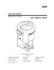
Installation<br />
Left Tilt<br />
Main Fold<br />
Right Tilt<br />
Outer Fold<br />
Lift Switch<br />
Spare<br />
Switches<br />
Foam<br />
Marker<br />
Switch<br />
Master<br />
On/Off<br />
Switch<br />
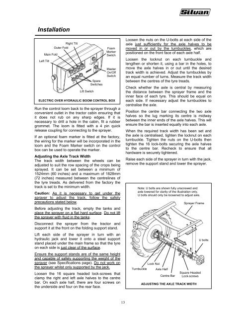
ELECTRIC OVER HYDRAULIC BOOM CONTROL BOX<br />
Run the control loom back to the sprayer through a<br />
convenient outlet in the tractor cabin ensuring that<br />
it does not rub on any sharp edges. If it is<br />
necessary to drill a hole in the cabin, fit a rubber<br />
grommet. The loom is fitted with a 4 pin quick<br />
release coupling for connecting to the sprayer.<br />
If an optional foam marker is fitted at the factory,<br />
the wiring for the marker will be incorporated in the<br />
loom and the Foam Marker switch on the control<br />
box can be used to operate the marker.<br />
Adjusting the Axle Track Width<br />
The track width between the wheels can be<br />
adjusted to suit the row spacing of the crops being<br />
sprayed. It can be set between a minimum of<br />
1524mm (60 inches) and a maximum of 1828mm<br />
(72 inches) measured between the centrelines of<br />
the tyre treads. As delivered from the factory the<br />
track is set to the minimum width.<br />
Caution: As it is necessary to get under the<br />
sprayer to adjust the track, follow the safety<br />
precautions stated below.<br />
Before adjusting the track, empty the tanks and<br />
place the sprayer on a flat hard surface. Do not lift<br />
the sprayer with fluid in the tanks.<br />
Loosen the nuts on the U-bolts at each side of the<br />
axle just sufficiently for the axle halves to be<br />
moved in or out by the turnbuckles, which are<br />
positioned on the front face of each axle half.<br />
Loosen the locknut on each turnbuckle and<br />
lengthen or shorten it, using a bar in the holes, to<br />
move the axle halves in or out until the desired<br />
track width is achieved. Adjust the turnbuckles by<br />
an equal number of turns. Measure the track width<br />
between the centres of the tyre treads.<br />
Check whether the axle is central by measuring<br />
the distance between the sprayer frame and the<br />
inner face of each tyre. This should be equal on<br />
each side. If necessary adjust the turnbuckles to<br />
centralise the axle.<br />
Position the centre bar connecting the two axle<br />
halves so the lug marking its centre is midway<br />
between the inner ends of the axle halves. This will<br />
ensure the bar is inserted equally into each axle.<br />
When the required track width has been set and<br />
the axle is centralised, tighten the locknut on each<br />
turnbuckle. Tighten the nuts on the U-bolts then<br />
tighten the 16 lock-bolts securing the axle halves<br />
to the centre bar. Recheck to ensure that all<br />
hardware is securely tightened.<br />
Raise each side of the sprayer in turn with the jack,<br />
remove the support stand and lower the sprayer.<br />
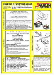
Note: U bolts are shown fully unscrewed and<br />
axle lowered for clarity of the illustration only.<br />
U bolts should only be loosened to adjust axle.<br />
Sprayer Frame<br />
Disconnect the sprayer from the tractor and<br />
support it at the front on the folding support stand.<br />
Lift each side of the sprayer in turn with an<br />
hydraulic jack and lower it onto a steel support<br />
stand placed under the main frame so that the tyre<br />
on each side is just clear of the surface.<br />
Ensure the support stands are of the same height<br />
and capable of safely supporting the weight of the<br />
sprayer (see Specifications page). Do not work on<br />
the sprayer whilst only supported by the jack.<br />
Loosen the 16 square headed lock-screws that<br />
clamp the right and left axle halves to the centre<br />
bar. On each axle half, there are four screws on<br />
the underside and four on the rear face.<br />
Turnbuckle<br />
Lock Nut<br />
Axle Half<br />
Centre Bar<br />
Square Headed<br />
Lock-screws<br />
ADJUSTING THE AXLE TRACK WIDTH<br />
U bolts<br />
13