Summerhouse Architectural Guidelines - charette | architects
Summerhouse Architectural Guidelines - charette | architects
Summerhouse Architectural Guidelines - charette | architects

You also want an ePaper? Increase the reach of your titles
YUMPU automatically turns print PDFs into web optimized ePapers that Google loves.
(8) The ARC reserves the right to require the submittal of other information, data, drawings and<br />
samples as deemed necessary. Submit all required items as directed by the Association<br />
Manager.<br />
B. Final Review: The following items must be submitted to the ARC for Final approval. (Note:<br />
It is the responsibility of the Owner to ensure that all copyrighted documents are approved by<br />
their originator for copying digitally and submitting for the review process. Designers who<br />
reproduce copyrighted designs by others shall be liable to the HOA for any action taken against<br />
the HOA by the copyright holder for approving such designs.)<br />
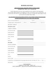
(1) A re-submittal of <strong>Summerhouse</strong> <strong>Architectural</strong> Review Submittal - Two with any updates<br />
in digital format.<br />
(2) Final Floor Plans, Elevations and Specifications in digital format (Minimum scale:<br />
1/8”=1’-0”, minimum sheet size 24”x36”) including:<br />
(3) Floor plan: Indicate all rooms, and sizes, along with square footage of the total enclosed<br />
living area. Show the finished floor elevation of the first floor. Submittals without finished<br />
floor height indicated will be rejected.<br />
(4) Roof plan: Indicate slopes, pitches, hips and gables.<br />
(5) Elevations: Provide front, rear, and side elevations showing building materials and finishes.<br />
Indicate maximum height of the principal structure and anticipated finished grades. A<br />
rendered elevation depicting material and colors of the primary façade may be requested by<br />
the ARC for more complicated elevation schemes.<br />
(6) Typical Wall Section: The section shall be made in a location that shows all floor to ceiling<br />
heights for all occupied spaces. (Two or more wall sections may be required) Indicate<br />
foundation condition, building materials, roof overhang, fascia, and decorative elements &<br />
other details as needed to convey the design. Ceiling heights must be indicated for all<br />
occupied levels of the home. One wall section must be cut through a typical window and a<br />
typical door.<br />
(7) Final Site Plan Prepare an <strong>Architectural</strong> Site Plan, in plan view, to scale 1:20 minimum or 1/8” =<br />
1’-0”, showing:<br />
1. Lot number and lot street address or street name if no number has been assigned.<br />
2. Boundary/property lines.<br />
3. Setbacks.<br />
4. Adjacent amenity features, roads lakes, sidewalks, etc. (where applicable).<br />
5. Easements within the boundary indicated.<br />
6. Public utilities for electric, telephone, and cable television, etc.<br />
7. Existing contours shown as dashed lines at 1-foot contour intervals indicating elevations<br />
relevant to mean sea level.<br />
8. Proposed finished contours indicated with solid lines.<br />
9. Identify FEMA zone and where applicable, designated Wetlands areas.<br />
10. Curb elevation at street.<br />
11. Location and species of trees that are 4” or larger existing & proposed to be removed.<br />
12. Polar orientation (North arrow).<br />
13. Location of construction related structures such as silt fence, toilet, dumpster, temporary<br />
construction entrance, construction fencing. This may be shown on a separate site drawing.<br />
14. Location of all proposed improvements to the property of any nature, including the main<br />
residence, driveways, walks, pools, patios, fireplaces, landscape walls, mailbox , outbuildings<br />
buried tanks or equipment, etc. Where sidewalks are provided of slatted wood and are<br />
intended to be pervious, details of their construction shall be shown.<br />
15. In a table on the drawing, show the square footage of the total site within property boundaries.<br />
In the same table show the square footage of the proposed vertical structure under roof<br />
extending to the roof drip line; show the square footage of all impervious pavement within the<br />
SUMMERHOUSE ON EVERETT BAY<br />
<strong>Architectural</strong> <strong>Guidelines</strong> – May 1, 2012 Edition<br />
Page 7 of 39