The EZ Guide 500 "How To Guide - New Holland PLM Portal
The EZ Guide 500 "How To Guide - New Holland PLM Portal
The EZ Guide 500 "How To Guide - New Holland PLM Portal

Create successful ePaper yourself
Turn your PDF publications into a flip-book with our unique Google optimized e-Paper software.
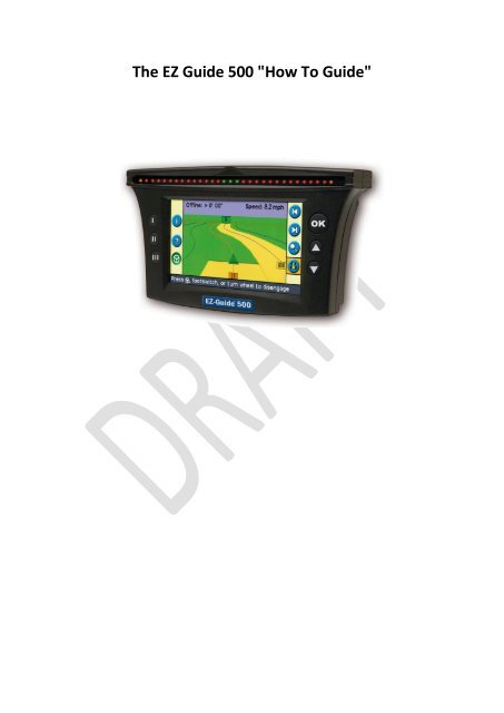
<strong>The</strong> <strong>EZ</strong> <strong>Guide</strong> <strong>500</strong> "<strong>How</strong> <strong>To</strong> <strong>Guide</strong>"
<strong>The</strong> <strong>EZ</strong> <strong>Guide</strong> <strong>500</strong> "<strong>How</strong> <strong>To</strong> <strong>Guide</strong><br />
Title<br />
Contents<br />
Section/Page<br />
<strong>EZ</strong> <strong>Guide</strong> 250 Table of contents<br />
1. User Mode...................................................................................................... 1 - 3<br />
2. Firmware<br />
2.1 Checking Software Version............................................................................. 2 - 3<br />
2.2 Check USB stick compatibility......................................................................... 2 - 4<br />
2.3 Downloading firmware................................................................................... 2 - 4<br />
2.4 Unzipping firmware and preparing USB stick................................................. 2 - 5<br />
2.5 Updating the Screen....................................................................................... 2 - 5<br />
3. Screen Unlock codes<br />
3.1 <strong>The</strong> <strong>EZ</strong> <strong>Guide</strong> <strong>500</strong> unlocks............................................................................... 3 - 6<br />
3.2 Upgrading EGNOS to OmniSTAR..................................................................... 3 - 6<br />
3.3 RTK/VRS Upgrading......................................................................................... 3 - 7<br />
3.4 VRA................................................................................................................. 3 - 7<br />
3.5 Entering an Unlock code................................................................................. 3 - 7<br />
4. Configuring EGNOS settings<br />
4.1 Satellites......................................................................................................... 4 - 8<br />
4.2 SBAS Positions................................................................................................ 4 - 8<br />
4.3 OnPath Filter.................................................................................................. 4 - 9<br />
5. Correctly Configuring OmniStar Settings<br />
5.1 OmniSTAR ID................................................................................................... 5 - 10<br />
5.2 Satellites from auto to EUSAT......................................................................... 5 - 10<br />
5.3 SBAS Positions................................................................................................. 5 - 10<br />
5.4 On Path Filter.................................................................................................. 5 - 11<br />
5.5 Convergence................................................................................................... 5 - 11<br />
6. Enabling the <strong>EZ</strong> <strong>Guide</strong> <strong>500</strong> for RTK<br />
6.1 Enabling RTK................................................................................................... 6 - 12<br />
6.2 Configuring PDL Radio..................................................................................... 6 - 13<br />
7. Installation of Equipment<br />
7.1 Correctly mounting the Antenna.................................................................... 7 - 16<br />
7.2 Upgrading the Antenna.................................................................................. 7 - 16<br />
7.3 Mounting the screen...................................................................................... 7 - 17<br />
8. <strong>EZ</strong> <strong>Guide</strong> <strong>500</strong> Add On Functions<br />
8.1 Adding an <strong>EZ</strong> Steer CAN connection............................................................... 8 - 18<br />
8.2 Adding a Coverage Switch.............................................................................. 8 - 18<br />
8.3 Adding a RADAR out Connection.................................................................... 8 - 20<br />
8.4 Adding an 'NMEA OUT' or 'RTCM IN' Cable.................................................... 8 - 20<br />
9. Data Management<br />
9.1 Field Management.......................................................................................... 9 - 22<br />
9.2 Deleting Coverage Logging............................................................................. 9 - 23<br />
9.3 Summary Reports........................................................................................... 9 - 24<br />
2
<strong>The</strong> <strong>EZ</strong> <strong>Guide</strong> <strong>500</strong> "<strong>How</strong> <strong>To</strong> <strong>Guide</strong><br />
1.User Mode<br />
Please Note: <strong>The</strong> <strong>EZ</strong> <strong>Guide</strong> <strong>500</strong> comes set on<br />
'Easy Mode'. Please set the 'User Mode' is set<br />
to 'Advanced' so that the various settings<br />
shown in this <strong>How</strong> <strong>To</strong> <strong>Guide</strong> can be accessed.<br />
<br />
On the run/main screen press the down<br />
arrow until you have selected the icon<br />
and then press OK. <strong>The</strong> 'Configuration'<br />
screen appears shown in {Figure 1.1].<br />
[Figure 1.1]<br />
<br />
Select 'User Mode'. <strong>The</strong> 'User Mode'<br />
screen appears shown in [Figure 1.2] and<br />
select Advanced by pressing OK.<br />
[Figure 1.2]<br />
2. Firmware<br />
Please Note: Firmware is the software<br />
that runs the <strong>EZ</strong> <strong>Guide</strong> screen.<br />
2.1 Checking Software Version<br />
Choose the Spanner icon. <strong>The</strong><br />
'Configuration' screen appears, as shown<br />
across in [Figure 2.1] press down to<br />
'About the <strong>EZ</strong>-<strong>Guide</strong>' and press OK.<br />
[Figure 2.1]<br />
<br />
<br />
<strong>The</strong> 'About the <strong>EZ</strong>-<strong>Guide</strong> screen will<br />
appear as shown in [Figure 2.2]. <strong>The</strong><br />
Firmware version is highlighted in red<br />
<strong>The</strong> current level of firmware is<br />
Version-5.10<br />
[Figure 2.2]<br />
3
<strong>The</strong> <strong>EZ</strong> <strong>Guide</strong> <strong>500</strong> "<strong>How</strong> <strong>To</strong> <strong>Guide</strong><br />
2.2 Check USB stick compatibility<br />
<br />
<br />
<br />
<br />
Please note that not all USB sticks are<br />
compatible with the <strong>EZ</strong>-<strong>Guide</strong> <strong>500</strong>. Some<br />
(Not all) FAT/FAT32 USB sticks are<br />
compatible with the <strong>EZ</strong>-<strong>Guide</strong> <strong>500</strong>.<br />
A green USB stick symbol will appear in<br />
the bottom left hand corner of the screen<br />
if the USB stick is compatible. This is<br />
shown in figure 2.3<br />
<strong>The</strong> colour of the USB stick icon will show<br />
the status of the USB stick as shown in<br />
Figure 2.4.<br />
Compatible USB sticks can be ordered<br />
through CNH Parts. Part No 73321221<br />
[Figure 2.3]<br />
[Figure 2.4]<br />
2.3 Downloading firmware<br />
<br />
<br />
<br />
<br />
<strong>EZ</strong>-<strong>Guide</strong> <strong>500</strong> firmware can be found in<br />
two different locations.<br />
1. Assist Home Page<br />
2. CNH Trimble Support Page<br />
2.3.1 ASIST home page<br />
Once logged into assist, click on the '<strong>EZ</strong>guide<br />
& FM1000 Software update<br />
information' link shown across in [Figure<br />
2.5] and choose <strong>EZ</strong> <strong>Guide</strong> <strong>500</strong>. This will<br />
open the link to save the file.<br />
2.3.2 CNH Trimble Support Page<br />
When logged into assist, choose 'Autoguidance<br />
support files, download<br />
equipment and advice' shown in [Figure<br />
2.6]. Click on the 'Auto-guidance' link.<br />
From the link that opens chose the<br />
'Trimble AutoPilot and <strong>EZ</strong> Support files'.<br />
[Figure 2.5]<br />
[Figure 2.6]<br />
Press<br />
here<br />
4<br />
[Figure 2.7]
<strong>The</strong> <strong>EZ</strong> <strong>Guide</strong> <strong>500</strong> "<strong>How</strong> <strong>To</strong> <strong>Guide</strong><br />
2.4 Unzipping firmware and preparing<br />
USB stick<br />
Once downloaded the ZIP file should then<br />
<br />
<br />
be copied to the root (first) folder of a<br />
compatible USB stick.<br />
<strong>The</strong> file must then be Unzipped before it<br />
can be used. This can be done by right<br />
clicking on the file and selecting 'extract<br />
here' as shown in [Figure 2.8].<br />
Note: <strong>The</strong> computer programme WinZip is<br />
needed to Unzip the file before the USB<br />
stick can be inserted into the <strong>EZ</strong>-<strong>Guide</strong><br />
<strong>500</strong>.<br />
[Figure 2.8]<br />
2.5 Updating the Screen<br />
Once the USB stick is inserted into the<br />
screen, the screen will recognise the<br />
newer firmware and the warning screen<br />
shown in [Figure 2.9] will appear.<br />
Pressing the OK button will go through<br />
the procedure of updating the screen this<br />
will only take a few minutes to do.<br />
[Figure 2.9]<br />
[Figure 2.10]<br />
5
<strong>The</strong> <strong>EZ</strong> <strong>Guide</strong> <strong>500</strong> "<strong>How</strong> <strong>To</strong> <strong>Guide</strong><br />
3. Screen Unlock codes<br />
3.1 <strong>The</strong> <strong>EZ</strong> <strong>Guide</strong> <strong>500</strong> unlocks<br />
‣ EGNOS level to OmniSTAR level<br />
‣ OmniSTAR level to RTK level<br />
‣ Variable Rate Application (VRA)<br />
3.2 Upgrading EGNOS to OmniSTAR<br />
<strong>The</strong> EGNOS to OmniSTAR Part Number is<br />
73313916. <strong>The</strong> dealer must place an order<br />
with SAP. <strong>The</strong>n he must send an e-mail to<br />
eugpsreceiverupgrade@cnh.com with<br />
following information :<br />
- <strong>EZ</strong> <strong>Guide</strong> <strong>500</strong> Serial Number<br />
- CNH Part Number<br />
- SAP Order Number<br />
| Serial Num | Part Num | Password<br />
+-----------------+-------------+----------------<br />
| 0225115282 | 55951 | 4BC77D97B<br />
Figure 3.1<br />
<br />
<strong>The</strong> serial number will then be sent back<br />
to the dealer which he will then used to<br />
enter in to the screen.<br />
<br />
<strong>The</strong> Customer must then purchase a<br />
subscription for a HP or XP correction<br />
signal from OmniSTAR (for info please<br />
visit www.omnistar.com)<br />
Note the serial number asked on the order<br />
form is the OmniSTAR User ID number<br />
Shown in Figure and not the screen serial<br />
number. Go to 'Configuration, System, GPS,<br />
GPS Setup, Omni* XP/HP, Continue'.<br />
Figure 3.2<br />
6
<strong>The</strong> <strong>EZ</strong> <strong>Guide</strong> <strong>500</strong> "<strong>How</strong> <strong>To</strong> <strong>Guide</strong><br />
3.3 RTK/VRS Upgrading<br />
<strong>The</strong> RTK upgrade code P/N is 73313917.<br />
This can be achieved by using the same<br />
method as the EGNOS to OmniSTAR.<br />
3.4 VRA<br />
<br />
<strong>The</strong> VRA upgrade follows the same<br />
method the OmniSTAR and RTK upgrade.<br />
Figure 3.3<br />
3.5 Entering an Unlock code<br />
<br />
<strong>To</strong> enter an unlock code then the user<br />
must go to 'Configuration, System,<br />
Password Upgrade' as shown from Figure<br />
3.3 to 3.5.<br />
Figure 3.4<br />
<br />
It is possible to check what features are<br />
unlocked on the screen by going to<br />
'Configuration, Status, Upgrade Options'.<br />
<strong>The</strong> upgrade options screen is shown<br />
across in Figure 3.6.<br />
Figure 3.5<br />
Figure 3.6<br />
7
<strong>The</strong> <strong>EZ</strong> <strong>Guide</strong> <strong>500</strong> "<strong>How</strong> <strong>To</strong> <strong>Guide</strong><br />
4. Configuring EGNOS settings<br />
4.1 Satellites<br />
Note: It is important to have the latest<br />
firmware in the screen, it doesn't mean that<br />
the screen is using the optimum setting and<br />
satellite configurations.<br />
Select ' , System, GPS, GPS Setup'.<br />
[Figure 4.1]<br />
<br />
<br />
<br />
Choose 'WAAS/EGNOS' shown in [Figure<br />
4.2]. In 'WAAS/EGNOS Settings' scroll<br />
down to 'Satellite' and press 'OK' as<br />
shown in [Figure 4.2].<br />
<strong>The</strong> optimum satellite used in the UK and<br />
Europe is 'EGNOS 120 AOR-E'.<br />
If you have correctly configured the<br />
screen as shown and still have a poor<br />
signal from 'EGNOS 120 AOR-E' then<br />
'EGNOS 124 ARTEMIS' can also be used.<br />
[Figure 4.2]<br />
4.2 SBAS Positions<br />
Note: 'SBAS positions' is a GPS quality<br />
indicator, This gives you the option of<br />
extending your operating hours by running<br />
the system when GPS satellites are less<br />
available and possibly providing lower<br />
position quality. Alternatively, you can select<br />
the best level of quality in order to achieve<br />
the maximum accuracy.<br />
[Figure 4.3]<br />
[Figure 4.4]<br />
8
<strong>The</strong> optimum setting for this will<br />
depend on what operation is being<br />
done in the field and the type of area<br />
that is being worked in. If high<br />
accuracy is needed then 'Favour<br />
accuracy' should be chosen.<br />
if low accuracy is being used such as<br />
mapping fields then balanced quality<br />
should be chosen. If the signal is poor<br />
then 'Favour availability' should be<br />
chosen.<br />
This setting can be changed by<br />
selecting the ' ' icon and choosing<br />
'SBAS Positions' as shown in [Figure<br />
4.6]<br />
[Figure 4.5]<br />
[Figure 4.6]<br />
3.3 On Path Filter<br />
<br />
<br />
<strong>The</strong> OnPath Filter should be set to<br />
match the area that the tractor is<br />
working in. Select Configuration ' ,<br />
System, GPS, GPS Limits' and then<br />
select 'OnPath Filter' as shown in<br />
figure 4.7.<br />
<strong>The</strong>re are 4 different settings as<br />
shown in figure 4.8. If the settings<br />
chosen does not match the area the<br />
screen is working in then the screen<br />
will tend to lose GPS signal quiet often.<br />
Figure 4.7<br />
Figure 4.8
<strong>The</strong> <strong>EZ</strong> <strong>Guide</strong> <strong>500</strong> "<strong>How</strong> <strong>To</strong> <strong>Guide</strong><br />
5 Correctly Configuring<br />
OmniStar Settings<br />
Going to 'Configuration, System, GPS, GPS<br />
Setup' and choose 'Omni* XP/HP'. <strong>The</strong> <strong>EZ</strong><br />
<strong>Guide</strong> will go through the 'OmniSTAR<br />
setup wizard'.<br />
5.1 OmniSTAR ID<br />
Figure 5.1<br />
<br />
<strong>To</strong> locate the OmniSTAR ID on an <strong>EZ</strong> <strong>Guide</strong><br />
<strong>500</strong>, choose 'Configuration' 'System',<br />
'GPS', 'GPS Setup', 'Omni*XP/HP', press<br />
'OK' and then 'Continue'. Figure 5.2 shows<br />
the location of the OmniSTAR ID.<br />
5.2 Satellites from auto to EUSAT<br />
Figure 5.2<br />
<br />
Go to 'Configuration, System, GPS, GPS<br />
Setup, Omni* XP/HP, Satellite'. Choose<br />
EUSAT from the list this is shown in Figure<br />
5.3.<br />
5.3 SBAS Positions<br />
Go to 'Configuration, Omni* XP/HP<br />
Positions'. From the three options choose<br />
the level of accuracy that is needed for<br />
the operation being performed.<br />
1. 'Favour Accuracy' provides the highest<br />
level of accuracy.<br />
2. 'Balanced Quality' trades potential<br />
accuracy for a slight increase in<br />
production time.<br />
10<br />
Figure 5.3<br />
Figure 5.4
<strong>The</strong> <strong>EZ</strong> <strong>Guide</strong> <strong>500</strong> "<strong>How</strong> <strong>To</strong> <strong>Guide</strong><br />
3. 'Favour Availability' extends production<br />
time further with more potential for<br />
reduced accuracy.<br />
5.4 On Path Filter<br />
<strong>The</strong> OnPath Filter should be set to match<br />
the area that the tractor is working in.<br />
Figure 5.5<br />
<br />
Select Configuration ' , System, GPS,<br />
GPS Limits' and then select 'OnPath Filter'<br />
as shown in figure 4.7.<br />
<strong>The</strong>re are 4 different settings as shown in<br />
figure 4.8. If the settings chosen does not<br />
match the area the screen is working in<br />
then the screen will tend to lose GPS<br />
signal quiet often.<br />
Figure 5.6<br />
5.5 Convergence<br />
Convergence time can be reduced by<br />
increacing the accuracy level at which the<br />
<strong>EZ</strong> <strong>Guide</strong> will be allowed to work at. <strong>To</strong><br />
change this then go to 'Configuration,<br />
System, GPS, GPS Setup, Omni* XP/HP,<br />
Continue, OK' and the 'Threshold for HP<br />
Favour Accuracy' screen appears. Change<br />
this figure to 150.<br />
Note: This reduces the time the operator<br />
needs to wait before he can start working in<br />
the field, it is important to note that this will<br />
reduce the accuracy level until the signal is<br />
fully converged.<br />
Figure 5.7<br />
Figure 5.8<br />
11
<strong>The</strong> <strong>EZ</strong> <strong>Guide</strong> <strong>500</strong> "<strong>How</strong> <strong>To</strong> <strong>Guide</strong><br />
6 Enabling the <strong>EZ</strong> <strong>Guide</strong> <strong>500</strong> for<br />
RTK<br />
6.1 Enabling RTK<br />
<strong>To</strong> recieve an RTK signal using an <strong>EZ</strong> <strong>Guide</strong><br />
<strong>500</strong>, the screen needs a PDL radio reciever<br />
to recieve the RTK signal. <strong>The</strong> PDL radio<br />
Part Number is ZTN62550-46-11.<br />
Note: Important notice regarding RTK base<br />
station ordering process. According to<br />
European laws, RTK Radio equipment<br />
ordered through CNH Parts & Service will<br />
have to be set up with the correct frequency<br />
or frequencies that the RTK Radio equipment<br />
owner has been granted permission for, from<br />
OFcom (Office of Communications). Each<br />
dealer must therefore sent the appropriate<br />
Frequency Configuration Sheet to<br />
eugpsreceiverupgrade@cnh.com. In all cases,<br />
it is necessary to follow this process to<br />
receive the RTK base set correctly otherwise,<br />
it will impact delivery. Contact your Parts<br />
Sales & Service Manager for more<br />
information.<br />
Before configuration of the PDL Radio to<br />
recieve the RTK signal please ensure the<br />
following has been completed.<br />
I. <strong>EZ</strong> <strong>Guide</strong> <strong>500</strong> unlocked to an RTK Level.<br />
II. One PDL radio has been ordered the<br />
Frequency Configuration Sheet has been<br />
emailed to<br />
eugpsreceiverupgrade@cnh.com<br />
Figure 6.0<br />
12
<strong>The</strong> <strong>EZ</strong> <strong>Guide</strong> <strong>500</strong> "<strong>How</strong> <strong>To</strong> <strong>Guide</strong><br />
6.2 Configuring PDL Radio<br />
<strong>The</strong>re are a number of steps needed to<br />
configure the PDL Radio reciever and the <strong>EZ</strong><br />
<strong>Guide</strong> <strong>500</strong>. these are;<br />
I. Connecting to the radio module<br />
II.<br />
III.<br />
IV.<br />
Load frequency file<br />
Configure settings<br />
Load firmware<br />
Figure 6.1<br />
Use PDL CONF utility Software available<br />
through the EST tool as shown in figure 6.1<br />
i. Connect to the radio module<br />
<br />
<br />
<br />
Use the PDL radio instructions that are<br />
included in the PDL Radio Kit to connect<br />
the PDL radio together shown in Figure<br />
6.2.<br />
Establish communication to the PDL radio<br />
using the 'Power On Capture'. This can be<br />
done by turning off the power to the PDL<br />
radio. <strong>The</strong>n select the power on capture<br />
mode as shown in figure 2.3 by left<br />
clicking the icon in the top left hand<br />
corner and choosing 'Capture Mode' and<br />
then 'Power On Capture'.<br />
<strong>The</strong> PDL radio must then be turned on<br />
within 10 seconds of choosing the 'Load'<br />
icon in the identification TAB, this is<br />
shown in figure 6.4. If this fails then<br />
repeat the procedure.<br />
Figure 6.2<br />
Figure 6.3<br />
Figure 6.4<br />
13
<strong>The</strong> <strong>EZ</strong> <strong>Guide</strong> <strong>500</strong> "<strong>How</strong> <strong>To</strong> <strong>Guide</strong><br />
<br />
ii. Load frequency file<br />
<strong>To</strong> load the frequency file, choose the<br />
'Program' icon, shown across in figure 6.5.<br />
<strong>The</strong> screen shown in Figure 6.6 will<br />
appear, choose the appropriate set file<br />
and select open.<br />
Note: <strong>The</strong> set file can be obtained through<br />
ASIST.<br />
Figure 6.5<br />
iii.<br />
<br />
Configure settings<br />
From the screen that appears plase check<br />
that the settings are correct in the<br />
identification tab as shown in figure 6.5<br />
Figure 6.6<br />
Note: <strong>The</strong>re is also the Possibility to enter<br />
the “Owner” name in the Identification TAB<br />
Please check that the radio parameters<br />
are set as shown across in figure 6.6<br />
under the Radio Link Tab.<br />
Under channel select choose the manual<br />
option.<br />
Enter the correct channel spacing 4800 =<br />
12.5 kHz Or 9600 = 25 kHz<br />
Figure 6.7<br />
14<br />
Figure 6.8
<strong>The</strong> <strong>EZ</strong> <strong>Guide</strong> <strong>500</strong> "<strong>How</strong> <strong>To</strong> <strong>Guide</strong><br />
<br />
Under the Radio Link, select the down<br />
arrow and select the channel frequency<br />
that is relevant to the owner.<br />
<br />
Under the 'Serial Interface' TAB check that<br />
the radio parameters are as shown across<br />
in figure 6.8<br />
Figure 6.9<br />
Note: Repeater must be selected only if you<br />
use the radio modem as repeater.<br />
iv.<br />
<br />
Load firmware<br />
In order to load the Radio firmware,<br />
communication with the radio must be<br />
establish. <strong>To</strong> do this then left click the<br />
icon in the top hand corner of the screen<br />
and choose 'Upgrade Modem Firmware'.<br />
Figure 6.10<br />
Figure 6.11<br />
Choose the correct firmware and then<br />
select open shown in figure 6.12. Choose 'Yes'<br />
from the Yes and No option that appears<br />
following on from this and confirmation will<br />
appear that the software have been installed<br />
successfully<br />
Figure 6.12<br />
15
<strong>The</strong> <strong>EZ</strong> <strong>Guide</strong> <strong>500</strong> "<strong>How</strong> <strong>To</strong> <strong>Guide</strong><br />
7 - Installation of Equipment<br />
7.1 Correctly mounting the Antenna<br />
<br />
<strong>The</strong> antenna should be mounted on the<br />
roof of the cab, in the centreline and as<br />
far forward as possible (without blocking<br />
the signal). <strong>The</strong> blue square shown in<br />
[Figure 7.1] displays where the antenna<br />
should be mounted. <strong>The</strong> antenna must be<br />
mounted as far forward as possible<br />
because once the tractor goes off line the<br />
further forward the antenna is the sooner<br />
the <strong>EZ</strong> <strong>Guide</strong>/<strong>EZ</strong> Steer can correct the<br />
error.<br />
[Figure 7.1]<br />
7.2 Upgrading the Antenna<br />
<br />
<br />
<strong>The</strong> <strong>EZ</strong> <strong>Guide</strong> <strong>500</strong> comes with an Ag15<br />
Antenna as standard. When the screen<br />
receiver is upgraded to an OmniSTAR level,<br />
included in the upgrade is a Z+ antenna<br />
which enables the screen to pick up an<br />
OmniSTAR/RTK signal.<br />
<strong>The</strong> Part Number for the upgrade kit is<br />
73313916. This includes the upgrade code<br />
and the new Z+ Antenna.<br />
[Figure 7.2]<br />
16
<strong>The</strong> <strong>EZ</strong> <strong>Guide</strong> <strong>500</strong> "<strong>How</strong> <strong>To</strong> <strong>Guide</strong><br />
7.3 Mounting the screen<br />
<br />
<strong>The</strong> screen is mounted to the front<br />
windscreen using two suction cups. <strong>The</strong><br />
part number for the suction cups are<br />
87301269. <strong>The</strong> dealer must manufacture<br />
a bar that joins the two suction cups and<br />
also attaches the RAM Mount to mount<br />
the screen as shown in figure 7.3.<br />
Figure 7.3<br />
Note: <strong>The</strong> <strong>EZ</strong> <strong>Guide</strong> <strong>500</strong> needs two<br />
suction cups to mount it to the tractor<br />
windscreen. One Suction cup is not<br />
sufficient to hold it.<br />
Figure 7.4<br />
<br />
If the <strong>EZ</strong> <strong>Guide</strong> <strong>500</strong> screen is being used<br />
with <strong>EZ</strong> Steer or AutoPilot then the most<br />
convenient way of mounting the screen is<br />
to fix it to the bracket on the right hand<br />
door shown in Figure 7.5 and figure 7.6.<br />
This is an ideal location because the<br />
Lightbar is not needed on the windscreen<br />
when using <strong>EZ</strong> Steer, also the <strong>EZ</strong> Steer<br />
engage button is in a more convenient<br />
location. <strong>The</strong> part number for the RAM<br />
mount is ZTN68042 (U bolts must be<br />
sourced locally).<br />
Figure 7.5<br />
17
<strong>The</strong> <strong>EZ</strong> <strong>Guide</strong> <strong>500</strong> "<strong>How</strong> <strong>To</strong> <strong>Guide</strong><br />
(5) <strong>EZ</strong> <strong>Guide</strong> <strong>500</strong> Add On Functions<br />
8.1 Adding an <strong>EZ</strong> Steer CAN connection<br />
<br />
<strong>The</strong> standard power cable that comes<br />
with the <strong>EZ</strong> <strong>Guide</strong> <strong>500</strong> includes the<br />
connection for connecting <strong>EZ</strong> Steer. In the<br />
<strong>EZ</strong> Steer kit the cable is included that goes<br />
from the <strong>EZ</strong> Steer controller to the <strong>EZ</strong><br />
<strong>Guide</strong> <strong>500</strong> power cable, this is shown in<br />
figure 8.1.<br />
Figure 8.1<br />
5.2 Adding a Coverage Switch<br />
Note: <strong>The</strong>re are three parts to adding a<br />
coverage switch to an <strong>EZ</strong> <strong>Guide</strong> <strong>500</strong> screen.<br />
<br />
<br />
<br />
8.2.1 Connect an interface cable to the<br />
Lightbar P/N 87301317<br />
8.2.2 Attach the female Weather Pack<br />
connector (supplied) to the wires of a<br />
switch (not supplied). <strong>The</strong> external switch<br />
has to be sourced locally and is not<br />
available from CNH parts.<br />
8.2.3 Configure the switch on the Lightbar.<br />
Figure 8.2<br />
Figure 8.3<br />
8.2.1 Connecting an interface cable to the<br />
Lightbar<br />
<br />
<strong>The</strong> coverage switch requires one of the<br />
following external interface cables with a<br />
3−pin Weather Pack connector:<br />
Figure 8.4<br />
18
<strong>The</strong> <strong>EZ</strong> <strong>Guide</strong> <strong>500</strong> "<strong>How</strong> <strong>To</strong> <strong>Guide</strong><br />
8.2.2 Attaching a female Weather Pack<br />
connector to the switch wires<br />
<br />
Strip about 1 cm (0.4 inches) of insulation<br />
off the switch wires. Thread each switch<br />
wire through a cable seal. Crimp terminal<br />
connectors to the ends of the wires with<br />
an appropriately−sized crimp tool or pliers<br />
and then solder the terminal connectors<br />
to the wire to ensure a secure connection.<br />
Insert the wires with terminal connectors<br />
and the cable seals into the appropriate<br />
holes on the female Weather Pack<br />
connector.<br />
Figure 8.5<br />
<br />
<br />
<strong>The</strong> Ground wire goes to Connector hole<br />
B<br />
<strong>The</strong> Switch wire goes to Connector hole C<br />
Figure 8.6<br />
NOTE: Ensure that you do not supply either<br />
wire with power. If necessary, use a relay to<br />
isolate the Lightbar from the power source.<br />
Figure 8.7<br />
8.2.3 Configure the switch on the Lightbar.<br />
<br />
<strong>To</strong> configure the coverage switch then<br />
choose Advanced Mode / System /<br />
Guidance / Coverage logging, select the<br />
Switch option. This is shown in figure 8.7.<br />
<strong>The</strong> switch can either be wired Active<br />
when the switch is Open (Active Low) or<br />
active when the switch is Closed, Active<br />
High.<br />
Figure 8.8<br />
Figure 8.9<br />
19
<strong>The</strong> <strong>EZ</strong> <strong>Guide</strong> <strong>500</strong> "<strong>How</strong> <strong>To</strong> <strong>Guide</strong><br />
8.3 Adding a RADAR out Connection<br />
<strong>The</strong> cable that is needed for RADAR<br />
Output is shown in figure 8.10, P/N is<br />
87301317 and this is same cable that is<br />
used for wiring a coverage switch.<br />
<br />
Connect the relevant cables to the<br />
controller and choose configurationsystem-radar<br />
output. Select On for Radar<br />
Enabled and then choose the appropriate<br />
Radar frequency Rate for the controller.<br />
Raven and Midtech controllers use 58.94<br />
Hz/mph (34.80 Hz/kph)<br />
Figure 8.10<br />
Figure 8.11<br />
8.4 Adding an 'NMEA OUT' or 'RTCM IN'<br />
Cable<br />
Note: 'NMEA out' is output from velocity,<br />
position, direction to 3rd party controllers (e.g.<br />
Vicon)<br />
'RTCM In' is input of external GPS data (e.g.<br />
From a 262 receiver)<br />
Figure 8.12<br />
<br />
<br />
<strong>To</strong> access the NMEA messages that are<br />
output, you require the all−port cable<br />
(P/N 64045) or the serial port add−on<br />
cable (P/N 63076). <strong>The</strong> cable needed to<br />
add NMEA Output or RTCM Input is P/N is<br />
73321231<br />
<strong>To</strong> configure NMEA output, select '<br />
/System/GPS/NMEA Output' shown in<br />
[Figure 8.12].<br />
20<br />
Figure 8.13
<strong>The</strong> <strong>EZ</strong> <strong>Guide</strong> <strong>500</strong> "<strong>How</strong> <strong>To</strong> <strong>Guide</strong><br />
Note: <strong>To</strong> be able to communicate, the<br />
parameters must match those of the device.<br />
<br />
<br />
<br />
<br />
Set the Lightbar port parameters. <strong>The</strong><br />
baud rate and the output rate need to<br />
be the same between the <strong>EZ</strong>-<strong>Guide</strong><br />
and the implement controller<br />
Select 'OK' Screen and then the<br />
'Message Selection' screen appears.<br />
Set the various message formats to On<br />
or Off, depending on whether they are<br />
required. <strong>The</strong>n select OK'<br />
Finally Configure the 'NMEA GGA<br />
output decimal places'.<br />
Figure 8.14<br />
Figure 8.15<br />
21
<strong>The</strong> <strong>EZ</strong> <strong>Guide</strong> <strong>500</strong> "<strong>How</strong> <strong>To</strong> <strong>Guide</strong><br />
9 Data Management<br />
NOTE: <strong>To</strong> take data from the <strong>EZ</strong> <strong>Guide</strong> <strong>500</strong> a<br />
compatible USB stick is needed. Please refer<br />
to page 3 for the compatible USB sticks<br />
section.<br />
9.1 Field Management<br />
<br />
<strong>The</strong> <strong>EZ</strong> <strong>Guide</strong> <strong>500</strong> can hold approximately<br />
60 fields in it internal USB. Once the 60<br />
fields have been used then the operator<br />
will have to transfer the field information<br />
or delete some of the fields to be able to<br />
continue. <strong>The</strong> USB left can be seen in the<br />
information tab on the home screen as<br />
'Storage' (hours).<br />
Figure 9.1<br />
9.1.1 Sending fields to a USB stick.<br />
While in Advanced mode going to<br />
'Configuration, data management,<br />
Manage Fields' and then select 'Send<br />
fields to USB Stick' , choosing this option<br />
will send all the field data from the screen<br />
on to a USB stick.<br />
Figure 9.2<br />
9.1.2 Deleting Fields<br />
Remove the USB stick and select<br />
'Configuration, Data Management,<br />
Manage Fields, Delete Selected fields'. It is<br />
then possible to choose what fields, what<br />
farms or what clients to delete.<br />
Figure 9.3<br />
22
<strong>The</strong> <strong>EZ</strong> <strong>Guide</strong> <strong>500</strong> "<strong>How</strong> <strong>To</strong> <strong>Guide</strong><br />
<br />
Deleting all the clients as shown in Figure<br />
will delete all the data from the screen.<br />
Deleting one client will delete just all the<br />
farms and fields for that client.<br />
9.1.3 Selecting fields from USB stick<br />
Figure 9.4<br />
<br />
When all the field data is saved on the<br />
USB stick this can be brought back on to<br />
the screen by selecting 'Get fields from<br />
USB'. It is now possible to select the<br />
required field from the USB Stick. <strong>The</strong><br />
field is now copied on to the Screen once<br />
again.<br />
Figure 9.5<br />
NOTE: This is useful when transferring fields<br />
from one <strong>EZ</strong> <strong>Guide</strong> to another.<br />
9.2 Deleting Coverage Logging<br />
<br />
Deleting field coverage logging is required<br />
when the operator wants to work in the<br />
same field that he had created before.<br />
Coverage logging is deleted, boundaries<br />
and obstacles remain this allows him to<br />
drive the same headland and AB lines<br />
without having to drive the boundary and<br />
create new AB Lines. <strong>To</strong> do this go to<br />
'Configuration, Data Management,<br />
Manage Fields, Delete Coverage Logging'.<br />
This will allow the user to select the field<br />
he wants to delete the coverage logging.<br />
Figure 9.6<br />
Figure 9.7<br />
Figure 9.8<br />
23
<strong>The</strong> <strong>EZ</strong> <strong>Guide</strong> <strong>500</strong> "<strong>How</strong> <strong>To</strong> <strong>Guide</strong><br />
9.3 Summary Reports<br />
<br />
<strong>To</strong> view field summary reports, insert a<br />
USB Stick and go to 'Configuration, Data<br />
Management, Summary Reports, Send<br />
Summary Reports to USB'. This will then<br />
allow you to choose the field that you<br />
want to view the summary report or send<br />
all the summary report to the USB Stick.<br />
Figure 9.9<br />
<br />
Plug the USB Stick in to the computer, go<br />
to "My Computer, USB Disk, AgGPS, Data,<br />
(Choose Relevant Client), (Choose<br />
Relevant Farm), (Choose Relevant Field),<br />
(Choose Relevant Event)" and open up the<br />
Word document called<br />
"EventSummary.rtf". In this word<br />
document there are 6 pages. <strong>The</strong><br />
information on them is as follows<br />
1. Event Details<br />
2. Map of Overlap<br />
3. Map of Height<br />
4. Map of Applied Rate<br />
5. Map of Speed<br />
6. Mapped Features<br />
<br />
Field area, Productive Area, and <strong>To</strong>tal<br />
Times are all included in the report along<br />
with other information. Figure 9.10<br />
Shows an example of the report.<br />
Figure 9.10<br />
24