Mx1100 Serial BTR for Remex Manual - Memex Automation
Mx1100 Serial BTR for Remex Manual - Memex Automation
Mx1100 Serial BTR for Remex Manual - Memex Automation

You also want an ePaper? Increase the reach of your titles
YUMPU automatically turns print PDFs into web optimized ePapers that Google loves.
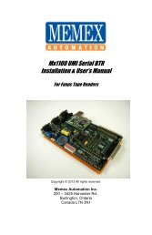
<strong>Mx1100</strong> UMI <strong>Serial</strong> <strong>BTR</strong><br />
Installation & User’s <strong>Manual</strong><br />
For <strong>Remex</strong> 7000 Series Tape Readers<br />
Copyright © 2013 All rights reserved.<br />
<strong>Memex</strong> <strong>Automation</strong> Inc.<br />
200 - 3425 Harvester Rd.,<br />
Burlington, Ontario<br />
Canada L7N 3N1
ii _ <strong>Mx1100</strong>UMI <strong>BTR</strong> User’s <strong>Manual</strong><br />
<strong>Mx1100</strong> UMI <strong>Serial</strong> <strong>BTR</strong>
Table of Contents<br />
Introduction.................................................................…...… v<br />
About this manual..............................................................v<br />
History of the <strong>BTR</strong>............................................................ v<br />
Installation Instructions......................................................... 1<br />
Package Contents...............................................................1<br />
Installing the <strong>Mx1100</strong> UMI <strong>BTR</strong>...................................... 2<br />
Operating The <strong>BTR</strong>........................................................... 5<br />
Layout Diagram of the <strong>Mx1100</strong> UMI <strong>Serial</strong> <strong>BTR</strong>............ 6<br />
Reference................................................................................. 7<br />
General Troubleshooting................................................... 7<br />
<strong>Memex</strong> Technical Support & Service..............................11<br />
User’s Notes.................................................................... 12<br />
Glossary................................................................................. 13<br />
Appendix A: Configuration & Settings............................. 17<br />
DNC Software Configuration In<strong>for</strong>mation...................... 17<br />
<strong>Mx1100</strong> Option Jumper Settings..................................... 17<br />
<strong>Mx1100</strong> <strong>Serial</strong> Port Pin Configuration............................ 18<br />
<strong>Serial</strong> Data Cable Configurations.................................... 18<br />
Appendix B: ASCII Code Reference Table........................ 19<br />
Contents _ iii
iv _ <strong>Mx1100</strong>UMI <strong>BTR</strong> User’s <strong>Manual</strong>
Introduction<br />
Thank you <strong>for</strong> purchasing the <strong>Mx1100</strong> UMI (Universal Machine<br />
Interface) <strong>BTR</strong>. At <strong>Memex</strong> we invest a great deal of ef<strong>for</strong>t in the<br />
design, manufacture and testing of each unit we build, and back it<br />
with a three-year limited warranty. We are confident you will find<br />
the <strong>Mx1100</strong> an important component of your shop floor<br />
communications system.<br />
About this <strong>Manual</strong><br />
This manual explains how to install and operate the <strong>Mx1100</strong>, and<br />
consists of the following sections:<br />
Installation Instructions explains how to install the<br />
<strong>Mx1100</strong> UMI <strong>BTR</strong> interface board.<br />
Reference contains a troubleshooting section, notes area<br />
and contact in<strong>for</strong>mation <strong>for</strong> customer service and<br />
technical support.<br />
Appendix A, Configuration & Settings provides<br />
in<strong>for</strong>mation <strong>for</strong> software (DNC) configuration, <strong>BTR</strong><br />
jumper settings and serial cable configuration (“pin-out”)<br />
charts.<br />
Appendix B, ASCII Table lists ASCII values in both<br />
Decimal and Hex <strong>for</strong>mats, their corresponding symbol,<br />
and keyboard key where applicable. This may be helpful<br />
in configuring DNC software in some cases.<br />
The History of the <strong>BTR</strong><br />
The “Behind the Tape Reader” board, or <strong>BTR</strong> as it is commonly<br />
called, is an electronic signal processor designed to emulate the<br />
function of a paper Tape Reader and provide an RS232 serial port<br />
as an alternate method of data entry to an NC or CNC control.<br />
RS232 is an international standard <strong>for</strong> electronic communications,<br />
and is a faster and more reliable means of data input than using<br />
Introduction _ v
punch tape or <strong>Manual</strong> Data Input (MDI). Originally, the only one<br />
way that a part program (the “G-code”) could be entered into a<br />
machine tool was through MDI mode, which allowed the program<br />
to be input using a keypad at the control. The MDI process was<br />
fine <strong>for</strong> small programs, but it was time consuming and error prone<br />
<strong>for</strong> longer programs. It took time to set up and to prove the MDI<br />
code be<strong>for</strong>e operation could commence. Machine flexibility was<br />
low, since each new program required time to input. With all the<br />
wasted time and lack of flexibility, it was not very long be<strong>for</strong>e<br />
someone invented an alternate <strong>for</strong>m of control input, the paper<br />
Tape Reader.<br />
The paper Tape Reader provided a faster, more reliable <strong>for</strong>m of<br />
data input to the numerical control. However, these Tape Readers<br />
were mechanical in nature, and required regular maintenance and<br />
care to per<strong>for</strong>m properly. Tape Readers allowed data and programs<br />
that were punched out on a paper tape to be read in by the control<br />
at a rate of approximately 300 to 400 characters per second. A few<br />
problems inherent in the Tape Reader are: it has limited ability to<br />
accept commands and in<strong>for</strong>m the operator of problems and status;<br />
it is prone to mechanical problems; it requires cleaning, lubrication<br />
and other maintenance; it has a limited capacity of 1000 feet (305<br />
metres) of tape. It was commonly suggested that a busy shop keep<br />
a spare reader in inventory in preparation <strong>for</strong> the time when one<br />
broke down.<br />
The process of punching data tapes (whether paper, Mylar or<br />
metal) was expensive, time-consuming and brought up storage<br />
concerns. Because of the absolute nature of a punched tape, the<br />
process had to be redone <strong>for</strong> every program revision. The<br />
programmer and operator had to work closely together to keep the<br />
tape accurate and up to date. Old tapes had to be filed or destroyed<br />
and the latest version had to be carefully marked and stored.<br />
Finally, the tape itself had to be handled with care since it was<br />
prone to damage.<br />
Later machine controls had a new mode of operation that allowed<br />
their Tape Reader’s “endless” spool of tape to surmount memory<br />
constraints. Originating on Numerical Controls (NC) that had no<br />
memory, Direct Numeric Control (DNC) allowed execution of a<br />
program while it was being read. This “drip-feed” method meant<br />
that the program was limited in size only by the length of tape<br />
used. This type of operation was very much appreciated later on<br />
with the advent of Computerized Numeric Controls (CNC).<br />
vi iv _ <strong>Mx1100</strong>UMI <strong>BTR</strong> User’s <strong>Manual</strong>
With true onboard memory the CNC had much greater capabilities<br />
and inevitably programs got longer and the need <strong>for</strong> more memory<br />
grew. With control memory being expensive and limited, DNC has<br />
remained the only way some modern manufacturers can operate.<br />
Tape Readers are still commonplace on modern controls today.<br />
However, thanks to serial DNC capabilities, many shops use Tape<br />
Readers <strong>for</strong> backup purposes only.<br />
The modern equivalent of a Tape Reader is the <strong>BTR</strong> interface<br />
board, which emulates paper Tape Readers. The <strong>Mx1100</strong> UMI<br />
<strong>BTR</strong> is a microcontroller-based interface board that allows<br />
communications with a machine control <strong>for</strong> the purposes of<br />
loading programs into memory or running DNC. <strong>BTR</strong>s generally<br />
connect to a computer and permit a programmer to send a<br />
complete, <strong>for</strong>matted program to the machine control. The machine<br />
then loads the program as if from tape, either to memory <strong>for</strong> later<br />
execution, or <strong>for</strong> immediate block-by-block execution (DNC).<br />
Because the <strong>Mx1100</strong> UMI <strong>BTR</strong> emulates the Tape Reader, the<br />
control really has no way of knowing that the source of the<br />
program is a computer port instead of a tape.<br />
The <strong>Mx1100</strong> UMI <strong>BTR</strong> eliminates punching of tape, has no<br />
moving parts, can handle transfer speeds that are 20 times that of a<br />
Tape Reader, uses the programmed (source) file, is less expensive<br />
than a Tape Reader, allows the Tape Reader to still be used,<br />
supports the use of the control’s punch capability, and does not<br />
require maintenance. It’s no wonder that the <strong>BTR</strong>, in combination<br />
with DNC software, has become the preferred alternative to using<br />
the Tape Reader and (in many cases) to upgrading CNC memory.<br />
While the <strong>Memex</strong> <strong>BTR</strong> gives the machine control the ability to<br />
receive programs from a PC, it has nothing to do with the specifics<br />
of what is being sent to the control. DNC software, or at the very<br />
least some <strong>for</strong>m of serial communications software, is responsible<br />
<strong>for</strong> transmitting the data to the control, and the control expects that<br />
data to be in a specific <strong>for</strong>mat. The part program must be <strong>for</strong>matted<br />
just as it would be <strong>for</strong> punching to tape, and the DNC software<br />
must be configured to send it as if it were a tape. The <strong>BTR</strong> acts<br />
only as a gateway or port to the control. The required program<br />
<strong>for</strong>mat is usually described in the control’s Operations <strong>Manual</strong>.<br />
Please consult the manual <strong>for</strong> in<strong>for</strong>mation on how to configure the<br />
part code programs <strong>for</strong> the control. Should you have any questions<br />
concerning <strong>BTR</strong>s, you are welcome to call us any time. See page<br />
11 or back cover <strong>for</strong> contact in<strong>for</strong>mation.<br />
Introduction _ vii v
viii _ <strong>Mx1100</strong> UMI <strong>BTR</strong> User’s <strong>Manual</strong>
Installation Instructions<br />
Unpacking the <strong>Mx1100</strong> UMI <strong>BTR</strong><br />
Package Contents<br />
<br />
<br />
<br />
<br />
<br />
1 x <strong>Memex</strong> <strong>Mx1100</strong> UMI <strong>Serial</strong> <strong>BTR</strong>......... Supplied<br />
1x <strong>Remex</strong> Interface Cable............................ Supplied<br />
1 x <strong>BTR</strong> / Tape Mode Switch...................... Supplied<br />
1 x Facit 4070 Punch Interface Cable.......... Supplied<br />
1 x Installation & User’s <strong>Manual</strong>................. Supplied<br />
Optional Items<br />
<br />
<br />
<strong>Serial</strong> Interface Cable (PC – <strong>BTR</strong>).............. Optional<br />
<strong>Serial</strong> Transfer (DNC) Software.....………. Optional<br />
Be<strong>for</strong>e You Begin<br />
Please read all instructions be<strong>for</strong>e proceeding. We recommended<br />
first making a temporary installation, becoming familiarized with<br />
the components and orientation of the assembly, testing the<br />
functionality, and then making the installation permanent by<br />
mounting the <strong>BTR</strong> and routing and securing the cables where they<br />
are out of harm’s way.<br />
Installation Instructions _ 1
Installing the <strong>Mx1100</strong> UMI <strong>BTR</strong><br />
General<br />
The <strong>Memex</strong> <strong>Mx1100</strong> UMI <strong>BTR</strong> installation procedure is<br />
straight<strong>for</strong>ward and relatively easy to complete – connect the <strong>BTR</strong> to<br />
the CNC where the Tape Reader was connected, optionally connect the<br />
Tape Reader to the <strong>BTR</strong>, and mount the <strong>BTR</strong> on the inside of the Tape<br />
Reader door. All the hardware and accessories are provided. All that’s<br />
needed are some basic skills and hand tools. Estimated time required:<br />
45 minutes.<br />
1. Prepare the site.<br />
Ensure that the Tape Reader and control are working properly<br />
be<strong>for</strong>e beginning the installation. When ready, turn OFF all power<br />
to the control, machine and your computer system.<br />
2. Access the Tape Reader.<br />
Locate the panel on your control that has the Tape Reader mounted<br />
on it. Open this door to gain access to the back of the Reader.<br />
3. Connect the <strong>BTR</strong>.<br />
Locate the 25-pin (db25) connector on the back of the Tape Reader<br />
that has a cable going to the CNC. Unplug this cable from the Tape<br />
Reader and plug it onto the <strong>BTR</strong>’s 25-pin (db25) connector on the<br />
right edge*, labelled “CONTROL”.<br />
4. Option: Connect the Tape Reader to the <strong>BTR</strong>.<br />
If you wish to enable the paper Tape Reader as well, take the new<br />
26-conductor ribbon cable and plug it onto the JP13 connector<br />
(labelled “TAPE IN”) in the centre of the right half of the <strong>BTR</strong>.*<br />
IMPORTANT: The red side of the cable goes on pin 1 of the<br />
connector (see diagram, page 6). Connecting this cable backwards<br />
may damage the <strong>BTR</strong> and/or the Tape Reader. Plug the other end<br />
of this cable into the back of the Tape Reader, where the original<br />
cable was disconnected in Step 3.<br />
Note:<br />
* All references made to objects located on the <strong>BTR</strong> are made with<br />
respect to the <strong>BTR</strong> being oriented horizontally so that the “Universal Machine<br />
Interface” label can be read at the bottom right. See diagram, page 6.<br />
2 _ <strong>Mx1100</strong> UMI <strong>BTR</strong> User’s <strong>Manual</strong>
5.<br />
Option: <strong>BTR</strong>/Tape Mode Switch.<br />
This switch is only needed if you want to enable the Tape Reader.<br />
It allows the <strong>BTR</strong> to be toggled back and <strong>for</strong>th between Tape mode<br />
(when you want to use the Tape Reader) and <strong>BTR</strong> mode (when<br />
you want to send files from your computer). It plugs onto JP3<br />
(labelled “SPI”) on the left side of the <strong>BTR</strong>, just behind the COM2<br />
port. To mount the switch to the CNC permanently, drill a ¼” hole<br />
in the cabinet and bolt it in place.<br />
Note: A second use of the Mode Switch is as a manual reset <strong>for</strong> the<br />
<strong>BTR</strong>. The <strong>BTR</strong> has an input buffer that will contain a small portion<br />
of the incoming part program until it finishes passing through. In<br />
the event of an abnormal interruption of data flow (machine error,<br />
etc.) where the part program must be stopped and resent, the <strong>BTR</strong><br />
buffer should be cleared. If a Tape Reader with reels is connected,<br />
flicking its mode switch will reset the <strong>BTR</strong>. If not, the <strong>BTR</strong>/Tape<br />
Mode Switch can be used as a reset switch.<br />
6. Option: Punch Cable.<br />
To punch part programs, parameters, etc. from the control to the<br />
computer, the control’s punch port can be connected to the <strong>BTR</strong>.<br />
Locate the punch port on the control. It is usually a 25-pin (db25)<br />
connector. Plug the 25-pin end of the Facit 4070 Punch interface<br />
cable into this port. Plug the other end of this cable onto the <strong>BTR</strong>’s<br />
JP4 connector (labelled “PUNCH IN”), just right of centre. The red<br />
side of the cable goes on pin 1 of the connector (see diagram on<br />
page 6). Remove jumper JP17 (labelled “PUNCH DISABLE”) in<br />
the upper right corner of the <strong>BTR</strong>.<br />
9. Configure the <strong>BTR</strong>.<br />
Set the jumpers on the <strong>BTR</strong> to configure the communications<br />
parameters required <strong>for</strong> your DNC system. The option jumpers,<br />
listed on page 17, include the following:<br />
A1 and A2 set the Baud rate. Typically 9600 baud (both<br />
jumpers ON) is used unless your cable doesn’t support that<br />
rate reliably. The RS232 specification supports 9600 Baud<br />
with a cable length up to 50 feet (15 metres), but it is often<br />
possible to exceed that. It’s important to use cable specifically<br />
designed <strong>for</strong> RS232 serial data, 22 AWG, twisted pair,<br />
stranded wire (not solid), shielded. Low capacitance (a rating<br />
of 11 to 15 pF per foot) is best. In any case, if you have a long<br />
cable run or are experiencing unreliable data transmission, try<br />
lowering the Baud rate. NOTE: CAT5 Ethernet cable is not<br />
suitable <strong>for</strong> use as serial data cable.<br />
Installation Instructions _ 3
A3 OFF adds hardware (RTS/CTS) handshaking. A3 ON is<br />
software (Xon/Xoff) only. Generally it is preferable to use<br />
both, which means setting A3 OFF and making sure your<br />
cable supports hardware handshaking (see Note 6 on page 9).<br />
A4 OFF uses the standard Xoff character, $13 Hex. Set A4<br />
ON if your DNC or terminal software uses $93 Hex <strong>for</strong> Xoff.<br />
A5 OFF uses the standard Xon/Xoff handshaking method (a<br />
single Xoff). Setting A5 ON sends a continuous stream of<br />
Xoff back to the computer until the next Xon. This enables the<br />
<strong>BTR</strong> to be used with some terminal programs that were<br />
intended <strong>for</strong> use with a modem, such as Procomm although<br />
we highly recommend the use of proper DNC software.<br />
A6 OFF will echo incoming data back to the PC <strong>for</strong> diagnostic<br />
purposes. Set A6 ON <strong>for</strong> normal use.<br />
A7 OFF is ISO data and ON converts incoming data to EIA<br />
<strong>for</strong>mat <strong>for</strong> controls that require EIA data.<br />
A8 overrides the Tape Reader’s selection of <strong>BTR</strong> or Tape<br />
mode. If the Tape Reader wasn’t reconnected to the <strong>BTR</strong>, or if<br />
the Tape Reader isn’t intended to be used often and the <strong>BTR</strong><br />
will usually in Tape mode, set A8 ON. (Remember to remove<br />
it when a tape needs to be read.)<br />
SG JMPR OFF = COM1 Signal Ground surge suppression.<br />
PWR P9 DBL ON activates power output on COM1’s pin 9,<br />
<strong>for</strong> use with devices such as buffers (see note on page 18).<br />
10. Connect to the Computer.<br />
Connect a serial cable from the 9-pin COM1 on the <strong>BTR</strong> to the<br />
computer’s serial port (see page 18 <strong>for</strong> cable configurations).<br />
11. Test the Functionality.<br />
Refer to “Operating the <strong>Mx1100</strong> UMI <strong>BTR</strong>” (page 5), and if<br />
necessary, “Reference” (page 7).<br />
12. Mark and Reroute the Cables.<br />
Mark the connectors and cables to ensure proper reconnection.<br />
Disconnect the cables and route them neatly where they won’t be<br />
pinched, etc. Mount the <strong>BTR</strong> in a safe location inside the control<br />
cabinet. Carefully reattach and secure all cables with cable ties.<br />
4 _ <strong>Mx1100</strong> UMI <strong>BTR</strong> User’s <strong>Manual</strong><br />
2 _ <strong>Mx1100</strong> UMI <strong>BTR</strong> User’s <strong>Manual</strong>
Operating the Mx1000 UMI <strong>Serial</strong> <strong>BTR</strong><br />
To use the control’s new serial port:<br />
Make sure the cables are connected correctly and prepare your DNC<br />
software. Press Reset on the Fanuc control to reset the <strong>BTR</strong> and ensure<br />
that no residual data is present in its input buffer. If <strong>BTR</strong> option jumper<br />
A8 is OFF (switch enabled), and the Tape Reader is connected, switch<br />
the <strong>BTR</strong> into <strong>BTR</strong> mode either by turning off the Tape Reader or by<br />
switching the Tape Reader to Release mode. Start an upload to the<br />
control from your DNC software, and then load a program at the<br />
control as if from tape. You can put the control in Tape mode and press<br />
READ or INPUT to load the program into memory (if it will fit), or put<br />
the control in DNC (or External) mode and press Cycle Start to run it in<br />
DNC mode – also known as “drip feeding”. (These mode names and<br />
key names will vary according to the control model.)<br />
If you have any difficulty or concerns, please refer to “General<br />
Troubleshooting” on page 7.<br />
Helpful hints<br />
<br />
<br />
Adding a couple of Carriage Returns to the end of the file will<br />
ensure that the entire file is transmitted. Some combinations of<br />
DNC software and CNC control sometimes miss the end of a<br />
file, so it’s a good idea to provide some harmless extra<br />
characters as a buffer.<br />
The <strong>BTR</strong> responds to the Break character by resetting and<br />
clearing its buffer. The Break character is ASCII value 3, or<br />
HEX 03 (see Appendix B, page 19). If your DNC software can<br />
be configured to send control codes, it’s a good idea to have it<br />
send a Break character at the beginning of every g-code<br />
program it sends. This will guarantee that the <strong>BTR</strong> buffer is<br />
reset and ready <strong>for</strong> a new program each time, regardless of<br />
whether the CNC didn’t properly finish reading the previous<br />
one. (The Break character will not be passed through to the<br />
CNC, and the start of the program following it will wait while<br />
the <strong>BTR</strong> is resetting.)<br />
Installation Operating Instructions the <strong>Mx1100</strong> _ 35
COM 1<br />
Connect to<br />
Computer<br />
Reset<br />
Configuration<br />
Jumpers A1-A8<br />
SP1<br />
Mode Switch<br />
Connector<br />
JP22, SG JMPR<br />
Disables Signal<br />
Ground Surge<br />
Suppression on COM1<br />
J7, Power Terminal<br />
JP33, PWR P9 DBL<br />
Enable power output on<br />
COM1 pin 9<br />
JP4, PUNCH IN<br />
26-pin header - Connect<br />
to CNC's punch port<br />
Pin 1 indicator: Cable's red stripe always<br />
goes on whichever side has this mark<br />
1 1<br />
JP17<br />
Punch Disable<br />
P2, CONTROL<br />
25-pin connector -<br />
Connect to CNC<br />
COM1<br />
JP16, +24TR<br />
24 Volt selector<br />
A1<br />
A2<br />
A3<br />
A4<br />
A5<br />
A6<br />
A7<br />
A8<br />
RESET<br />
LOAD<br />
MEMEX ETHERNET MODULE<br />
JP10, REG ENBL<br />
24 Volt regulator<br />
Power<br />
Status<br />
Status LEDs<br />
JP13, TAPE IN<br />
26-pin header - Connect to<br />
Tape Reader (Optional)<br />
1<br />
1<br />
1<br />
Cable keyway.<br />
If cable has no key,<br />
be extra careful<br />
orienting the cable<br />
+7-24V<br />
+5V<br />
-GND<br />
JP16<br />
+24TR<br />
J7<br />
JP22<br />
SG JMPR<br />
PWR P9 DBL<br />
REG ENBL<br />
JP10<br />
S/N: 030301-<br />
MEMEX ELECTRONICS INC.<br />
(C)2003<br />
PWR ON<br />
STATUS<br />
TX<br />
COM1 COM2<br />
1<br />
FANUC CONTROL A<br />
CONTROL B<br />
JP8<br />
JP7<br />
TAPE READER B<br />
UNIVERSAL MACHINE INTERFACE<br />
MX1100 R3<br />
MADE IN CANADA<br />
WWW.MEMEX.CA<br />
RX<br />
RTS<br />
CTS<br />
TX<br />
RX<br />
RTS<br />
CTS<br />
FANUC TAPE READER A<br />
PUNCH DISABLE<br />
JP17<br />
JP18<br />
+5TR<br />
1<br />
JP18, +5TR<br />
5 Volt selector<br />
PUNCH IN JP4<br />
TAPE IN JP13<br />
SP1 JP3<br />
IMPORTANT: If punch cable is connected, JP17 must<br />
IMPORTANT: If +5TR is ON, then both<br />
be OFF; If punch cable is not connected, JP17 must be ON.<br />
+24TR and REG ENBL must be OFF;<br />
If +5TR is OFF, then both +24TR and REG ENBL<br />
must be ON. (See Note 1 on Page 7.)<br />
1<br />
JP5<br />
JP6<br />
6 _ <strong>Mx1100</strong> UMI <strong>BTR</strong> User’s <strong>Manual</strong><br />
Layout of the <strong>Mx1100</strong> UMI <strong>Serial</strong><br />
<strong>BTR</strong>
Reference<br />
This chapter contains troubleshooting hints and in<strong>for</strong>mation about<br />
<strong>Memex</strong> Technical Support and Service.<br />
General Troubleshooting<br />
The <strong>Mx1100</strong> UMI <strong>BTR</strong> is designed to install easily and quickly.<br />
However, experiencing difficulty in the procedures, please check the<br />
following to isolate and resolve the problem.<br />
1. Check that the “PWR ON” LED on the <strong>BTR</strong> (leftmost LED in<br />
the LED block at bottom centre*) is on and bright.<br />
The RTS LED <strong>for</strong> COM1 should also be on. If there is no power to<br />
the <strong>BTR</strong>, ensure that the cables from the Control (and from the<br />
Tape Reader if connected) are oriented properly and are well<br />
secured. Also, check that one of the following is true:<br />
a) The “+5TR” jumper (JP18 at bottom right) is ON and the<br />
“+24TR” jumper (JP16 at middle left) and “REG ENBL”<br />
(JP10 near middle bottom) are OFF; -orb)<br />
The “+5TR” jumper (JP18) is OFF and the “+24TR” jumper<br />
(JP16) and “REG ENBL” (JP10) are ON<br />
In case “a” above, the <strong>BTR</strong> is sourcing 5 volts from the CNC; in<br />
case “b” it is sourcing 24 volts and reducing it to 5 volts.<br />
Typically 5V (setting “a”) is used with a Fanuc control.<br />
Note: The default power source setting is “a” above, 5 volts.<br />
However, in some CNCs the 5-volt supply has faded to below<br />
the threshold that will power the <strong>BTR</strong>. If the <strong>BTR</strong> won’t power<br />
on, try using 24 volts by setting the jumpers as in “b” above.<br />
Note:<br />
* All references made to objects located on the <strong>BTR</strong> are made with<br />
respect to the <strong>BTR</strong> being oriented horizontally so that the “Universal Machine<br />
Interface” label can be read at the bottom right. See diagram, page 6.<br />
Reference _ 7
2. Alternate source of power.<br />
If the PWR LED still does not come on, carefully find a source of<br />
power on the control between 7 and 24VDC and wire it in to<br />
screw-down terminal block J7 at the lower left corner. When power<br />
is brought in through the terminal block, the jumpers must be set<br />
as in “b” above.<br />
3. Check that the <strong>BTR</strong> is working properly.<br />
When the control is powered up or reset, the <strong>BTR</strong>’s STATUS LED<br />
(2 nd LED in LED block at middle bottom) should blink. One blink<br />
indicates that the <strong>Mx1100</strong> is in <strong>BTR</strong> Mode. This means that it is<br />
ready to receive in<strong>for</strong>mation through the serial port and to send it<br />
to the control. Two blinks indicate that the <strong>Mx1100</strong> is in TAPE<br />
Mode. This means that it is ready to pass in<strong>for</strong>mation through the<br />
<strong>BTR</strong> from the Tape Reader to the Control. (The leftmost TX LED<br />
will also blink, as the <strong>BTR</strong> sends out a status message on its<br />
COM1 port during power up.) With most Tape Readers, turning<br />
the Tape Reader on/off or switching it between Load and Release<br />
will switch the <strong>BTR</strong> between modes.<br />
4. Check the status message.<br />
When the <strong>BTR</strong> is powered on or reset, it sends a short message on<br />
its COM1 port, indicating which mode it’s in. The STATUS and<br />
first TX LEDs will blink during output. If the computer is properly<br />
connected, and your DNC software is configured to match the<br />
<strong>BTR</strong> communication settings and is set to receive a file, it should<br />
be possible to capture and read the status message. If the message<br />
is clearly readable then the <strong>BTR</strong>’s communications are good, and<br />
so is the cable, the settings, the computer and the DNC software.<br />
NOTE: Some versions of the <strong>BTR</strong> require the A6 jumper to be off<br />
(echo enabled) <strong>for</strong> the status message to be sent back to the PC on<br />
Power On.<br />
5. The Status and Tx LEDs flash but there is no status message.<br />
First the computer has to be watching <strong>for</strong> the status message with<br />
DNC software, or at least with a terminal program or utility. After<br />
installing your software, verify that the correct communication<br />
parameters are set and check that the correct computer COM port<br />
is being used. Check that the BAUD RATE is properly set and<br />
matches the baud rate on the <strong>BTR</strong> (check option jumpers A1 and<br />
A2 – see pg. 17) and that the STOP BITS are set to 1. Make sure<br />
that the cable connecting the <strong>BTR</strong> to the computer is a properly<br />
configured RS-232 serial data cable and that it is properly<br />
connected (see Step 6 below). Also verify that the PC’s COM port<br />
is functioning properly.<br />
8 _ <strong>Mx1100</strong> UMI <strong>BTR</strong> User’s <strong>Manual</strong>
6. Check the serial data cable and handshaking settings.<br />
First, make sure the cable matches the appropriate diagram under<br />
“<strong>Mx1100</strong> UMI <strong>BTR</strong> Cable Configurations” (page 18).<br />
Second, make sure the cable, <strong>BTR</strong> settings and software settings<br />
match with regard to handshaking method. If using software<br />
handshaking (Xon/Xoff) only (see table A on page 18), make sure<br />
that <strong>BTR</strong> Jumper A3 is ON and your DNC software is set <strong>for</strong><br />
Xon/Xoff handshaking only. If using hardware handshaking (see<br />
table B on page 18), make sure that <strong>BTR</strong> Jumper A3 is OFF, your<br />
DNC software is set <strong>for</strong> RTS/CTS and Xon/Xoff handshaking, and<br />
the cable supports it by having the wires <strong>for</strong> RTS and CTS<br />
connected <strong>for</strong> a total of five wires connected at each end. (Note:<br />
Software handshaking can be used with a hardware handshaking<br />
cable, but not the other way around.)<br />
Third, make sure every wire connection at each end of the cable is<br />
solid, there are no breaks in the wires, no wire insulation is pulled<br />
back far enough to allow bare wire to touch another wire or any<br />
other metal parts, and no solder or debris is touching more than<br />
one pin. If everything looks good at the ends, it may be necessary<br />
to use a multimeter to determine whether there is a break or a short<br />
in the wires somewhere along the length of the cable.<br />
If a hardware handshaking cable is being used, the leftmost CTS<br />
LED (in the STATUS LED bank at bottom centre of the <strong>BTR</strong>) will<br />
light up when a properly configured cable is connected between<br />
the <strong>BTR</strong> and a computer and both are powered on. The leftmost<br />
RTS LED will always be on, indicating that the <strong>BTR</strong> is active and<br />
the port is ready. Regardless of which type of handshaking is being<br />
used, the leftmost RX LED will blink when data is sent to the<br />
<strong>BTR</strong>, and the leftmost TX LED will blink during any Xon/Xoff<br />
handshaking that might occur during the send.<br />
7. The whole file sends be<strong>for</strong>e pressing Cycle Start.<br />
The most common cause of this is incorrect handshaking settings.<br />
Refer to Note 6 above. In addition, some terminal programs expect<br />
the XOFF character, normally Hex 13, to include even parity,<br />
making it Hex 93. Try setting jumper A4 ON (see page 17).<br />
Reference _ 9
8. A CNC error occurs shortly after pressing “Cycle Start”.<br />
Try removing the CR (carriage return) characters from the<br />
program. Some controls only accept “pure” ISO or EIA code,<br />
which does not contain CR characters. Also try changing <strong>BTR</strong><br />
jumper A7 in case it’s a matter of ISO / EIA <strong>for</strong>mat mismatch.<br />
9. The control generates a Tape Vertical (TV) alarm.<br />
Tape Vertical checking was a way that controls verified the<br />
accuracy of the program code they read in through the Tape<br />
Reader. It is usually an option and does not apply when you are<br />
using a <strong>BTR</strong>. Turn this option off in the control’s parameters.<br />
10. The control generates a Tape Horizontal (TH) alarm.<br />
Tape Horizontal is equivalent to Even parity. Use Even parity<br />
when sending the programs from the terminal or PC. Also see<br />
Notes 7 and 8 above – jumper A4 and/or A7 may resolve this.<br />
11. The Power LED lights but the STATUS LED doesn’t flash.<br />
Check the supply voltage to the <strong>BTR</strong>. If using a 5VDC supply and<br />
it is less than 4.6VDC, the <strong>BTR</strong> may actually be protecting itself<br />
from under-voltage. Find a better 5V supply, or switch to 24V (see<br />
Note 1 “b”) or use the screw-down terminal in the bottom left<br />
corner with a supply of 7 to 24VDC. Always be sure to set up the<br />
power jumpers correctly (see Notes 1 and 2).<br />
12. Other machine errors:<br />
Ensure that you have added in the proper tape codes at the<br />
beginning and/or end of your program. Some machines require that<br />
you have a % sign as the first and/or last character in your<br />
program. Check your CNC Operator’s <strong>Manual</strong> <strong>for</strong> any termination<br />
characters that may be required.<br />
13. What if the <strong>BTR</strong> “Locks Up”<br />
Near the upper left corner of the <strong>BTR</strong> are the four pins labelled<br />
RESET and LOAD. Of those four pins, the top two are the reset<br />
pins. Momentarily shorting the two RESET pins by touching them<br />
with a metal object such as a screwdriver or coin (while the power<br />
is on) will reset the <strong>BTR</strong> and make the STATUS LED flash. This<br />
action is the equivalent of pressing the reset button on a PC. This<br />
should not have to be done on a regular basis, but, as with anything<br />
electronic, lockup can happen.<br />
10 8 _ <strong>Mx1100</strong> UMI <strong>BTR</strong> User’s <strong>Manual</strong>
<strong>Memex</strong> Technical Support & Service<br />
In case of technical difficulty with the <strong>Mx1100</strong> UMI <strong>BTR</strong>, be sure to<br />
review the troubleshooting section of this manual prior to calling <strong>for</strong><br />
technical support. If the issue cannot be resolved after reading through<br />
the troubleshooting section, please contact <strong>Memex</strong> <strong>Automation</strong><br />
Technical Support at 1-905-635-3042. Page 12 of this manual may be<br />
used to record technical in<strong>for</strong>mation, service advice, etc. as needed.<br />
If you have any other questions or concerns, need answers to technical<br />
questions, or need in<strong>for</strong>mation about <strong>Memex</strong> products and/or services,<br />
please contact your local <strong>Memex</strong> dealer, or contact <strong>Memex</strong><br />
<strong>Automation</strong>.<br />
<strong>Memex</strong> <strong>Automation</strong> Inc.<br />
200 – 3425 Harvester Rd.,<br />
Burlington, Ontario L7N 3N1<br />
Canada<br />
Phone: 905-635-1540<br />
Fax: 905-631-9640<br />
Web: www.memex.ca<br />
Email: sales@memex.ca<br />
support@memex.ca<br />
<strong>Memex</strong> Customer Support & Service _ 11
Notes<br />
12 _ <strong>Mx1100</strong> UMI <strong>BTR</strong> User’s <strong>Manual</strong>
Glossary<br />
ANSI American National Standards Institute. The official US<br />
agency and voting representative <strong>for</strong> ISO. This institute develops<br />
in<strong>for</strong>mation exchange standards above 50 Mbps.<br />
ASCII American Standard Code <strong>for</strong> In<strong>for</strong>mational Interchange. A<br />
seven bit alphanumeric code used extensively in data communications.<br />
A parity bit is often added to the seven-bit code <strong>for</strong> error detection.<br />
See Appendix B, page 19 <strong>for</strong> a table of ACSII values.<br />
ASYNCHRONOUS TRANSMISSION The transmission of<br />
characters separated by time intervals that vary in length, usually in<br />
accordance with the key entries of a terminal operator. Start and stop<br />
bits are used to identify (frame) the beginning and end of the<br />
asynchronously transmitted character.<br />
BAUD RATE The rate at which a signal is changed or modulated.<br />
Refers to the number of bits transmitted per second.<br />
<strong>BTR</strong> Behind the Tape Reader. An electronic input device that<br />
emulates a Tape Reader’s signals on a machine control, usually<br />
converting serial communications to parallel Tape Reader signals.<br />
CNC Computerized Numerical Control. An industrial computer that<br />
is used to control the movement of a machine. A CNC usually uses<br />
programs coded with G-codes and M-codes.<br />
CONTROL Refers to a Computerized Numerical Control (CNC).<br />
CTS Clear To Send. One of the control lines used in RS232<br />
communication. Found on pin 4 or 5 on a DB25 and pin 7 or 8 on a<br />
DB9 depending whether the port is DTE or DCE.<br />
DCE Data Communication Equipment. Typically a modem or data<br />
set used to interface a terminal or computer to the telephone lines.<br />
Glossary _ 15 _ 13
DNC Direct/Distributed Numeric Control. A means of<br />
communicating or “drip feeding” a program to a CNC through a Tape<br />
Reader or serial interface. The program code is immediately executed,<br />
block by block, as it is read by the control.<br />
DTE Data Terminal Equipment. In data communications, it is an<br />
end user or termination circuit, typically a terminal or computer.<br />
ECHO A reflected signal. In<strong>for</strong>mation is sent back to the transmitter<br />
from the receiver, often <strong>for</strong> verification purposes.<br />
EIA Electronic Industries Alliance. A United States organization of<br />
manufacturers that establishes and recommends industrial standards.<br />
They developed the EIA standard code used in early NC and CNC<br />
communications. Also refers to a <strong>for</strong>m of 7-bit ASCII with data<br />
encryption and Odd parity, used largely on CNCs.<br />
FRAMING The procedure used to identify the beginning and end of a<br />
group of data bits.<br />
FRAMING ERROR An error that occurs when a receiver loses<br />
synchronism to the incoming data.<br />
G CODE The instructions used to dictate the movement of a machine.<br />
A list of these codes is commonly called a “part program”.<br />
HANDSHAKING A process that regulates the flow of data between<br />
two devices. Also called “flow control”.<br />
HARDWARE HANDSHAKING Handshaking (flow control) by use<br />
of the RTS and CTS control lines on an RS232 serial interface.<br />
ISO International Standards Organization. One of the world’s<br />
largest standards organizations. Also refers to a <strong>for</strong>m of 7-bit ASCII<br />
with data encryption and Even parity, used largely on CNCs.<br />
LOCAL ECHO Refers to when a terminal is configured to internally<br />
route its transmitted character around to its receiver section <strong>for</strong> display.<br />
18 14 _ <strong>Mx1100</strong> UMI <strong>BTR</strong> User’s <strong>Manual</strong>
MODEM A contraction of modulator/demodulator. The modem<br />
converts a computer’s digital bit stream into an analog signal suitable<br />
<strong>for</strong> telephone lines and vice versa.<br />
PAPER TAPE A media of part program storage. Holes were punched<br />
in a one-inch paper tape to represent G codes. These tapes were then<br />
read through a Tape Reader to be loaded into machine control memory.<br />
PARITY An error detection method whereby a single bit is added to a<br />
group of bits to make the total number of 1 bits either even or odd<br />
(depending on the type of parity; even or odd).<br />
PART PROGRAM A list of G codes that control the movement of<br />
the machine. May be typed into the machine control or produced as a<br />
computer text file and transmitted to the control.<br />
PARITY ERROR Indicates that the total number of 1 bits in a<br />
received character does not agree with the type of parity expected.<br />
RS232-C An asynchronous serial interface standard that specifies an<br />
electrical, functional, and mechanical interface specification between<br />
data communication devices.<br />
RTS Request To Send. One of the control lines used in RS232<br />
communication. Found on pin 4 or 5 on a DB25 and pin 7 or 8 on a<br />
DB9 connector depending on whether the port is DCE or DTE.<br />
RTS/CTS Hardware handshaking (flow control) using the RTS and<br />
CTS control lines.<br />
Rx Receive Data. Refers to the input <strong>for</strong> the data signal.<br />
SG Signal Ground. Refers to the ground <strong>for</strong> the data signal. Not the<br />
same as the cable’s shield ground or a device’s frame ground.<br />
START BIT The first bit used to frame an asynchronously<br />
transmitted character. Its logic level is a 0 (space).<br />
Glossary _ 15
STOP BIT The last bit used to frame an asynchronously transmitted<br />
character. Its logic level is a 1 (mark).<br />
SYNCHRONOUS TRANSMISSION High-speed communication<br />
whereby data characters are sent in direct succession to each other<br />
without the use of Start and Stop bits.<br />
TAPE READER An input device used on CNC Machines and other<br />
industrial equipment. Used to read coded data on a punched tape. Older<br />
Tape Readers were a mechanical device, whereas newer ones use<br />
optical devices that sense light passing through the holes in the tape.<br />
TERMINAL An input/output device used by an operator to<br />
communicate with a host computer. It consists of a keyboard and a<br />
display to monitor alphanumeric characters entered at the keyboard or<br />
received from a remote device.<br />
TERMINAL SOFTWARE Computer software that enables a<br />
computer to act as a terminal, usually used with modems. Can be used<br />
to exchange data over a serial cable between two computers or a<br />
computer and a machine control, but does not provide the level of flow<br />
control necessary to prevent dangerous miscommunications with a<br />
machine control. Specific purpose DNC software is highly preferable.<br />
TIME-OUT ERROR An error that occurs when a device fails to<br />
respond to a message within an expected period of time.<br />
Tx Transmit Data. Refers to the output <strong>for</strong> the data signal.<br />
XOFF Transmit Off. A device control character (DC3 or $13 hex)<br />
used to control the flow of data between two devices. XOFF is used<br />
together with XON as a handshake.<br />
XON Transmit On. A device control character (DC1 or $11 hex)<br />
used to control the flow of data between two devices. XON is used<br />
together with XOFF as a handshake.<br />
XON/XOFF Software handshaking using the XON and XOFF control<br />
characters.<br />
18 16 _ <strong>Mx1100</strong> UMI <strong>BTR</strong> User’s <strong>Manual</strong>
Appendix A: Configuration & Settings<br />
<strong>Mx1100</strong> UMI <strong>BTR</strong> <strong>Serial</strong> Configuration<br />
Baud Rate...................... 9600 (default; set by jumpers A1 & A2)<br />
Parity............................. Even<br />
Data Bits........................ 7<br />
Stop Bits......................... 1<br />
Handshake...................... See note 6, page 9<br />
If using terminal software, these settings may also apply:<br />
Duplex............................. FULL<br />
ASCII transfer options…. Strip the High Bit = ON<br />
Option Jumpers on the <strong>Mx1100</strong> UMI <strong>Serial</strong> <strong>BTR</strong><br />
A1<br />
= 1200 = 2400 = 4800 = 9600<br />
A2 Baud Baud Baud Baud<br />
A3 Add CTS/RTS flow control Xon/Xoff flow control only<br />
A4 Xoff = $13 hex Xoff = $93 hex<br />
A5 Single Xoff Continuous Xoff<br />
A6 Echo No Echo<br />
A7 No conversion ISO – EIA conversion<br />
A8 <strong>BTR</strong> Mode controlled by Force <strong>BTR</strong> mode<br />
Tape Reader Switch<br />
+24TR JP16 Enable 24V power from Tape Reader<br />
+5TR JP18 Enable 5V power from Tape Reader<br />
REG ENBL JP10 Enable 5V Power Regulator<br />
Punch Disable JP17 Use if Punch Port not connected<br />
SG JMPR JP22 Disable COM1 signal ground surge suppression<br />
PWR P9 DBL JP23 Enable power output on COM1 pin 9 **<br />
NOTE:<br />
= NO Jumper = Jumper ON<br />
Appendix A: Configuration & Settings _ 17
<strong>Mx1100</strong> 9-pin RS232-C <strong>Serial</strong> Port Pin Functions<br />
Pin 2.........................................................…………...… Receive Data<br />
Pin 3.............................................................…………. Transmit Data<br />
Pin 4.………….........................................................……….….. DTR<br />
Pin 5.............................................................……….... Signal Ground<br />
Pin 7...............................................................…......………......... RTS<br />
Pin 8................................................................................……….. CTS<br />
Pin 9..................................................….………...... Power Output **<br />
Note: ** <strong>Memex</strong> has enabled Pin 9 as a power source <strong>for</strong> external devices. It is enabled by<br />
jumpering JP33, “PWR P9 DBL” (see diagram, page 6). The output voltage depends how the<br />
<strong>BTR</strong> is being powered: 5V from CNC or Tape Reader = no output; 24V from CNC or TR =<br />
24V output; input from screw-down terminal J7 = same voltage output on pin 9.<br />
<strong>Mx1100</strong> UMI <strong>Serial</strong> <strong>BTR</strong> Cable Configurations<br />
A – Software Handshaking Only<br />
Computer<br />
25-pin Female<br />
Tx – 2<br />
Rx – 3<br />
SG – 7<br />
FG – 1<br />
9-pin Female<br />
Tx – 3<br />
Rx – 2<br />
SG – 5<br />
FG – (D-shell)<br />
<strong>Mx1100</strong> <strong>BTR</strong><br />
9-pin Female<br />
2 – Rx<br />
3 – Tx<br />
5 – SG<br />
No Connection<br />
9-pin Female<br />
2 – Rx<br />
3 – Tx<br />
5 – SG<br />
No Connection<br />
B - Hardware Handshaking Enabled<br />
Computer<br />
25-pin Female<br />
Tx – 2<br />
Rx – 3<br />
RTS – 4<br />
CTS – 5<br />
SG – 7<br />
FG – 1<br />
9-pin Female<br />
Tx – 3<br />
Rx – 2<br />
RTS – 7<br />
CTS – 8<br />
SG – 5<br />
FG – (D-shell)<br />
<strong>Mx1100</strong> <strong>BTR</strong><br />
9-pin Female<br />
2 – Rx<br />
3 – Tx<br />
8 – CTS<br />
7 – RTS<br />
5 – SG<br />
No Connection<br />
9-pin Female<br />
2 – Rx<br />
3 – Tx<br />
8 – CTS<br />
7 – RTS<br />
5 – SG<br />
No Connection<br />
NOTE: The cable’s shield should be grounded at one end of the cable and not at the<br />
other, so it does provide a noise drain but does not <strong>for</strong>m a ground loop. On 25-pin<br />
connectors, Pin 1 is a Frame Ground. On 9-pin connectors, there is no Frame Ground and<br />
the D-shell or other ground may be used (but not the Signal Ground).<br />
Appendix B<br />
18 _ <strong>Mx1100</strong> UMI <strong>BTR</strong> User’s <strong>Manual</strong>
Appendix B: ASCII Table<br />
DEC HEX SYM KEY DEC HEX SYM DEC HEX SYM<br />
0 0 NUL ctrl @ 43 2B + 86 56 V<br />
1 1 SOH ctrl A 44 2C , 87 57 W<br />
2 2 STX ctrl B 45 2D - 88 58 X<br />
3 3 ETX ctrl C 46 2E . 89 59 Y<br />
4 4 EOT ctrl D 47 2F / 90 5A Z<br />
5 5 ENQ ctrl E 48 30 0 91 5B [<br />
6 6 ACK ctrl F 49 31 1 92 5C \<br />
7 7 BEL ctrl G 50 32 2 93 5D ]<br />
8 8 BS ctrl H 51 33 3 94 5E ^<br />
9 9 HT ctrl I 52 34 4 95 5F _<br />
10 A LF ctrl J 53 35 5 96 60 `<br />
11 B VT ctrl K 54 36 6 97 61 a<br />
12 C FF ctrl L 55 37 7 98 62 b<br />
13 D CR ctrl M 56 38 8 99 63 c<br />
14 E SO ctrl N 57 39 9 100 64 d<br />
15 F SI ctrl O 58 3A : 101 65 e<br />
16 10 DLE ctrl P 59 3B ; 102 66 f<br />
17 11 DC1 ctrl Q 60 3C < 103 67 g<br />
18 12 DC2 ctrl R 61 3D = 104 68 h<br />
19 13 DC3 ctrl S 62 3E > 105 69 i<br />
20 14 DC4 ctrl T 63 3F 106 6A j<br />
21 15 NAK ctrl U 64 40 @ 107 6B k<br />
22 16 SYN ctrl V 65 41 A 108 6C l<br />
23 17 ETB ctrl W 66 42 B 109 6D m<br />
24 18 CAN ctrl X 67 43 C 110 6E n<br />
25 19 EM ctrl Y 68 44 D 111 6F o<br />
26 1A SUB ctrl Z 69 45 E 112 70 p<br />
27 1B ESC ctrl [ 70 46 F 113 71 q<br />
28 1C FS ctrl \ 71 47 G 114 72 r<br />
29 1D GS ctrl ] 72 48 H 115 73 s<br />
30 1E RS ctrl ^ 73 49 I 116 74 t<br />
31 1F US ctrl _ 74 4A J 117 75 u<br />
32 20 SP 75 4B K 118 76 v<br />
33 21 ! 76 4C L 119 77 w<br />
34 22 “ 77 4D M 120 78 x<br />
35 23 # 78 4E N 121 79 y<br />
36 24 $ 79 4F O 122 7A z<br />
37 25 % 80 50 P 123 7B {<br />
38 26 & 81 51 Q 124 7C |<br />
39 27 ‘ 82 52 R 125 7D }<br />
40 28 ( 83 53 S 126 7E ~<br />
41 29 ) 84 54 T 127 7F DEL<br />
42 2A * 85 55 U<br />
Appendix B: ASCII Table _ 19
<strong>Memex</strong> <strong>Automation</strong> Inc.<br />
200 – 3425 Harvester Rd.<br />
Burlington, Ontario<br />
Canada L7N 3N1<br />
Phone: 905-635-1540 Fax: 905-631-9640<br />
www.memex.ca<br />
Sales: (905) 635-3041<br />
Service: (905) 635-3042<br />
Thank you <strong>for</strong> choosing <strong>Memex</strong> <strong>for</strong> your<br />
Manufacturing Connectivity Solutions<br />
\ISO9000\DOCs\Current <strong>Manual</strong>s\M100709C - <strong>Mx1100</strong> <strong>Serial</strong> <strong>BTR</strong> <strong>for</strong> <strong>Remex</strong>.doc