Mx1100 Serial BTR for GE Manual - Memex Automation
Mx1100 Serial BTR for GE Manual - Memex Automation
Mx1100 Serial BTR for GE Manual - Memex Automation

Create successful ePaper yourself
Turn your PDF publications into a flip-book with our unique Google optimized e-Paper software.
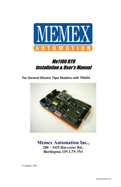
<strong>Mx1100</strong> <strong>BTR</strong><br />
Installation & User’s <strong>Manual</strong><br />
For General Electric Tape Readers with TRAD4<br />
<strong>Memex</strong> <strong>Automation</strong> Inc.,<br />
200 – 3425 Harvester Rd.,<br />
Burlington, ON L7N 3N1<br />
© January 2011<br />
ISO9000\M100710C
ii _ <strong>Mx1100</strong> User’s <strong>Manual</strong>
Table of Contents<br />
Introduction...............................................................................V<br />
About this manual....................................................................... V<br />
Behind the Tape Readers.......................................................... VI<br />
Chapter 1 – Installation Instructions...................................... 1<br />
Component Checklist..................................................................1<br />
Installing the <strong>Mx1100</strong> <strong>BTR</strong>........................................................ 3<br />
Operating Your <strong>BTR</strong>.................................................................. 4<br />
Chapter 2 – Reference.............................................................. 7<br />
General Troubleshooting............................................................ 7<br />
<strong>Memex</strong> Customer Support & Service........................................ 9<br />
Glossary................................................................................... 11<br />
Appendix A: Configuration & Settings................................ 15<br />
Software Configurations........................................................... 15<br />
Parameter Settings.................................................................... 15<br />
Basic <strong>BTR</strong> Cable Configurations..............................................17<br />
RS232 <strong>Serial</strong> Port Data............................................................. 18<br />
Appendix B: ASCII Table...................................................... 19<br />
Contents _ iii
iv _ <strong>Mx1100</strong> User’s <strong>Manual</strong>
Introduction<br />
Thank you <strong>for</strong> your purchase of the <strong>Mx1100</strong> <strong>BTR</strong>. <strong>Memex</strong> puts a<br />
great deal of ef<strong>for</strong>t in the design, manufacture and testing of each<br />
unit we sell. We are confident you will find the <strong>Mx1100</strong> a useful<br />
addition to your shop floor communications system.<br />
About this <strong>Manual</strong><br />
This manual contains the specific steps necessary <strong>for</strong> the<br />
installation of your <strong>Mx1100</strong>, as well as operating procedures and<br />
helpful hints <strong>for</strong> operating the <strong>BTR</strong>. It is divided into two chapters<br />
and includes a table of contents, a glossary and two appendices.<br />
Chapter 1<br />
Chapter 2<br />
Installation Instructions explains how to install your<br />
<strong>Mx1100</strong> <strong>BTR</strong> interface board.<br />
Reference contains a troubleshooting section, and<br />
gives you customer service and technical support<br />
in<strong>for</strong>mation.<br />
Appendix A Contains in<strong>for</strong>mation <strong>for</strong> configuring your <strong>BTR</strong> and<br />
two <strong>Memex</strong> serial cable pin out charts.<br />
Appendix B Contains an ASCII chart <strong>for</strong> your reference.<br />
Introduction _ v
Behind The Tape Reader<br />
A <strong>BTR</strong> or Behind the Tape Reader, as it is commonly called, is an<br />
electronic signal processor designed to emulate the signals of a<br />
paper Tape Reader; thus providing an alternate method of data<br />
entry to an NC or CNC control. That method, namely RS232 serial<br />
communication, is an international standard <strong>for</strong>m of electronic<br />
communication and data input that is certainly faster and much<br />
more reliable than the conventional method of punching tape or<br />
<strong>Manual</strong> Data Input (MDI).<br />
Originally, the only possible way a G-Code operating program<br />
could be entered into a machine tool was through MDI mode,<br />
which allowed the program to be inputted using a keypad at the<br />
control. The MDI process was fine <strong>for</strong> small programs, but it was<br />
time consuming and error prone <strong>for</strong> longer programs. It took time<br />
to setup and to proof the MDI code be<strong>for</strong>e operation could<br />
commence. Machine flexibility was low, since each new program<br />
required time to input. With all the wasted time and lack of<br />
flexibility, it was not very long be<strong>for</strong>e someone invented an<br />
alternate <strong>for</strong>m of control input, the paper Tape Reader.<br />
The paper Tape Reader provided a faster, more reliable <strong>for</strong>m of<br />
data input to the industrial control. However, these Tape Readers<br />
were mechanical in nature, and required regular maintenance and<br />
care to per<strong>for</strong>m properly. Tape Readers allowed data and programs<br />
that were punched out on a paper tape to be read in by the control<br />
at a rate of approximately 300 to 400 characters per second. A few<br />
problems inherent in the Tape Reader were: its limited ability to<br />
accept commands, its mechanical problems, its limited ability to<br />
in<strong>for</strong>m the operator of problems and status, its need to be kept<br />
clean and its need <strong>for</strong> lubrication and other maintenance. It was<br />
commonly suggested that a busy shop keep a spare reader in<br />
inventory in preparation <strong>for</strong> the time when one broke down. In<br />
spite of the costs associated with Tape Readers, the advantages of<br />
speedy input and reusable tapes were welcome.<br />
Un<strong>for</strong>tunately, the process of punching data tapes (whether they be<br />
paper, mylar or metal) was expensive, lengthy and necessitated<br />
storage concerns. Because of the absolute nature of a punched tape,<br />
the process had to be redone <strong>for</strong> every program revision. As well,<br />
proper communication had to be kept up between the programmer<br />
and operator <strong>for</strong> the tape to be accurate and kept up to date. Old<br />
tapes had to be filed or destroyed while the latest version had to be<br />
vi _ <strong>Mx1100</strong> User’s <strong>Manual</strong>
marked as such and stored. Finally, the tape itself had to be<br />
handled with care since it was prone to damage.<br />
Later machine controls had a new mode of operation that allowed<br />
their Tape Reader’s “endless” spool of tape to surmount memory<br />
constraints. Originating on Numerical Controls (NC) that had no<br />
memory, Direct Numeric Control (DNC) allowed execution of a<br />
program as the reader read it. This “drip-feed” method meant that<br />
your program was only limited in size by the length of tape that<br />
you used. This type of operation was very much appreciated later<br />
on with the advent of Computerized Numeric Controls (CNC).<br />
With true onboard memory the CNC had much greater capabilities<br />
and inevitably programs got longer and the need <strong>for</strong> more memory<br />
grew. With control memory being expensive and limited, DNC has<br />
remained the only way some modern manufacturers can operate.<br />
With all this said, Tape Readers are still commonplace on modern<br />
controls today. However, with serial DNC capabilities, many shops<br />
use Tape Readers <strong>for</strong> backup purposes only.<br />
The modern equivalent to a Tape Reader is the <strong>BTR</strong> serial<br />
interface board, which emulates paper Tape Readers. The <strong>Mx1100</strong><br />
is a micro-controller based serial interface board, which allows<br />
serial communications with a machine control <strong>for</strong> the purposes of<br />
loading programs into memory or running DNC. <strong>BTR</strong>’s generally<br />
connect with a computer and permit a programmer to send a<br />
completed, <strong>for</strong>matted program to the machine control. The<br />
machine would then load the program from “Tape” to memory or<br />
to execute the statements, block by block (in the case of DNC).<br />
Since the <strong>Mx1100</strong> <strong>BTR</strong> emulates the Tape Reader, the control<br />
really has no way of knowing that the source of the program is<br />
from a serial port, instead of a paper tape.<br />
The <strong>Mx1100</strong> <strong>BTR</strong> eliminates punching of tape, has no moving<br />
parts, can handle transfer speeds that are 10 times that of a Tape<br />
Reader, uses the programmed (source) file, is less expensive and<br />
does not require maintenance. It’s no wonder that the <strong>BTR</strong>, in<br />
combination with DNC, has become the most cost-effective<br />
alternative to having on-board memory.<br />
Introduction _ vii
While the <strong>Memex</strong> <strong>BTR</strong> gives the modern machine control the<br />
ability to receive programs from a PC, it has nothing to do with<br />
what is being sent to the control. For this, one requires a terminal<br />
program or other serial transfer utility (ie; multi-DNC). Your<br />
control is concerned with the data it receives and the <strong>for</strong>m in which<br />
it is sent. The <strong>BTR</strong> acts only as a gateway or port to your control.<br />
Your terminal program has to be configured to send the data as if it<br />
were a tape. This special program <strong>for</strong>mat is usually described in<br />
your controls Operations <strong>Manual</strong>. Please consult this manual on<br />
how to configure your programs <strong>for</strong> your control. The <strong>BTR</strong> is only<br />
interfacing with the Tape Reader input on your control. Should you<br />
have any additional questions concerning <strong>BTR</strong>’s in general, you<br />
are welcome to call us any time.<br />
viii _ <strong>Mx1100</strong> User’s <strong>Manual</strong>
Chapter 1<br />
Installation Instructions<br />
For General Electric Tape Reader with TRAD4<br />
Estimated time to complete: About 1 hour<br />
Unpacking the <strong>Mx1100</strong><br />
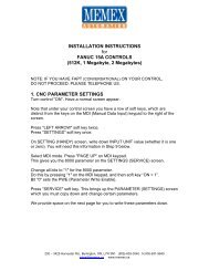
Component Checklist<br />
<br />
<br />
<br />
<br />
<br />
<br />
1 x <strong>Memex</strong> <strong>Mx1100</strong> <strong>BTR</strong>............................ Supplied<br />
1 x Tape Reader interface cable................... Supplied<br />
1 x Connector Board 2A.............................. Supplied<br />
1 x Tape/<strong>BTR</strong> switch................................... Supplied<br />
1 x Power cable............................................ Supplied<br />
1 x <strong>Manual</strong>................................................... Supplied<br />
Optional Components<br />
<br />
<br />
<br />
<strong>Serial</strong> Interface Cable (PC – <strong>BTR</strong>).............. Optional<br />
Facit punch port interface cable.................. Optional<br />
<strong>Serial</strong> Transfer Software (multi-DNC)........ Optional<br />
Be<strong>for</strong>e you Proceed<br />
Please read all instructions be<strong>for</strong>e proceeding. We recommended<br />
that you first make a temporary installation, so that you familiarize<br />
yourself with the components and orientation of the assembly<br />
be<strong>for</strong>e making the installation permanent (ie; routing all cables<br />
through their appropriate channels).<br />
Chapter 1: Installation Instructions _ 1
Installing the <strong>Mx1100</strong> <strong>BTR</strong><br />
General<br />
The <strong>Memex</strong> <strong>BTR</strong> installation is a straight <strong>for</strong>ward, relatively easy to<br />
complete, procedure. All the hardware and accessories are provided <strong>for</strong><br />
you. All you need are some basic skills and hand tools. The installation<br />
requires you to mount the <strong>Memex</strong> <strong>BTR</strong> on the inside of the Tape<br />
Reader door, unplug the Tape Reader and connect the <strong>BTR</strong>. A ribbon<br />
cable that is supplied allows the Reader to be reconnected via the <strong>BTR</strong>.<br />
To install your <strong>Mx1100</strong><br />
1. Prepare the site.<br />
Ensure that the Tape Reader and control are working properly<br />
be<strong>for</strong>e committing to this installation. When you are ready, turn<br />
OFF all power to the control, machine and your computer system.<br />
2. Open the control door.<br />
Locate the door on your machine control that has the Tape Reader<br />
mounted in it. Open this door to gain access to the back of the<br />
Reader.<br />
3. Locate the 20-pin connector.<br />
Locate and identify the TRAD4 amplifier board on the back of the<br />
Tape Reader. On it you will find a 20-conductor cable that goes to<br />
the control. This connector is labeled TRAD4-1PL on the amplifier<br />
board. You can also locate the terminal block labeled TB-1. This is<br />
where you will connect power to the <strong>BTR</strong>.<br />
4. Disconnect the Control.<br />
Disconnect the 20-conductor ribbon cable from the TRAD4 board.<br />
5. Connect to the Control.<br />
Take the 20-conductor from the control and plug it into the <strong>BTR</strong> at<br />
the position labeled “Control A”. The red wire on the cable should<br />
be aligned with pin 1 (marked with a white dot).<br />
6. Mount the <strong>Mx1100</strong> <strong>BTR</strong>.<br />
Locate and magnetically mount your <strong>Memex</strong> <strong>BTR</strong> serial interface<br />
board in a convenient spot on the back of the door. If you wish to<br />
use the <strong>BTR</strong>/Tape mode switch, connect it to SWITCH header on<br />
board and mount to cabinet.<br />
2 _ <strong>Mx1100</strong> User’s <strong>Manual</strong>
7. Connect the Tape Reader.<br />
Connect the 20-conductor cable that was supplied in your kit to the<br />
position labeled “Tape Reader A”. The red wire on the cable<br />
should be aligned with pin 1 (marked with a white dot). The other<br />
end of this cable can be connected to TRAD4-1PL.<br />
8. Option: Facit punch cable.<br />
Locate the punch port on your control. It is a navy-blue, DB25F<br />
connector. Plug the Facit punch cable into this port and plug the<br />
other end (26-pin IDC) into the <strong>BTR</strong> connector labeled “PUNCH<br />
INPUT”. Ensure that you have the proper alignment of pin 1.<br />
9. Mark the Cables.<br />
Mark the connectors and cables so that you are sure that they will<br />
be reassembled properly during the final assembly process.<br />
Disassemble the cables in order to route them neatly with the <strong>BTR</strong><br />
unit attached at a convenient location inside the control cabinet.<br />
10. Connect the Power<br />
Connect the power cable to the terminal labeled TB1, found in<br />
Step 3. Terminal C is the +12VDC supply. Terminal D is the GND<br />
connection. Make sure you have the correct polarity when you<br />
connect this cable to the power block on the <strong>BTR</strong>.<br />
11. Connect to Computer.<br />
Now connect a serial cable from the DB9M (HOST port) on the<br />
<strong>BTR</strong> unit to the computer’s serial port. Route the extra cable in a<br />
neat and tidy fashion and secure with tie-wraps. Refer to page 16<br />
<strong>for</strong> cable diagrams.<br />
12. Clean Up.<br />
Complete the installation by tidying up the cables and making<br />
them neat. Plug in the power cords <strong>for</strong> the computer. Check your<br />
work, and turn on the power. Everything should come to life.<br />
Caution<br />
It is very important that the cables be installed<br />
properly and with the correct orientation. If an end of<br />
one of the Reader cables is plugged in upside down,<br />
sever damage will occur to the Option Card, Tape<br />
Reader and the Control’s Master Board.<br />
Chapter 1: Installation Instructions _ 3
Configure the <strong>BTR</strong>.<br />
Set jumpers A1 through A8 to configure the <strong>BTR</strong> communications<br />
to match your DNC system (see page 19):<br />
A1 and A2 set the Baud rate. Typically 9600 baud (both<br />
jumpers ON) is used unless your cable doesn’t support that<br />
rate reliably. The RS232 specification supports 9600 Baud<br />
with a cable length up to 50 feet (15 metres), but it is often<br />
possible to exceed that. It’s important to use cable specifically<br />
designed <strong>for</strong> RS232 serial data, 22 AWG, twisted pair,<br />
stranded wire (not solid), shielded. Low capacitance (a rating<br />
of 11 to 15 pF per foot) is best. In any case, if you have a long<br />
cable run or are experiencing unreliable data transmission, try<br />
lowering the Baud rate. NOTE: CAT5 Ethernet cable is not<br />
suitable <strong>for</strong> use as serial data cable.<br />
A3 OFF adds hardware (RTS/CTS) handshaking. A3 ON is<br />
software (Xon/Xoff) only. Generally it is preferable to use<br />
both, which means setting A3 OFF and making sure your<br />
cable supports hardware handshaking (see Note 5 on page 10).<br />
A4 OFF uses the standard Xoff character, $13 Hex. Set A4<br />
ON if your DNC or terminal software uses $93 Hex <strong>for</strong> Xoff.<br />
A5 OFF uses the standard Xon/Xoff handshaking method (a<br />
single Xoff). Setting A5 ON sends a continuous stream of<br />
Xoff back to the computer until the next Xon. This enables the<br />
<strong>BTR</strong> to be used with some terminal programs that were<br />
intended <strong>for</strong> use with a modem, such as Procomm although<br />
we highly recommend the use of proper DNC software.<br />
A6 OFF will echo incoming data back to the PC <strong>for</strong> diagnostic<br />
purposes. Set A6 ON <strong>for</strong> normal use.<br />
A7 OFF is ISO data and ON converts incoming data to EIA<br />
<strong>for</strong>mat <strong>for</strong> controls that require EIA data.<br />
A8 overrides the Tape Reader’s selection of <strong>BTR</strong> or Tape<br />
mode. If the Tape Reader wasn’t reconnected to the <strong>BTR</strong>, or if<br />
the Tape Reader isn’t intended to be used often and the <strong>BTR</strong><br />
will usually in Tape mode, set A8 ON. (Remember to remove<br />
it when a tape needs to be read.)<br />
SG JMPR OFF = COM1 Signal Ground surge suppression.<br />
Installation _ 5<br />
Chapter 1: Installation _ 5<br />
4 _ Mx1000 User’s <strong>Manual</strong>
PWR P9 DBL ON activates power output on COM1’s pin 9,<br />
<strong>for</strong> use with devices such as buffers (see note on page 20).<br />
9. Connect to the Computer.<br />
Connect a serial cable from the 9-pin COM1 on the <strong>BTR</strong> to the<br />
computer’s serial port (see page 20 <strong>for</strong> cable configurations).<br />
10. Test the Functionality.<br />
Refer to “Operating the <strong>Mx1100</strong> UMI <strong>BTR</strong>” (page 7), and if<br />
necessary, “Reference” (page 9).<br />
11. Mark and Reroute the Cables.<br />
Mark the connectors and cables to ensure proper reconnection.<br />
Disconnect the cables and route them neatly where they won’t be<br />
pinched, etc. Mount the <strong>BTR</strong> in a safe location inside the control<br />
cabinet. Carefully reattach and secure all cables with cable ties.<br />
6 _ <strong>Mx1100</strong> UMI <strong>BTR</strong> User’s <strong>Manual</strong><br />
Note:<br />
Follow the procedures in your Operators <strong>Manual</strong> with one exception:<br />
Keep the switch on your Tape Reader in the RELEASE position when<br />
you wish to load programs through the <strong>BTR</strong>. The <strong>Mx1100</strong> <strong>BTR</strong> senses<br />
the position of the “AUTO / RELEASE” switch on the Tape Reader.<br />
Your control will load the G-Code file as if it were a tape, although it<br />
will indeed load from your computer through the <strong>BTR</strong>.<br />
Chapter 2: Reference _ 9
Helpful hints<br />
<br />
<br />
Some combinations of DNC software and CNC control<br />
sometimes miss the end of an uploaded file. Adding a couple<br />
of Carriage Returns to the end of the file as a buffer will<br />
ensure that the entire file is transmitted.<br />
The <strong>BTR</strong> responds to the Break character by resetting<br />
and clearing its buffer. The Break character is ASCII<br />
value 3, or HEX 03 (see Appendix B, page 21). If your<br />
DNC software can be configured to send control codes,<br />
it’s a good idea to have it send a Break character at the<br />
beginning of every part program. This will guarantee that<br />
the <strong>BTR</strong> buffer is reset and ready <strong>for</strong> a new program<br />
each time, even if the CNC didn’t properly finish reading<br />
the previous one. (The Break character will not be<br />
passed through to the CNC, and the start of the program<br />
following it will wait while the <strong>BTR</strong> is resetting.)<br />
Operating _ 7<br />
4 _ Mx1000 User’s <strong>Manual</strong>
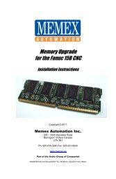
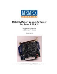
Jumpers A1-A8<br />
COM 1<br />
Connect to<br />
Computer<br />
Reset<br />
Configuration<br />
SP1<br />
Mode Switch<br />
Connector<br />
JP16, +24TR<br />
24 Volt selector<br />
JP22, SG JMPR<br />
Disables Signal<br />
Ground Surge<br />
Suppression on COM1<br />
J7, Power Terminal<br />
JP33, PWR P9 DBL<br />
Enable power output on<br />
COM1 pin 9<br />
JP10, REG ENBL<br />
24 Volt regulator<br />
Cable keyway.<br />
If cable has no key, be extra<br />
careful orienting the cable<br />
MEMEX ETHERNET MODULE<br />
Power<br />
Status<br />
Status LEDs<br />
JP7, CONTROL B<br />
Connect to <strong>Memex</strong> <strong>GE</strong> Adapter<br />
Pin 1 indicator:<br />
Cable's red stripe<br />
always goes on<br />
whichever side has<br />
this mark<br />
JP6, TAPE READER B<br />
Connect to <strong>Memex</strong> <strong>GE</strong> Adapter<br />
1<br />
1<br />
1<br />
JP17<br />
Punch Disable<br />
- Must be ON<br />
<strong>for</strong> <strong>GE</strong> CNC<br />
COM1<br />
A1<br />
A2<br />
A3<br />
A4<br />
A5<br />
A6<br />
A7<br />
A8<br />
RESET<br />
LOAD<br />
+7-24V<br />
+5V<br />
-GND<br />
JP16<br />
+24TR<br />
J7<br />
JP22<br />
SG JMPR<br />
PWR P9 DBL<br />
REG ENBL<br />
JP10<br />
S/N: 030301-<br />
MEMEX ELECTRONICS INC.<br />
(C)2003<br />
PWR ON<br />
STATUS<br />
TX<br />
RX<br />
RTS<br />
CTS<br />
TX<br />
RX<br />
RTS<br />
CTS<br />
COM1 COM2<br />
1<br />
FANUC CONTROL A<br />
CONTROL B<br />
JP8<br />
JP7<br />
TAPE READER B<br />
UNIVERSAL MACHINE INTERFACE<br />
MX1100 R3<br />
MADE IN CANADA<br />
WWW.MEMEX.CA<br />
FANUC TAPE READER A<br />
PUNCH DISABLE<br />
JP17<br />
JP18<br />
+5TR<br />
1<br />
1<br />
1<br />
JP18, +5TR<br />
5 Volt selector<br />
PUNCH IN JP4<br />
TAPE IN JP13<br />
SP1 JP3<br />
IMPORTANT: When powering the <strong>BTR</strong> via<br />
Terminal Block J7, both +24TR and REG ENBL must<br />
be ON and +5TR OFF. (See Step 3 on Page 2.)<br />
1<br />
JP5<br />
JP6<br />
Layout of the <strong>Mx1100</strong> UMI <strong>Serial</strong> <strong>BTR</strong><br />
8 _ <strong>Mx1100</strong> UMI <strong>BTR</strong> User’s <strong>Manual</strong><br />
Chapter 2: Reference _ 7
Reference<br />
Chapter 2<br />
This chapter contains troubleshooting hints and in<strong>for</strong>mation about<br />
<strong>Memex</strong> Technical Support and Service.<br />
General Troubleshooting<br />
The <strong>Mx1100</strong> is designed to install easily and quickly. However, if you<br />
do experience difficulty in the procedures, please check the following<br />
to isolate the problem and resolve it quickly.<br />
1. Check that the Display is on and bright on the <strong>BTR</strong>. It is<br />
located* on the lower edge of the <strong>BTR</strong> left of center.<br />
If there is no power to the <strong>BTR</strong>, ensure that the cables from the<br />
Control and from the Tape Reader are oriented properly and are<br />
well secured.<br />
2. The file you are sending to your control doesn’t wait <strong>for</strong> you to<br />
press “Cycle Start”.<br />
You probably do not have the correct “handshaking” set. Check<br />
that you are using either Hardware or Software handshaking on<br />
your terminal software. Also check that the appropriate option is<br />
set on the <strong>BTR</strong>. If you are using Software handshaking, some<br />
terminal programs look at the XOFF character (13 hex) with even<br />
parity (93 hex). If you are trying to use Hardware handshaking,<br />
make sure that you are using the proper cable. See Appendix A.<br />
Note:<br />
* All references made to objects located on the <strong>BTR</strong> will be<br />
made with respect to the <strong>BTR</strong> being oriented horizontally so that you<br />
can read the <strong>Memex</strong> Electronics name at the top, left of center.<br />
6 _ Mx1000 User’s <strong>Manual</strong>
3. Your control gives you an error after pressing “Cycle Start”.<br />
Try to remove either the CR (carriage return) characters from your<br />
program. Machine controls usually read ISO or EIA code through<br />
a taper reader. As a result they may only accept “pure” ISO or EIA<br />
code through the Tape Reader or <strong>BTR</strong>. These codes typically do<br />
not contain any CR characters so your control may give an error if<br />
it reads one.<br />
4. Your control gives you a Tape Vertical (TV) alarm.<br />
“Tape Vertical” checking was a way that CNC controls verified the<br />
accuracy of the program code they read in through the Tape<br />
Reader. It is usually an option and does not apply when you are<br />
using a <strong>BTR</strong>. Disable this option on your CNC control.<br />
5. Your control gives you a Tape Horizontal (TH) alarm.<br />
Tape Horizontal is equivalent to Even parity. Use even parity when<br />
you are sending your programs from the terminal or PC.<br />
6. Other machine errors:<br />
Ensure that you have added in the proper tape codes at the<br />
beginning or end of your program. Some machines require that you<br />
have a % sign as the first and/or last character in your program.<br />
Check your control manual <strong>for</strong> any termination characters that may<br />
be required.<br />
Chapter 2: Reference _ 9
<strong>Memex</strong><br />
Technical Support & Service<br />
<strong>Memex</strong> <strong>Automation</strong> provides technical support <strong>for</strong> the <strong>Mx1100</strong> <strong>BTR</strong>.<br />
If you have a problem, be sure to review the troubleshooting section of<br />
this manual prior to calling <strong>for</strong> technical support. If you cannot resolve<br />
a problem after reading through the troubleshooting section of this<br />
manual, please contact <strong>Memex</strong> <strong>Automation</strong> technical support at (905)<br />
635-3041<br />
If you have any other questions or concerns, need answers to technical<br />
questions, or need in<strong>for</strong>mation about <strong>Memex</strong> products and/or services<br />
please contact your local product dealer, or contact <strong>Memex</strong> <strong>Automation</strong><br />
sales at the address below:<br />
<strong>Memex</strong> <strong>Automation</strong> Inc.<br />
200 – 3425 Harvester Rd.,<br />
Burlington, ON, L7N 3N1<br />
Canada<br />
Phone: 905-635-1540<br />
Fax: 905-631-9640<br />
Sales: 905-635-3043<br />
Tech support: (905) 635-3041<br />
http://www.memx.ca<br />
Email: sales@memx.ca<br />
support@memx.ca<br />
8 _ <strong>Mx1100</strong> User’s <strong>Manual</strong>
Glossary<br />
ANSI (American National Standards Institute) The official US<br />
agency and voting representative <strong>for</strong> ISO. This institute develops<br />
in<strong>for</strong>mation exchange standards above 50 Mbps.<br />
ASCII (American Standard Code <strong>for</strong> In<strong>for</strong>mational Interchange) A<br />
seven bit alphanumeric code used extensively in data communications.<br />
A parity bit is often added to the seven-bit code <strong>for</strong> error detection.<br />
ASR 33 An asynchronous serial interface standard that specifies the<br />
electrical, functional, and mechanical interface specification between<br />
communicating devices. Also known as “Current Loop”.<br />
ASYNCHRONOUS TRANSMISSION The transmission of<br />
characters separated by time intervals that vary in length, usually in<br />
accordance with the key entries of a terminal operator. Start and stop<br />
bits are used to identify (frame) the beginning and end of the<br />
asynchronously transmitted character.<br />
BAUD RATE The rate at which a signal is changed or modulated.<br />
Baud rate is directly related to the number of bits transmitted per<br />
second.<br />
<strong>BTR</strong> (Behind the Tape Reader) An electronic input device used to<br />
emulate a Tape Readers signals on a machine control. They usually<br />
convert some <strong>for</strong>m of serial communication to the parallel Tape Reader<br />
signals.<br />
CNC (Computerized Numerical Control) An industrial computer that<br />
is used to control the axis and movement of a machine. A CNC usually<br />
uses programs coded with G-codes and M-codes.<br />
CONTROL Refers to a Computerized Numerical Control (CNC).<br />
CTS (Clear To Send) One of the control lines used in RS232<br />
communication. Found on pin 4 or 5 on a DB25 and pin 4 or 8 on a<br />
DB9 depending on the type of device (DTE or DCE).<br />
Glossary _ 11
CURRENT LOOP A serial interface standard that has evolved from<br />
the old electromechanical teletype which used current to activate its<br />
relays. Typically 20ma or 60ma is turned on and off in accordance with<br />
the binary serial data.<br />
DCE (Data Communication Equipment) Typically a modem or data<br />
set used to interface a terminal or computer to the telephone lines.<br />
DNC (Direct/Distributed Numeric Control) A means of communicating<br />
or “Drip Feeding” a program to a CNC through a Tape<br />
Reader or serial interface. The program code is acted upon immediately<br />
block by block as it is read by the control.<br />
DTE (Data Terminal Equipment) In data communications, it is an<br />
end user or termination circuit, typically a terminal or computer.<br />
ECHO A reflected signal. In<strong>for</strong>mation is sent back to the transmitter<br />
from the receiver, often <strong>for</strong> verification purposes.<br />
EIA (Electronic Industries Alliance) A United States organization of<br />
manufacturers that establishes and recommends industrial standards.<br />
They developed the EIA standard code used in early NC and CNC<br />
communications.<br />
FRAMING The procedure used to identify the beginning and end of a<br />
group of data bits.<br />
FRAMMING ERROR This type of error occurs when a receiver<br />
looses synchronism to the incoming data.<br />
HANDSHAKING A process that regulates and controls the flow of<br />
data between two devices.<br />
HARDWARE HANDSHAKING Handshaking by use of the RTS<br />
and CTS control lines on a RS232 serial interface.<br />
ISO (International Standards Organization) One of the largest and<br />
most widely recognized standards organizations in the world. Also, a<br />
<strong>for</strong>m of data encryption similar to ASCII. It is a <strong>for</strong>m of 7 bit ASCII<br />
with even parity used largely on CNC’s.<br />
LOCAL ECHO When a terminal is configured to internally route its<br />
transmitted character around to its receiver section <strong>for</strong> display, a local<br />
echo is said to be generated.<br />
12 _ <strong>Mx1100</strong> User’s <strong>Manual</strong>
MARK A logic 1.<br />
MODEM A contraction of the words modulator/demodulator. The<br />
modem converts a computer’s digital bit stream into an analog signal<br />
suitable <strong>for</strong> the telephone lines and vice versa.<br />
PAPER TAPE A media of program code storage. Holes were<br />
punched in the paper tape to represent different program codes. These<br />
tapes were then read through a Tape Reader to be loaded into CNC<br />
memory.<br />
PARITY An error detection method whereby a single bit is added to a<br />
group of bits to make the total number of 1 bits either even or odd<br />
(depending on the type of parity; even or odd).<br />
PARITY ERROR Indicates that the total number of 1 bits in a<br />
received character does not agree with the type of parity expected.<br />
RI (Ring Indicator) One of the control lines used by modems in<br />
RS232 communication. Found on pin 18 on a DB25 and pin 9 on a<br />
DB9 connector.<br />
RS232-C An asynchronous serial interface standard that specifies the<br />
electrical, functional, and mechanical interface specification between<br />
data communication devices.<br />
RTS (Request To Send) One of the control lines used in RS232<br />
communication. Found on pin 4 or 5 on a DB25 and pin 4 or 8 on a<br />
DB9 connector (depends on whether port is <strong>for</strong> DCE or DTE).<br />
RTS/CTS Hardware handshaking using the RTS and CTS control<br />
lines.<br />
Rx Receive Data<br />
SG Signal Ground.<br />
START BIT The first bit used to frame an asynchronously transmitted<br />
character. Its logic level is a 0 (space).<br />
STOP BIT The last bit used to frame an asynchronously transmitted<br />
character. Its logic level is a 1 (mark).<br />
Glossary _ 13
SYNCHRONOUS TRANSMISSION High speed communication<br />
whereby data characters are sent in direct succession to each other<br />
without the use of Start and Stop bits.<br />
TAPE READER Input device used on CNC Machines and other<br />
industrial equipment. Used to “read” coded data on a punched paper<br />
tape. Older Tape Readers were a mechanical device; today Tape<br />
Readers use optical devices that sense light passing through the holes in<br />
the tape.<br />
TERMINAL An input/output device used by an operator to communicate<br />
with a host computer. It consists of a keyboard and a display to<br />
monitor alphanumeric characters entered at the keyboard or received<br />
from a remote device.<br />
TIME-OUT ERROR This type of error occurs when a device fails to<br />
respond to a message within a given period of time.<br />
TTY Teletype Used in the Telex exchange. An electromechanical<br />
terminal consisting of a keyboard, printer, paper Tape Reader and<br />
punch. Teletype is a trade mark of the <strong>for</strong>mer Teletype Corp.<br />
Tx Transmit Data.<br />
XOFF (Transmit Off) A device control character (DC3 or $13 hex)<br />
used to control the flow of data between two devices. XOFF is used as<br />
a handshake with XON.<br />
XON (Transmit On) A device control character (DC1 or $11 hex)<br />
used to control the flow of data between two devices. XON is used as a<br />
handshake with XOFF.<br />
XON/XOFF Software handshaking using the XON and XOFF control<br />
characters.<br />
14 _ <strong>Mx1100</strong> User’s <strong>Manual</strong>
Appendix A<br />
Configurations & Settings<br />
Software Configurations<br />
Baud................................ 9600<br />
Parity................................Even<br />
Data Bits......................... 7<br />
Stop Bits.......................... 1<br />
ASCII Xfer Options.......... With Strip the High Bit – ON<br />
Duplex............................. FULL<br />
Handshake...................... OFF<br />
Parameter Settings on <strong>BTR</strong><br />
Mode 0: Run Mode<br />
Value Run Modes LED Display<br />
0 Auto A-btr...A-tAPE<br />
1 <strong>BTR</strong> Btr<br />
2 Tape TAPE<br />
3 S-<strong>BTR</strong> S-btr<br />
4 S-Tape S-tAPE<br />
A Save RAM to Flash 12345 12345 done<br />
B <strong>Serial</strong> Setup SEt UP 1<br />
C <strong>BTR</strong> Setup SEt UP 2<br />
D<br />
Diagnostic Mode<br />
E<br />
PTR Analyzer<br />
F Loader (figure 8)<br />
Mode 1: Host Port Baud Rate (to PC or DNC system)<br />
0 1 2 3 4 5 6 7 8 9<br />
9600 150 300 600 1200 2400 4800 9600 19200 115.2<br />
Mode 2: Host Port Character Frame<br />
Value Parity Data Bits Stop Bits<br />
0 Even 7 1<br />
1 Even 7 2<br />
2 Even 8 1<br />
3 Even 8 2<br />
4 None 7 1<br />
5 None 7 2<br />
6 None 8 1<br />
7 None 8 2<br />
8 Odd 7 1<br />
9 Odd 7 2<br />
A Odd 8 1<br />
B Odd 8 2<br />
Appendix A: Configurations & Settings _ 15
Mode 3: Host Port Flow Control<br />
0 1 2 3<br />
None Hardware Software Hard & Soft<br />
Mode 4: Data Mode<br />
0 1 2<br />
ISO EIA Transparent<br />
Mode 5: Configuration<br />
Value Xoff Char<br />
(hex)<br />
Continuous<br />
Xoff<br />
Echo Punch<br />
Disable<br />
0 13 Yes Yes Yes<br />
1 93 Yes Yes Yes<br />
2 13 No Yes Yes<br />
3 93 No Yes Yes<br />
4 13 Yes No Yes<br />
5 93 Yes No Yes<br />
6 13 No No Yes<br />
7 93 No No Yes<br />
8 13 Yes Yes No<br />
9 93 Yes Yes No<br />
A 13 No Yes No<br />
B 93 No Yes No<br />
C 13 Yes No No<br />
D 93 Yes No No<br />
E 13 No No No<br />
F 93 No No No<br />
Mode 6: Memory Mode<br />
0 1 2 3 4<br />
Run DNC Run from<br />
RAM Memory<br />
Loop RAM<br />
Memory<br />
Run from<br />
Flash<br />
Loop Flash<br />
Mode 7: Tape Reader Model Types<br />
0 1 2 3 4 5<br />
Fanuc Sanyo Remex <strong>GE</strong> EECO TRAD4<br />
Mode 8: Tape Reader Speed (C.P.S.)<br />
0 1 2 3 4 5 6 7<br />
300 150 200 250 300 350 400 450<br />
Mode 9: Host Port Functionality<br />
0 1 2 3 4<br />
Terminal SMT Punch Tape<br />
Mode A: Aux. Port Baud Rate<br />
0 1 2 3 4 5 6 7 8 9<br />
9600 150 300 600 1200 2400 4800 9600 19200 115.2<br />
16 _ <strong>Mx1100</strong> User’s <strong>Manual</strong>
Mode B: Aux. Port Character Frame<br />
Value Parity Data Bits Stop Bits<br />
0 Even 7 1<br />
1 Even 7 2<br />
2 Even 8 1<br />
3 Even 8 2<br />
4 None 7 1<br />
5 None 7 2<br />
6 None 8 1<br />
7 None 8 2<br />
8 Odd 7 1<br />
9 Odd 7 2<br />
A Odd 8 1<br />
B Odd 8 2<br />
Mode C: Aux. Port Flow Control<br />
0 1 2 3<br />
None Hardware Software Hard & Soft<br />
Basic <strong>BTR</strong> Cable Configurations<br />
A – Software Handshaking Only<br />
Computer<br />
DB-25F<br />
<strong>Mx1100</strong> <strong>BTR</strong><br />
DB-9F<br />
2 2<br />
3 3<br />
7 7<br />
DB-9F<br />
DB-9F<br />
3 2<br />
2 3<br />
5 5<br />
B - Hardware Handshaking<br />
Computer<br />
DB-25F<br />
<strong>Mx1100</strong> <strong>BTR</strong><br />
DB-9F<br />
2 2<br />
3 3<br />
4 8<br />
5 7<br />
7 5<br />
DB-9F<br />
DB-9F<br />
3 2<br />
2 3<br />
7 8<br />
8 7<br />
5 5<br />
Appendix A: Configurations & Settings _ 17
RS232 <strong>Serial</strong> Port Data (both DB9F)<br />
Pin 1.....................................................................................NC<br />
Pin 2.....................................................................Receive Data<br />
Pin 3....................................................................Transmit Data<br />
Pin 4....................................................................................DTE<br />
Pin 5....................................................................Signal Ground<br />
Pin 6......................................................................................NC<br />
Pin 7....................................................................................RTS<br />
Pin 8....................................................................................CTS<br />
Pin 9.....................................................................................NC<br />
How To Reload New Firmware<br />
The <strong>Mx1100</strong> firmware filename will be <strong>BTR</strong>2.E19.<br />
1. Connect your computer to the AUX port on the <strong>BTR</strong>.<br />
2. Setup a terminal on your computer <strong>for</strong> 19200, N, 8, 1.<br />
3. Enter the loader on the <strong>BTR</strong> by setting the MODE switch to 'F' as<br />
well as the VALUE switch to 'F' and then press the ENTER button.<br />
The LED should be displaying a "figure 8" pattern. Press <br />
a couple of times on your terminal. You should now see “>”.<br />
4. Type "LS" then to "Load S-Record" and then send the<br />
<strong>BTR</strong>2.E19 file using an ASCII transfer. The following is an<br />
example of what you should see (CSUM and CRC may differ):<br />
Send S-Records... to abort.<br />
00.00.26 ES[55FE]<br />
Erasing sector 1...[OK]<br />
Programming 65536 bytes...[OK]<br />
Calculating application CRC...[55FE]<br />
Calculating application CSUM...[871854CE]<br />
5. Once you see the prompt again (as shown above), you can set the<br />
Mode switch to 0, the Value switch back to 1 or 2 <strong>for</strong> <strong>BTR</strong> mode<br />
or Tape mode, the type “QU” and at the prompt. The<br />
<strong>Mx1100</strong> is now reprogrammed.<br />
18 _ Mx1000 User’s <strong>Manual</strong>
Appendix B<br />
ASCII Table<br />
DEC HEX SYM KEY DEC HEX SYM DEC HEX SYM<br />
0 0 NUL ctrl @ 43 2B + 86 56 V<br />
1 1 SOH ctrl A 44 2C , 87 57 W<br />
2 2 STX ctrl B 45 2D - 88 58 X<br />
3 3 ETX ctrl C 46 2E . 89 59 Y<br />
4 4 EOT ctrl D 47 2F / 90 5A Z<br />
5 5 ENQ ctrl E 48 30 0 91 5B [<br />
6 6 ACK ctrl F 49 31 1 92 5C \<br />
7 7 BEL ctrl G 50 32 2 93 5D ]<br />
8 8 BS ctrl H 51 33 3 94 5E ^<br />
9 9 HT ctrl I 52 34 4 95 5F _<br />
10 A LF ctrl J 53 35 5 96 60 `<br />
11 B VT ctrl K 54 36 6 97 61 a<br />
12 C FF ctrl L 55 37 7 98 62 b<br />
13 D CR ctrl M 56 38 8 99 63 c<br />
14 E SO ctrl N 57 39 9 100 64 d<br />
15 F SI ctrl O 58 3A : 101 65 e<br />
16 10 DLE ctrl P 59 3B ; 102 66 f<br />
17 11 DC1 ctrl Q 60 3C < 103 67 g<br />
18 12 DC2 ctrl R 61 3D = 104 68 h<br />
19 13 DC3 ctrl S 62 3E > 105 69 i<br />
20 14 DC4 ctrl T 63 3F 106 6A j<br />
21 15 NAK ctrl U 64 40 @ 107 6B k<br />
22 16 SYN ctrl V 65 41 A 108 6C l<br />
23 17 ETB ctrl W 66 42 B 109 6D m<br />
24 18 CAN ctrl X 67 43 C 110 6E n<br />
25 19 EM ctrl Y 68 44 D 111 6F o<br />
26 1A SUB ctrl Z 69 45 E 112 70 p<br />
27 1B ESC ctrl [ 70 46 F 113 71 q<br />
28 1C FS ctrl \ 71 47 G 114 72 r<br />
29 1D GS ctrl ] 72 48 H 115 73 s<br />
30 1E RS ctrl ^ 73 49 I 116 74 t<br />
31 1F US ctrl _ 74 4A J 117 75 u<br />
32 20 SP 75 4B K 118 76 v<br />
33 21 ! 76 4C L 119 77 w<br />
34 22 “ 77 4D M 120 78 x<br />
35 23 # 78 4E N 121 79 y<br />
36 24 $ 79 4F O 122 7A z<br />
37 25 % 80 50 P 123 7B {<br />
38 26 & 81 51 Q 124 7C |<br />
39 27 ‘ 82 52 R 125 7D }<br />
40 28 ( 83 53 S 126 7E ~<br />
41 29 ) 84 54 T 127 7F DEL<br />
42 2A * 85 55 U<br />
Appendix B: ASCII Table _ 19
<strong>Memex</strong> <strong>Automation</strong> Inc.<br />
200 – 3425 Harvester Rd.,<br />
Burlington, ON L7N 3N1<br />
Canada<br />
Phone: 905-635-1540 Fax: 905-631-9640<br />
www.memex.ca<br />
Support – (905) 635-3041<br />
support@memex.ca<br />
Sales – (905) 635-3043<br />
sales@memex.ca<br />
Thank you <strong>for</strong> choosing <strong>Memex</strong> <strong>for</strong> your<br />
Manufacturing Connectivity Solutions<br />
ISO9000\DOCs\Current <strong>Manual</strong>s\M100710C – <strong>Mx1100</strong> <strong>BTR</strong> – <strong>GE</strong> Trad4.doc<br />
18 _ Mx1000 User’s <strong>Manual</strong>