Installation & Operation Manual - Phase-A-Matic, Inc.
Installation & Operation Manual - Phase-A-Matic, Inc.
Installation & Operation Manual - Phase-A-Matic, Inc.

You also want an ePaper? Increase the reach of your titles
YUMPU automatically turns print PDFs into web optimized ePapers that Google loves.
Indoor Location Continued<br />
4. Keep all fuel and its associated piping away from all components of the engine exhaust<br />
system.<br />
5. The exhaust system should be inspected on a regular basis to assure there are no<br />
toxic exhaust gas leaks. In some areas this inspection may be provided by your local<br />
public service.<br />
6. A carbon monoxide tester may be installed to detect the presence of the deadly gas<br />
during times when you are in the building with the engine running (during testing or<br />
maintenance).<br />
<strong>Installation</strong> The generator is completely assembled, tested and adjusted at the factory before it is shipped to<br />
you. The procedures presented in this manual are suggestions and it is the responsibility of the<br />
Owner/Operator to arrange for these procedures to be performed by licensed contractors<br />
according to all applicable codes including local codes for your Municipality/City/County and<br />
State. <strong>Installation</strong> generally includes the following:<br />
1. Secure Generator to concrete pad.<br />
2. Connect Fuel Supply.<br />
3. Electrical Connections − power wiring (optional transfer switch) and control wiring.<br />
4. Battery (not included).<br />
5. Ground Connection.<br />
After installation, the post installation checks must be performed prior to starting the engine.<br />
After these checks have been performed and the system operation is verified to be good, refer to<br />
Section 6 Maintenance for periodic checks that must be performed at scheduled intervals to<br />
ensure continued operation with minimal problems.<br />
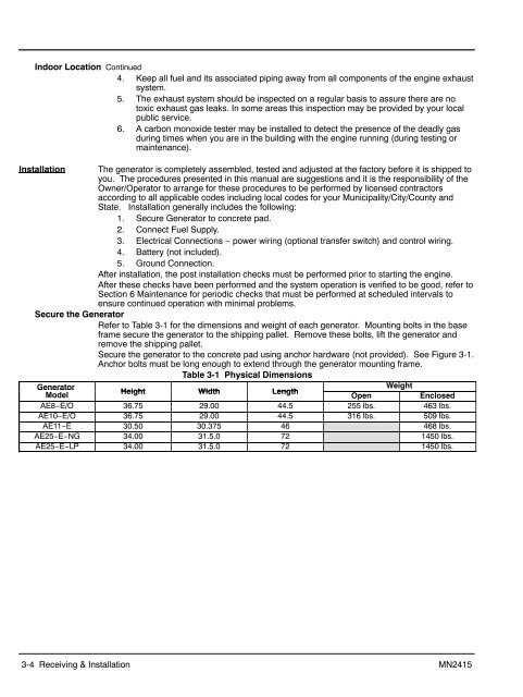
Secure the Generator<br />
Refer to Table 3-1 for the dimensions and weight of each generator. Mounting bolts in the base<br />
frame secure the generator to the shipping pallet. Remove these bolts, lift the generator and<br />
remove the shipping pallet.<br />
Secure the generator to the concrete pad using anchor hardware (not provided). See Figure 3-1.<br />
Anchor bolts must be long enough to extend through the generator mounting frame.<br />
Table 3-1 Physical Dimensions<br />
Generator<br />
Weight<br />
Model<br />
Height Width Length<br />
Open<br />
Enclosed<br />
AE8−E/O 36.75 29.00 44.5 255 lbs. 463 lbs.<br />
AE10−E/O 36.75 29.00 44.5 316 lbs. 509 lbs.<br />
AE11−E 30.50 30.375 46 468 lbs.<br />
AE25−E−NG 34.00 31.5.0 72 1450 lbs.<br />
AE25−E−LP 34.00 31.5.0 72 1450 lbs.<br />
3-4 Receiving & <strong>Installation</strong> MN2415