Installation & Operation Manual - Phase-A-Matic, Inc.
Installation & Operation Manual - Phase-A-Matic, Inc.
Installation & Operation Manual - Phase-A-Matic, Inc.

You also want an ePaper? Increase the reach of your titles
YUMPU automatically turns print PDFs into web optimized ePapers that Google loves.
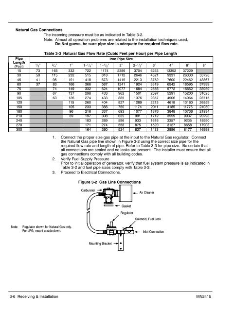
Natural Gas Connections<br />
The incoming pressure must be as indicated in Table 3-2.<br />
Note: Almost all operation problems are related to the installation techniques used.<br />
Do Not guess, be sure pipe size is adequate for required flow rate.<br />
Table 3-3 Natural Gas Flow Rate (Cubic Feet per Hour) per Pipe Length<br />
Pipe<br />
Iron Pipe Size<br />
Length<br />
(Feet)<br />
1 / 2 ″ 3 / 4 ″ 1″ 1− 1 / 4 ″ 1− 1 / 2 ″ 2″ 2− 1 / 2 ″ 3″ 4″ 6″ 8″<br />
15 73 165 332 722 1174 2386 3704 6253 13352 37229<br />
30 50 115 232 515 818 1712 2646 4521 9331 26330 53728<br />
45 41 95 191 418 673 1419 2213 3752 7600 22462 43867<br />
60 37 83 166 366 587 1241 1924 3319 6542 18595 37999<br />
75 74 149 332 524 1077 1684 2886 5772 16652 33959<br />
90 67 137 298 433 962 1501 2597 5291 15200 31025<br />
105 63 126 274 433 885 1376 2357 4906 14064 28715<br />
120 115 260 404 827 1289 2213 4618 13160 26859<br />
150 105 233 366 750 1174 2011 4185 11775 24050<br />
180 96 216 337 693 1077 1876 3848 10736 21934<br />
210 89 197 308 635 991 1712 3559 9937 20298<br />
240 183 289 596 933 1616 3357 9235 18990<br />
270 171 274 558 875 1520 3127 8658 17903<br />
300 164 260 524 827 1433 2886 8177 16998<br />
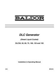
1. Connect the proper size gas pipe at the input to the Natural Gas regulator. Connect<br />
the Natural Gas pipe line shown in Figure 3-2 using the correct size pipe for the<br />
required flow rate and length of pipe. Refer to Table 3-3 for pipe size. Be certain that<br />
all connections are sealed and no leaks are present. The installer must ensure that all<br />
gas connections comply with all building codes.<br />
2. Verify Fuel Supply Pressure<br />
Prior to initial operation of generator, verify that fuel system pressure is as indicated in<br />
Table 3-2 and fuel pipe sizes comply with Table 3-3.<br />
3. Proceed to Electrical Connections.<br />
Figure 3-2 Gas Line Connections<br />
Carburetor<br />
Air Cleaner<br />
Gasket<br />
Regulator<br />
Solenoid, Fuel Lock<br />
Note:<br />
Regulator shown for Natural Gas only.<br />
For LPG, mount upside down.<br />
Inlet Connection<br />
Mounting Bracket<br />
3-6 Receiving & <strong>Installation</strong> MN2415