Installation & Operation Manual - Phase-A-Matic, Inc.
Installation & Operation Manual - Phase-A-Matic, Inc.
Installation & Operation Manual - Phase-A-Matic, Inc.

Create successful ePaper yourself
Turn your PDF publications into a flip-book with our unique Google optimized e-Paper software.
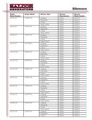
Table C-1 Generator Set Parts List<br />
Ref No. Part No. Description<br />
Not Shown EH0491A02 Enclosure, Top<br />
Not Shown EH0491A11 Enclosure, Access Panel<br />
Not Shown EH0491A01 Enclosure, Front<br />
Not Shown EH0491A10 Enclosure, Right Side (Hinge) & Rear<br />
Not Shown EH0491A13 Enclosure, Left Side (Latch) & Front<br />
Not Shown HB2414A05 Latch<br />
Not Shown HW2409A21 Hinge, Nylon<br />
Not Shown HW2409A22 Hinge, Nylon<br />
Not Shown HW2410A02 Gas Spring, 30 lb.<br />
Not Shown EH0309A02 Control Box<br />
Not Shown EM0046A00 Engine Controller, 4110 Auto Start<br />
Not Shown RE5031A01 Relay<br />
Not Shown EM0027A01 Voltage Regulator (AVC63−20.)<br />
Not Shown CK0070A29 Circuit Breaker 50Amp<br />
Not Shown FU066A02 Fuse, AGC1<br />
Not Shown FU066A00 Fuse, MTH−5<br />
Not Shown SE0057A02 Solenoid, Engine Starting 12V<br />
Not Shown EA5038A00 Muffler<br />
Not Shown HB6116A00 Battery Tie Down<br />
Not Shown HA3187A12 Battery Tie Down Bolt<br />
Not Shown EA0010A04 Battery Charger, 12V, 2AMP<br />
Not Shown EA0000A00 Regulator, K−N, <strong>Manual</strong> Prime<br />
Not Shown SE0071A00 Solenoid, Automatic Gas Valve<br />
Continued<br />
Conversion from LPG to Natural Gas Optional Procedure<br />
If this is a new installation, begin with step 5.<br />
If the generator has been installed, ensure that the following steps are performed:<br />
1. Place the controller in the OFF position.<br />
2. Place the circuit breaker in the OPEN position.<br />
3. Turn off the LPG supply.<br />
Disconnect and remove the LPG equipment and hoses.<br />
4. Disconnect the negative terminal from the starting battery.<br />
Figure C-4<br />
90° Elbow<br />
K−N Regulator<br />
Insert<br />
5. Open the lid and remove the front panel by removing the two 7/16” bolts along the top<br />
edge of the front panel.<br />
6. Remove the hose that connects to the 90° elbow at the top of the demand (K−N)<br />
regulator, Figure C-4.<br />
MN2415<br />
Series AE11 C-3