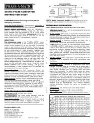
Installation & Operation Manual - Phase-A-Matic, Inc.
Installation & Operation Manual - Phase-A-Matic, Inc.
Installation & Operation Manual - Phase-A-Matic, Inc.

Create successful ePaper yourself
Turn your PDF publications into a flip-book with our unique Google optimized e-Paper software.
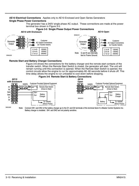
AE10 Electrical Connections Applies only to AE10 Enclosed and Open Series Generators<br />
Single <strong>Phase</strong> Power Connections<br />
The generator has a 240V single phase AC output. These connections are made at the power<br />
terminal box shown in Figure 3-5.<br />
Figure 3-5 Single <strong>Phase</strong> Output Power Connections<br />
AE10 with Enclosure<br />
AE10 Open<br />
BW0201D<br />
Generator<br />
Output<br />
BW0333D<br />
1<br />
N<br />
4<br />
L1<br />
N<br />
L2<br />
L1 to N<br />
L2 to N<br />
L1 to L2<br />
Customer<br />
AC Output Connections<br />
(to Transfer Switch)<br />
120VAC<br />
120VAC<br />
240VAC<br />
Note:<br />
Generator<br />
Output<br />
To Frame<br />
1<br />
N<br />
4<br />
G<br />
G and N are internally<br />
tied to Frame Ground.<br />
L1<br />
N<br />
L2<br />
L1 to N<br />
L2 to N<br />
L1 to L2<br />
Customer<br />
AC Output Connections<br />
(to Transfer Switch)<br />
120VAC<br />
120VAC<br />
240VAC<br />
Remote Start and Battery Charger Connections<br />
Figure 3-6 shows the connections for the battery charger and the remote start contacts of the<br />
transfer switch. When the Remote Start Switch is closed, the generator will start. The unit will<br />
remain running until this connection is opened. When the Remote Start Switch is opened, the<br />
control circuits allow the engine to run for approximately 60−90 seconds before it shuts off. This<br />
time delay allows the engine to run unloaded to cool down before stopping.<br />
Figure 3-6 Remote Start & Battery Connections<br />
AE10<br />
AE10<br />
with Enclosure<br />
Open<br />
16AWG Customer Provided Optional Equipment<br />
16AWG Customer Provided Optional Equipment<br />
R1<br />
R2<br />
Batt+<br />
Batt−<br />
D1<br />
D2<br />
Twisted Pair Wire<br />
Out+<br />
Out−<br />
Remote Start Switch<br />
(Close to Start)<br />
Battery<br />
Charger<br />
To 120VAC<br />
(Shore Power)<br />
BW0201D<br />
Twisted Pair Wire<br />
+ −<br />
Battery<br />
Remote Start Switch<br />
(Close to Start)<br />
Out+<br />
Out−<br />
Battery<br />
Charger<br />
To 120VAC<br />
(Shore Power)<br />
BW0333D<br />
Note:<br />
Connect DK1 and DK2 of the battery charger go to the D1 and D2 terminals of the terminal block if a Master Control Systems <strong>Inc</strong>.<br />
Battery charger is installed. DK1 and DK2 are not polarity sensitive.<br />
3-10 Receiving & <strong>Installation</strong> MN2415