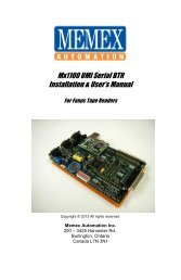
Mx1100 Serial BTR for Sanyo Manual - Memex Automation
Mx1100 Serial BTR for Sanyo Manual - Memex Automation
Mx1100 Serial BTR for Sanyo Manual - Memex Automation

Create successful ePaper yourself
Turn your PDF publications into a flip-book with our unique Google optimized e-Paper software.
Page | 8<br />
Installing the <strong>Mx1100</strong> UMI <strong>BTR</strong><br />
General<br />
The <strong>Memex</strong> <strong>Mx1100</strong> UMI <strong>BTR</strong> installation procedure is straight<strong>for</strong>ward and relatively<br />
easy to complete – connect the <strong>BTR</strong> to the CNC where the Tape Reader was connected,<br />
optionally connect the Tape Reader to the <strong>BTR</strong>, and mount the <strong>BTR</strong> on the inside of the<br />
Tape Reader door. All the hardware and accessories are provided. All that’s needed are<br />
some basic skills and hand tools. Estimated time required: 45 minutes.<br />
1. Prepare the site.<br />
Ensure that the Tape Reader and control are working properly be<strong>for</strong>e beginning the<br />
installation. When ready, turn OFF all power to the control, machine and computer<br />
system.<br />
2. Access the Tape Reader.<br />
Locate the panel on the control that has the Tape Reader mounted on it. Open this<br />
door to gain access to the back of the Reader.<br />
3. Disconnect the Tape Reader.<br />
Locate the 40-pin cable connector labelled J0. It can be found on the circuit board<br />
labelled A7-1-200 on the back of the Tape Reader. A 40-conductor ribbon cable<br />
connects this connector to the CNC. Note which side of this connector the cable’s red<br />
stripe goes on. Disconnect this cable from J0.<br />
4. Connect the <strong>BTR</strong>.<br />
Connect the cable disconnected in Step 3 to the <strong>BTR</strong>’s 40-pin JP7 connector near top<br />
right* (labelled “CONTROL B”), without twisting the cable. Make sure the cable’s<br />
red stripe is on the right, where Pin 1 is marked with a white square (see diagram,<br />
page 7). This connects the <strong>BTR</strong>’s <strong>Sanyo</strong> control port to the control.<br />
Caution<br />
It is very important that the cables are installed properly and with the correct<br />
orientation. If one of the cables is plugged in upside down, severe damage will<br />
occur to the <strong>BTR</strong>, to the Tape Reader and to the control’s Master Board.