Remeha Avanta Plus
Remeha Avanta Plus
Remeha Avanta Plus

Create successful ePaper yourself
Turn your PDF publications into a flip-book with our unique Google optimized e-Paper software.
<strong>Remeha</strong> <strong>Avanta</strong> <strong>Plus</strong><br />
2.7.1 On/off control – room temperature (volt free<br />
switching)<br />
Exist<br />
links<br />
Terminal<br />
Block X9<br />
1<br />
2<br />
3<br />
4<br />
5<br />
6<br />
7<br />
8<br />
X9<br />
Modulating - using Open Therm control<br />
eg: Honeywell Chronotherm or Celcia 20<br />
On / Off - using simple volt free switching control<br />
The <strong>Remeha</strong> <strong>Avanta</strong> <strong>Plus</strong> can be connected to a 2-wire on/<br />
off volt free heating control, programmer or thermostat, ie<br />
<strong>Remeha</strong> Celcia 10. Mount the thermostat in a reference room<br />
usually the living room.<br />
• Remove existing link between connectors 7 and 8 of the X9<br />
terminal block before use;<br />
• Connect the 2-wire programmer or room thermostat to<br />
connectors 7 and 8 of the X9 terminal block.<br />
<br />
If a room thermostat with an anticipation resistor is being used,<br />
parameter p5 should be changed from 0 to 1, see par.<br />
2.9.8.<br />
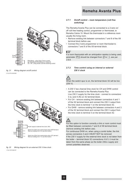
fi g. 21<br />
Wiring diagram on/off control<br />
2.7.2 Time control using an internal or external<br />
230 V clock<br />
LT.AL.W7H.000.026c<br />
<br />
When the switch spur is on, the terminal block X2 will be live<br />
(230 V).<br />
X2<br />
• A 230 V two channel time clock for CH and DHW control<br />
can be connected to the <strong>Remeha</strong> <strong>Avanta</strong> <strong>Plus</strong> .<br />
Live 230 V supply for the time clock - connect to connectors<br />
4 (L) and 5 (N) on X2 terminal block.<br />
• For CH - remove existing link between connectors 4 and 1<br />
of the X2 terminal block and connect the 230 V output from<br />
the time clock to terminal 1 on the terminal block X2.<br />
• For DHW - remove existing link between connectors 4 and 3<br />
of the X2 terminal block and connect the 230 V output from<br />
the time clock to terminal 3 on the terminal block X2.<br />
fi g. 22<br />
Exist<br />
links<br />
Terminal<br />
Block X2<br />
5<br />
4<br />
3<br />
2<br />
1<br />
N<br />
L<br />
Power supply to external time clock -230v<br />
Switch live (230v) from external time clock DHW demand<br />
Remove existing link 4-3 to use this function<br />
Switch live (230v) from external time clock HTG demand<br />
Remove existing link 4-1 to use this function<br />
Wiring diagram for an external 230 V time clock<br />
<br />
For this option to function correctly a link or room control must<br />
be fitted between connectors 7 and 8 of X9 terminal block<br />
(remove existing link before use).<br />
For continuous DHW on, when using a combi boiler, the link<br />
across connectors 3 and 4 MUST NOT be removed<br />
If the 230 V supply for the external time clock is not taken from<br />
the boiler – terminal block X2 connections 4 & 5, it must be<br />
taken from the same phase as the boiler 230cv supply and<br />
correct polarities observed.<br />
LT.AL.W7H.000.027<br />
22