

mdp control series - Omega Engineering
mdp control series - Omega Engineering
mdp control series - Omega Engineering

You also want an ePaper? Increase the reach of your titles
YUMPU automatically turns print PDFs into web optimized ePapers that Google loves.
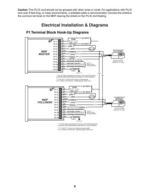
Caution: The PU-E cord should not be grouped with other wires or cords. For applications with PU-E<br />
wire over 6 feet long, or noisy environments, a shielded cable is recommended. Connect the shield to<br />
the common terminal on the MDP, leaving the shield on the PU-E end fl oating.<br />
Electrical Installation & Diagrams<br />
P1 Terminal Block Hook-Up Diagrams<br />
MDP<br />
MASTER<br />
MDP<br />
FOLLOWER<br />
P1-1<br />
P1-2<br />
N<br />
L<br />
FUSE<br />
MD10P = 7.5 Amp*<br />
MD3P = 15 Amp*<br />
AC INPUT<br />
}85-265VAC<br />
AC INPUT<br />
P1-3<br />
-A<br />
-ARM<br />
P1-4<br />
+A<br />
+ARM<br />
MOTOR<br />
P1-5<br />
COM<br />
COMMON black<br />
P1-6<br />
+5V<br />
+5VDC red<br />
P1-7<br />
S1<br />
SIGNAL white<br />
P1-8<br />
S2<br />
**Jog Input<br />
P1-9<br />
P1-10<br />
P1-11<br />
NO<br />
C<br />
NC<br />
Alarm Output - Normally Open<br />
Alarm Output - Common<br />
Form C<br />
Relay Output<br />
Alarm Output - Normally Closed}<br />
(Programmable)<br />
P1-12<br />
IN1<br />
User Input 1<br />
**INHIBIT<br />
COM (P1-5)<br />
black<br />
* For AC inputs utilizing two hot lines, both inputs should be<br />
protected with appropriately sized fuses or circuit breakers.<br />
** P1-8 & P1-12 user input may be programmed<br />
for a number of functions. Including (jog, inhibit, etc.)<br />
white<br />
P1-1<br />
P1-2<br />
P1-3<br />
P1-4<br />
P1-5<br />
P1-6<br />
P1-7<br />
P1-8<br />
P1-9<br />
P1-10<br />
P1-11<br />
P1-12<br />
N<br />
L<br />
FUSE<br />
MD10P = 7.5 Amp*<br />
MD3P = 15 Amp*<br />
AC INPUT<br />
}85-265VAC<br />
AC INPUT<br />
-A<br />
-ARM<br />
+A<br />
+ARM<br />
MOTOR<br />
COM<br />
COMMON<br />
black<br />
+5V<br />
+5VDC<br />
red<br />
S1<br />
SIGNAL 1<br />
white<br />
S2<br />
SIGNAL 2<br />
NO Alarm Output - Normally Open<br />
C Alarm Output - Common<br />
Form C<br />
Relay Output<br />
NC Alarm Output - Normally Closed}<br />
(Programmable)<br />
IN1<br />
User Input 1<br />
**INHIBIT<br />
COM (P1-5)<br />
* For AC inputs utilizing two hot lines, both inputs should be<br />
protected with appropriately sized fuses or circuit breakers.<br />
** P1-8 & P1-12 user input may be programmed<br />
for a number of functions. Including (jog, inhibit, etc.)<br />
8<br />
PICK-UP MOUNTED<br />
TO MOTOR SHAFT<br />
(Mounts on rotating<br />
end shaft with 10-32<br />
tapped hole, 1/2" deep)<br />
FOLLOWER PICK-UP<br />
MOUNTED TO<br />
MOTOR SHAFT<br />
(Mounts on rotating<br />
end shaft with 10-32<br />
tapped hole, 1/2" deep)


