mdp control series - Omega Engineering
mdp control series - Omega Engineering
mdp control series - Omega Engineering
You also want an ePaper? Increase the reach of your titles
YUMPU automatically turns print PDFs into web optimized ePapers that Google loves.
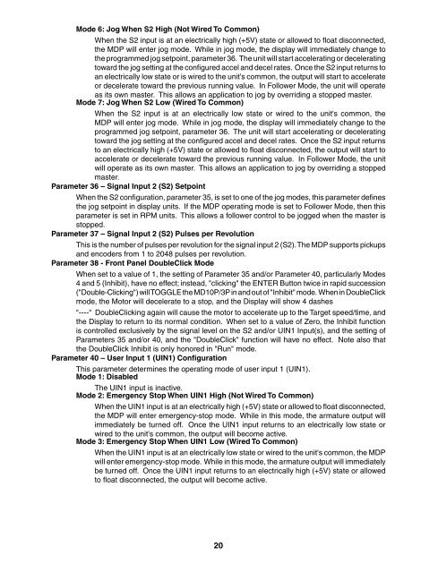
Mode 6: Jog When S2 High (Not Wired To Common)<br />
When the S2 input is at an electrically high (+5V) state or allowed to fl oat disconnected,<br />
the MDP will enter jog mode. While in jog mode, the display will immediately change to<br />
the programmed jog setpoint, parameter 36. The unit will start accelerating or decelerating<br />
toward the jog setting at the confi gured accel and decel rates. Once the S2 input returns to<br />
an electrically low state or is wired to the unit's common, the output will start to accelerate<br />
or decelerate toward the previous running value. In Follower Mode, the unit will operate<br />
as its own master. This allows an application to jog by overriding a stopped master.<br />
Mode 7: Jog When S2 Low (Wired To Common)<br />
When the S2 input is at an electrically low state or wired to the unit's common, the<br />
MDP will enter jog mode. While in jog mode, the display will immediately change to the<br />
programmed jog setpoint, parameter 36. The unit will start accelerating or decelerating<br />
toward the jog setting at the confi gured accel and decel rates. Once the S2 input returns<br />
to an electrically high (+5V) state or allowed to fl oat disconnected, the output will start to<br />
accelerate or decelerate toward the previous running value. In Follower Mode, the unit<br />
will operate as its own master. This allows an application to jog by overriding a stopped<br />
master.<br />
Parameter 36 – Signal Input 2 (S2) Setpoint<br />
When the S2 confi guration, parameter 35, is set to one of the jog modes, this parameter defi nes<br />
the jog setpoint in display units. If the MDP operating mode is set to Follower Mode, then this<br />
parameter is set in RPM units. This allows a follower <strong>control</strong> to be jogged when the master is<br />
stopped.<br />
Parameter 37 – Signal Input 2 (S2) Pulses per Revolution<br />
This is the number of pulses per revolution for the signal input 2 (S2). The MDP supports pickups<br />
and encoders from 1 to 2048 pulses per revolution.<br />
Parameter 38 - Front Panel DoubleClick Mode<br />
When set to a value of 1, the setting of Parameter 35 and/or Parameter 40, particularly Modes<br />
4 and 5 (Inhibit), have no effect; instead, "clicking" the ENTER Button twice in rapid succession<br />
("Double-Clicking") will TOGGLE the MD10P/3P in and out of "Inhibit" mode. When in DoubleClick<br />
mode, the Motor will decelerate to a stop, and the Display will show 4 dashes<br />
"----" DoubleClicking again will cause the motor to accelerate up to the Target speed/time, and<br />
the Display to return to its normal condition. When set to a value of Zero, the Inhibit function<br />
is <strong>control</strong>led exclusively by the signal level on the S2 and/or UIN1 Input(s), and the setting of<br />
Parameters 35 and/or 40, and the "DoubleClick" function will have no effect. Note also that<br />
the DoubleClick Inhibit is only honored in "Run" mode.<br />
Parameter 40 – User Input 1 (UIN1) Confi guration<br />
This parameter determines the operating mode of user input 1 (UIN1).<br />
Mode 1: Disabled<br />
The UIN1 input is inactive.<br />
Mode 2: Emergency Stop When UIN1 High (Not Wired To Common)<br />
When the UIN1 input is at an electrically high (+5V) state or allowed to fl oat disconnected,<br />
the MDP will enter emergency-stop mode. While in this mode, the armature output will<br />
immediately be turned off. Once the UIN1 input returns to an electrically low state or<br />
wired to the unit's common, the output will become active.<br />
Mode 3: Emergency Stop When UIN1 Low (Wired To Common)<br />
When the UIN1 input is at an electrically low state or wired to the unit's common, the MDP<br />
will enter emergency-stop mode. While in this mode, the armature output will immediately<br />
be turned off. Once the UIN1 input returns to an electrically high (+5V) state or allowed<br />
to fl oat disconnected, the output will become active.<br />
20


