

mdp control series - Omega Engineering
mdp control series - Omega Engineering
mdp control series - Omega Engineering

Create successful ePaper yourself
Turn your PDF publications into a flip-book with our unique Google optimized e-Paper software.
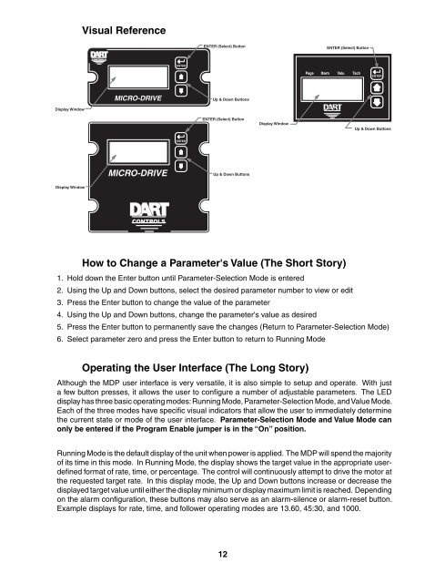
Display Window<br />
Display Window<br />
Visual Reference<br />
CONTROLS<br />
Page<br />
Ite<br />
m<br />
Valu<br />
Tach<br />
MICRO-DRIVE<br />
MICRO-DRIVE<br />
CONTROLS<br />
ENTER<br />
ENTER<br />
ENTER (Select) Button<br />
Up & Down Buttons<br />
ENTER (Select) Button<br />
Up & Down Buttons<br />
How to Change a Parameter's Value (The Short Story)<br />
1. Hold down the Enter button until Parameter-Selection Mode is entered<br />
2. Using the Up and Down buttons, select the desired parameter number to view or edit<br />
3. Press the Enter button to change the value of the parameter<br />
4. Using the Up and Down buttons, change the parameter's value as desired<br />
5. Press the Enter button to permanently save the changes (Return to Parameter-Selection Mode)<br />
6. Select parameter zero and press the Enter button to return to Running Mode<br />
Operating the User Interface (The Long Story)<br />
Although the MDP user interface is very versatile, it is also simple to setup and operate. With just<br />
a few button presses, it allows the user to confi gure a number of adjustable parameters. The LED<br />
display has three basic operating modes: Running Mode, Parameter-Selection Mode, and Value Mode.<br />
Each of the three modes have specifi c visual indicators that allow the user to immediately determine<br />
the current state or mode of the user interface. Parameter-Selection Mode and Value Mode can<br />
only be entered if the Program Enable jumper is in the “On” position.<br />
Running Mode is the default display of the unit when power is applied. The MDP will spend the majority<br />
of its time in this mode. In Running Mode, the display shows the target value in the appropriate userdefi<br />
ned format of rate, time, or percentage. The <strong>control</strong> will continuously attempt to drive the motor at<br />
the requested target rate. In this display mode, the Up and Down buttons increase or decrease the<br />
displayed target value until either the display minimum or display maximum limit is reached. Depending<br />
on the alarm confi guration, these buttons may also serve as an alarm-silence or alarm-reset button.<br />
Example displays for rate, time, and follower operating modes are 13.60, 45:30, and 1000.<br />
12<br />
Display Window<br />
Page<br />
ENTER (Select) Button<br />
Item Valu<br />
CONTROLS<br />
Tach<br />
ENTER<br />
Up & Down Buttons


