

mdp control series - Omega Engineering
mdp control series - Omega Engineering
mdp control series - Omega Engineering

Create successful ePaper yourself
Turn your PDF publications into a flip-book with our unique Google optimized e-Paper software.
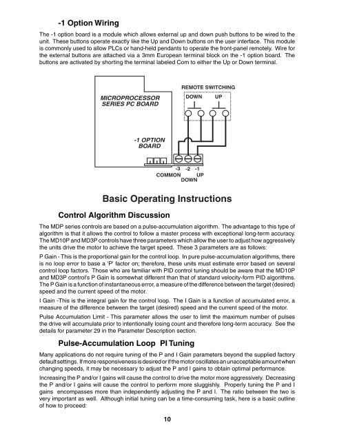
-1 Option Wiring<br />
The -1 option board is a module which allows external up and down push buttons to be wired to the<br />
unit. These buttons operate exactly like the Up and Down buttons on the user interface. This module<br />
is commonly used to allow PLCs or hand-held pendants to operate the front-panel remotely. Wire for<br />
the external buttons are attached via a 3mm European terminal block on the -1 option board. The<br />
buttons are activated by shorting the terminal labeled Com to either the Up or Down terminal.<br />
MICROPROCESSOR<br />
SERIES PC BOARD<br />
-1 OPTION<br />
BOARD<br />
Basic Operating Instructions<br />
Control Algorithm Discussion<br />
-3 -2 -1<br />
COMMON UP<br />
DOWN<br />
The MDP <strong>series</strong> <strong>control</strong>s are based on a pulse-accumulation algorithm. The advantage to this type of<br />
algorithm is that it allows the <strong>control</strong> to follow a master process with exceptional long-term accuracy.<br />
The MD10P and MD3P <strong>control</strong>s have three parameters which allow the user to adjust how aggressively<br />
the units drive the motor to achieve the target speed. These 3 parameters are as follows:<br />
P Gain - This is the proportional gain for the <strong>control</strong> loop. In pure pulse-accumulation algorithms, there<br />
is no loop error to base a 'P' factor on; therefore, these units must estimate error based on several<br />
<strong>control</strong> loop factors. Those who are familiar with PID <strong>control</strong> tuning should be aware that the MD10P<br />
and MD3P <strong>control</strong>'s P Gain is somewhat different than that of standard velocity-form PID algorithms.<br />
The P Gain is a function of instantaneous error, a measure of the difference between the target (desired)<br />
speed and the current speed of the motor.<br />
I Gain -This is the integral gain for the <strong>control</strong> loop. The I Gain is a function of accumulated error, a<br />
measure of the difference between the target (desired) speed and the current speed of the motor.<br />
Pulse Accumulation Limit - This parameter allows the user to limit the maximum number of pulses<br />
the drive will accumulate prior to intentionally losing count and therefore long-term accuracy. See the<br />
details for parameter 29 in the Parameter Description section.<br />
Pulse-Accumulation Loop PI Tuning<br />
Many applications do not require tuning of the P and I Gain parameters beyond the supplied factory<br />
default settings. If more responsiveness is desired or if the motor oscillates an unacceptable amount when<br />
changing speeds, it may be necessary to adjust the P and I gains to obtain optimal performance.<br />
Increasing the P and/or I gains will cause the <strong>control</strong> to drive the motor more aggressively. Decreasing<br />
the P and/or I gains will cause the <strong>control</strong> to perform more sluggishly. Properly tuning the P and I<br />
gains encompasses more than independently adjusting the P and I. The ratio between the two is<br />
very important as well. Although initial tuning can be a time-consuming task, here is a basic outline<br />
of how to proceed:<br />
10<br />
REMOTE SWITCHING<br />
DOWN UP


