

mdp control series - Omega Engineering
mdp control series - Omega Engineering
mdp control series - Omega Engineering

Create successful ePaper yourself
Turn your PDF publications into a flip-book with our unique Google optimized e-Paper software.
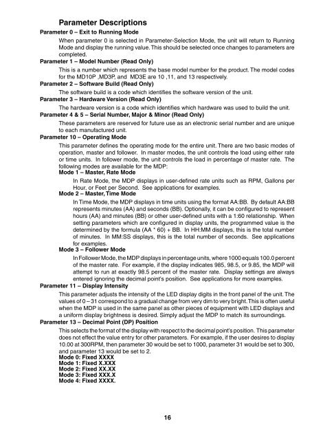
Parameter Descriptions<br />
Parameter 0 – Exit to Running Mode<br />
When parameter 0 is selected in Parameter-Selection Mode, the unit will return to Running<br />
Mode and display the running value. This should be selected once changes to parameters are<br />
completed.<br />
Parameter 1 – Model Number (Read Only)<br />
This is a number which represents the base model number for the product. The model codes<br />
for the MD10P ,MD3P, and MD3E are 10 ,11, and 13 respectively.<br />
Parameter 2 – Software Build (Read Only)<br />
The software build is a code which identifi es the software version of the unit.<br />
Parameter 3 – Hardware Version (Read Only)<br />
The hardware version is a code which identifi es which hardware was used to build the unit.<br />
Parameter 4 & 5 – Serial Number, Major & Minor (Read Only)<br />
These parameters are reserved for future use as an electronic serial number and are unique<br />
to each manufactured unit.<br />
Parameter 10 – Operating Mode<br />
This parameter defi nes the operating mode for the entire unit. There are two basic modes of<br />
operation, master and follower. In master modes, the unit <strong>control</strong>s the load using either rate<br />
or time units. In follower mode, the unit <strong>control</strong>s the load in percentage of master rate. The<br />
following modes are available for the MDP:<br />
Mode 1 – Master, Rate Mode<br />
In Rate Mode, the MDP displays in user-defi ned rate units such as RPM, Gallons per<br />
Hour, or Feet per Second. See applications for examples.<br />
Mode 2 – Master, Time Mode<br />
In Time Mode, the MDP displays in time units using the format AA:BB. By default AA:BB<br />
represents minutes (AA) and seconds (BB). Optionally, it can be confi gured to represent<br />
hours (AA) and minutes (BB) or other user-defi ned units with a 1:60 relationship. When<br />
setting parameters which are confi gured in display units, the programmed value is the<br />
determined by the formula (AA * 60) + BB. In HH:MM displays, this is the total number<br />
of minutes. In MM:SS displays, this is the total number of seconds. See applications<br />
for examples.<br />
Mode 3 – Follower Mode<br />
In Follower Mode, the MDP displays in percentage units, where 1000 equals 100.0 percent<br />
of the master rate. For example, if the display indicates 985, 98.5, or 9.85, the MDP will<br />
attempt to run at exactly 98.5 percent of the master rate. Display settings are always<br />
entered ignoring the decimal point's position. See applications for more examples.<br />
Parameter 11 – Display Intensity<br />
This parameter adjusts the intensity of the LED display digits in the front panel of the unit. The<br />
values of 0 – 31 correspond to a gradual change from very dim to very bright. This is often useful<br />
when the MDP is used in the same panel as other pieces of equipment with LED displays and<br />
a uniform display brightness is desired. Simply adjust the MDP to match its surroundings.<br />
Parameter 13 – Decimal Point (DP) Position<br />
This selects the format of the display with respect to the decimal point’s position. This parameter<br />
does not effect the value entry for other parameters. For example, if the user desires to display<br />
10.00 at 300RPM, then parameter 30 would be set to 1000, parameter 31 would be set to 300,<br />
and parameter 13 would be set to 2.<br />
Mode 0: Fixed XXXX<br />
Mode 1: Fixed X.XXX<br />
Mode 2: Fixed XX.XX<br />
Mode 3: Fixed XXX.X<br />
Mode 4: Fixed XXXX.<br />
16


