Intel 64 and IA-32 Architectures Software Developer's Manual
Intel 64 and IA-32 Architectures Software Developer's Manual
Intel 64 and IA-32 Architectures Software Developer's Manual

Create successful ePaper yourself
Turn your PDF publications into a flip-book with our unique Google optimized e-Paper software.
<strong>Intel</strong> ® <strong>64</strong> <strong>and</strong> <strong>IA</strong>-<strong>32</strong> <strong>Architectures</strong><br />
<strong>Software</strong> Developer’s <strong>Manual</strong><br />
Documentation Changes<br />
October 2006<br />
Notice: The <strong>Intel</strong> ® <strong>64</strong> <strong>and</strong> <strong>IA</strong>-<strong>32</strong> architectures may contain design defects or errors known as<br />
errata that may cause the product to deviate from published specifications. Current characterized<br />
errata are documented in the specification updates.<br />
Document Number: 252046-018
INFORMATION IN THIS DOCUMENT IS PROVIDED IN CONNECTION WITH INTEL ® PRODUCTS. NO LICENSE, EXPRESS OR IMPLIED,<br />
BY ESTOPPEL OR OTHERWISE, TO ANY INTELLECTUAL PROPERTY RIGHTS IS GRANTED BY THIS DOCUMENT. EXCEPT AS<br />
PROVIDED IN INTEL'S TERMS AND CONDITIONS OF SALE FOR SUCH PRODUCTS, INTEL ASSUMES NO L<strong>IA</strong>BILITY WHATSOEVER,<br />
AND INTEL DISCLAIMS ANY EXPRESS OR IMPLIED WARRANTY, RELATING TO SALE AND/OR USE OF INTEL PRODUCTS INCLUDING<br />
L<strong>IA</strong>BILITY OR WARRANTIES RELATING TO FITNESS FOR A PARTICULAR PURPOSE, MERCHANTABILITY, OR INFRINGEMENT OF ANY<br />
PATENT, COPYRIGHT OR OTHER INTELLECTUAL PROPERTY RIGHT. <strong>Intel</strong> products are not intended for use in medical, life saving,<br />
or life sustaining applications.<br />
<strong>Intel</strong> may make changes to specifications <strong>and</strong> product descriptions at any time, without notice.<br />
Designers must not rely on the absence or characteristics of any features or instructions marked “reserved” or “undefined.” <strong>Intel</strong><br />
reserves these for future definition <strong>and</strong> shall have no responsibility whatsoever for conflicts or incompatibilities arising from future<br />
changes to them.<br />
Contact your local <strong>Intel</strong> sales office or your distributor to obtain the latest specifications <strong>and</strong> before placing your product order.<br />
I 2 C is a two-wire communications bus/protocol developed by Philips. SMBus is a subset of the I 2 C bus/protocol <strong>and</strong> was developed<br />
by <strong>Intel</strong>. Implementations of the I 2 C bus/protocol may require licenses from various entities, including Philips Electronics N.V. <strong>and</strong><br />
North American Philips Corporation.<br />
<strong>Intel</strong>, Pentium, Celeron, <strong>Intel</strong> SpeedStep, <strong>Intel</strong> Xeon, <strong>Intel</strong> <strong>64</strong>, <strong>and</strong> the <strong>Intel</strong> logo, <strong>and</strong> the <strong>Intel</strong> logo are trademarks or registered<br />
trademarks of <strong>Intel</strong> Corporation or its subsidiaries in the United States <strong>and</strong> other countries.<br />
*Other names <strong>and</strong> br<strong>and</strong>s may be claimed as the property of others.<br />
Copyright © 2002–2006, <strong>Intel</strong> Corporation. All rights reserved.<br />
2 <strong>Intel</strong> ® <strong>64</strong> <strong>and</strong> <strong>IA</strong>-<strong>32</strong> <strong>Architectures</strong> <strong>Software</strong> Developer’s <strong>Manual</strong> Documentation Changes
Contents<br />
Preface ............................................................................................... 5<br />
Summary Table of Changes ................................................................... 6<br />
Documentation Changes ........................................................................ 8<br />
<strong>Intel</strong> ® <strong>64</strong> <strong>and</strong> <strong>IA</strong>-<strong>32</strong> <strong>Architectures</strong> <strong>Software</strong> Developer’s <strong>Manual</strong> Documentation Changes 3
Revision History<br />
Version Description Date<br />
-001 • Initial Release November 2002<br />
-002 • Added 1-10 Documentation Changes.<br />
• Removed old Documentation Changes items that already have been<br />
incorporated in the published <strong>Software</strong> Developer’s manual<br />
-003 • Added 9 -17 Documentation Changes.<br />
• Removed Documentation Change #6 - References to bits Gen <strong>and</strong> Len<br />
Deleted.<br />
• Removed Documentation Change #4 - VIF Information Added to CLI<br />
Discussion.<br />
-004 • Removed Documentation changes 1-17.<br />
• Added Documentation changes 1-24.<br />
-005 • Removed Documentation Changes 1-24.<br />
• Added Documentation Changes 1-15.<br />
December 2002<br />
February 2003<br />
June 2003<br />
September 2003<br />
-006 • Added Documentation Changes 16- 34. November 2003<br />
-007 • Updated Documentation changes 14, 16, 17, <strong>and</strong> 28.<br />
• Added Documentation Changes 35-45.<br />
-008 • Removed Documentation Changes 1-45.<br />
• Added Documentation Changes 1-5.<br />
January 2004<br />
March 2004<br />
-009 • Added Documentation Changes 7-27. May 2004<br />
-010 • Removed Documentation Changes 1-27.<br />
• Added Documentation Changes 1.<br />
August 2004<br />
-011 • Added Documentation Changes 2-28. November 2004<br />
-012 • Removed Documentation Changes 1-28.<br />
• Added Documentation Changes 1-16.<br />
-013 • Updated title.<br />
• There are no Documentation Changes for this revision of the document.<br />
March 2005<br />
July 2005<br />
-014 • Added Documentation Changes 1-21. September 2005<br />
-015 • Removed Documentation Changes 1-21.<br />
• Added Documentation Changes 1-20.<br />
March 9, 2006<br />
-016 • Added Documentation changes 21-23. March 27, 2006<br />
-017 • Removed Documentation Changes 1-23.<br />
• Added Documentation Changes 1-36.<br />
September 2006<br />
-018 • Added Documentation Changes 37-42. October 2006<br />
4 <strong>Intel</strong> ® <strong>64</strong> <strong>and</strong> <strong>IA</strong>-<strong>32</strong> <strong>Architectures</strong> <strong>Software</strong> Developer’s <strong>Manual</strong> Documentation Changes
Preface<br />
Preface<br />
This document is an update to the specifications contained in the Affected Documents/<br />
Related Documents table below. This document is a compilation of documentation<br />
changes. It is intended for hardware system manufacturers <strong>and</strong> software developers of<br />
applications, operating systems, or tools.<br />
Affected Documents/Related Documents<br />
Document Title<br />
<strong>Intel</strong> ® <strong>64</strong> <strong>and</strong> <strong>IA</strong>-<strong>32</strong> <strong>Architectures</strong> <strong>Software</strong> Developer’s <strong>Manual</strong>, Volume 1:<br />
Basic Architecture<br />
<strong>Intel</strong> ® <strong>64</strong> <strong>and</strong> <strong>IA</strong>-<strong>32</strong> <strong>Architectures</strong> <strong>Software</strong> Developer’s <strong>Manual</strong>, Volume 2A:<br />
Instruction Set Reference, A-M<br />
<strong>Intel</strong> ® <strong>64</strong> <strong>and</strong> <strong>IA</strong>-<strong>32</strong> <strong>Architectures</strong> <strong>Software</strong> Developer’s <strong>Manual</strong>, Volume 2B:<br />
Instruction Set Reference, N-Z<br />
<strong>Intel</strong> ® <strong>64</strong> <strong>and</strong> <strong>IA</strong>-<strong>32</strong> <strong>Architectures</strong> <strong>Software</strong> Developer’s <strong>Manual</strong>, Volume 3A:<br />
System Programming Guide<br />
<strong>Intel</strong> ® <strong>64</strong> <strong>and</strong> <strong>IA</strong>-<strong>32</strong> <strong>Architectures</strong> <strong>Software</strong> Developer’s <strong>Manual</strong>, Volume 3B:<br />
System Programming Guide<br />
Document<br />
Number<br />
253665<br />
253666<br />
253667<br />
253668<br />
253669<br />
Nomenclature<br />
Documentation Changes include errors or omissions from the current published<br />
specifications. These changes will be incorporated in the next release of the <strong>Software</strong><br />
Development <strong>Manual</strong>.<br />
<strong>Intel</strong> ® <strong>64</strong> <strong>and</strong> <strong>IA</strong>-<strong>32</strong> <strong>Architectures</strong> <strong>Software</strong> Developer’s <strong>Manual</strong> Documentation Changes 5
Summary Table of Changes<br />
Summary Table of Changes<br />
The following table indicates documentation changes which apply to the <strong>IA</strong>-<strong>32</strong> <strong>Intel</strong> ®<br />
architecture. This table uses the following notations:<br />
Codes Used in Summary Table<br />
Change bar to left of table row indicates this erratum is either new or modified from<br />
the previous version of the document.<br />
Summary Table of Documentation Changes (Sheet 1 of 2)<br />
Number<br />
Documentation Changes<br />
1 MOV—Move to/from Control Registers<br />
2 XTPR Update Control information added<br />
3 Table on reserved bit checking has been corrected<br />
4 MSR_THERM2_CTL description updated<br />
5 Updated CPUID input format<br />
6 Flag information added for POPF/POPFD/POPFQ<br />
7 Restriction added for total size field, microcode update format<br />
8 Flag check corrected<br />
9 REP/REPE/REPZ/REPNE/REPNZ summary table updated<br />
10 Documentation of CMASK bit range corrected<br />
11 Note defines additional restrictions on APIC DFR programming<br />
12 Tables documenting MCA error codes updated<br />
13 PUSHA/PUSHAD information updated<br />
14 VMCALL pseudocode updated<br />
15 Information on code fetches in uncacheable memory updated<br />
16 PUSH description updated<br />
17 IRET/IRETD pseudocode updated<br />
18 BSR summary table updated<br />
19 SYSCALL <strong>and</strong> SYSRET pseudocode updated<br />
20 VMX Debug exceptions paragraph deleted<br />
21 FLD list of exceptions updated<br />
22 CPUID register reference corrected<br />
23 UCOMISS range corrected in pseudocode<br />
24 CR information updated<br />
25 VMXON opcode corrected<br />
26 MSR references updated<br />
27 CR0.WP coverage updated<br />
28 Illegal register address flag description updated<br />
29 CPUID call reference corrected<br />
30 Note describing semaphore restrictions added<br />
6 <strong>Intel</strong> ® <strong>64</strong> <strong>and</strong> <strong>IA</strong>-<strong>32</strong> <strong>Architectures</strong> <strong>Software</strong> Developer’s <strong>Manual</strong> Documentation Changes
Summary Table of Changes<br />
Summary Table of Documentation Changes (Sheet 2 of 2)<br />
Number<br />
Documentation Changes<br />
31 DAS pseudocode updated<br />
<strong>32</strong> Entries added to CACHE-TLB table<br />
33 Updated MOV to CR8 information<br />
34 Information on ENTER instruction updated<br />
35 Microcode update sections improved<br />
36 Incorrect calls to CPUID.1:ECX[bit 9] have been corrected<br />
37 String operation <strong>and</strong> EFLAGS.RF interactions clarified<br />
38 MSR references corrected<br />
39 Description of VM-entry checks on VM-execution control fields updated<br />
40 STI, MOVSS/POPSS blocking behavior clarified<br />
41 Correction for information on PEBS record size<br />
42 Guest SMBASE entry added to table<br />
<strong>Intel</strong> ® <strong>64</strong> <strong>and</strong> <strong>IA</strong>-<strong>32</strong> <strong>Architectures</strong> <strong>Software</strong> Developer’s <strong>Manual</strong> Documentation Changes 7
Documentation Changes<br />
Documentation Changes<br />
1. MOV—Move to/from Control Registers<br />
In Chapter 3, “MOV—Move to/from Control Registers” of the <strong>Intel</strong> ® <strong>64</strong> <strong>and</strong> <strong>IA</strong>-<strong>32</strong><br />
<strong>Architectures</strong> <strong>Software</strong> Developer’s <strong>Manual</strong>, Volume 2A; the summary table has been<br />
corrected. The updated table is reproduced below. Change bars mark corrected lines.<br />
-------------------------------------------------------------------<br />
Opcode Instruction <strong>64</strong>-Bit<br />
Mode<br />
Compat/<br />
Leg Mode<br />
Description<br />
0F 22 /r MOV CR0,r<strong>32</strong> N.E. Valid Move r<strong>32</strong> to CR0.<br />
0F 22 /r MOV CR0,r<strong>64</strong> Valid N.E. Move r<strong>64</strong> to extended CR0.<br />
0F 22 /r MOV CR2,r<strong>32</strong> N.E. Valid Move r<strong>32</strong> to CR2.<br />
0F 22 /r MOV CR2,r<strong>64</strong> Valid N.E. Move r<strong>64</strong> to extended CR2.<br />
0F 22 /r MOV CR3,r<strong>32</strong> N.E. Valid Move r<strong>32</strong> to CR3.<br />
0F 22 /r MOV CR3,r<strong>64</strong> Valid N.E. Move r<strong>64</strong> to extended CR3.<br />
0F 22 /r MOV CR4,r<strong>32</strong> N.E. Valid Move r<strong>32</strong> to CR4.<br />
0F 22 /r MOV CR4,r<strong>64</strong> Valid N.E. Move r<strong>64</strong> to extended CR4.<br />
0F 20 /r MOV r<strong>32</strong>,CR0 N.E. Valid Move CR0 to r<strong>32</strong>.<br />
0F 20 /r MOV r<strong>64</strong>,CR0 Valid N.E. Move extended CR0 to r<strong>64</strong>.<br />
0F 20 /r MOV r<strong>32</strong>,CR2 N.E. Valid Move CR2 to r<strong>32</strong>.<br />
0F 20 /r MOV r<strong>64</strong>,CR2 Valid N.E. Move extended CR2 to r<strong>64</strong>.<br />
0F 20 /r MOV r<strong>32</strong>,CR3 N.E. Valid Move CR3 to r<strong>32</strong>.<br />
0F 20 /r MOV r<strong>64</strong>,CR3 Valid N.E. Move extended CR3 to r<strong>64</strong>.<br />
0F 20 /r MOV r<strong>32</strong>,CR4 N.E. Valid Move CR4 to r<strong>32</strong>.<br />
0F 20 /r MOV r<strong>64</strong>,CR4 Valid N.E. Move extended CR4 to r<strong>64</strong>.<br />
0F 20 /r MOV r<strong>32</strong>,CR8 N.E. N.E. Move CR8 to r<strong>32</strong>.<br />
REX + 0F 20 /r MOV r<strong>64</strong>,CR8 Valid N.E. Move extended CR8 to r<strong>64</strong>. 1<br />
NOTE:<br />
1. MOV CR* instructions, except for MOV CR8, are serializing instructions. MOV CR8 is not<br />
architecturally defined as a serializing instruction. For more information, see Chapter 7 in <strong>Intel</strong> ® <strong>64</strong><br />
<strong>and</strong> <strong>IA</strong>-<strong>32</strong> <strong>Architectures</strong> <strong>Software</strong> Developer’s <strong>Manual</strong>, Volume 3A.<br />
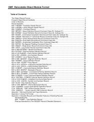
2. XTPR Update Control information added<br />
Figure 3-6 <strong>and</strong> Table 3-15 in Chapter 3, “CPUID—CPU Identification” of the <strong>Intel</strong> ® <strong>64</strong> <strong>and</strong><br />
<strong>IA</strong>-<strong>32</strong> <strong>Architectures</strong> <strong>Software</strong> Developer’s <strong>Manual</strong>, Volume 2A, information on the CPUID<br />
xTPR update control bit has been added.<br />
The information is reproduced below.<br />
-------------------------------------------------------------------<br />
8 <strong>Intel</strong> ® <strong>64</strong> <strong>and</strong> <strong>IA</strong>-<strong>32</strong> <strong>Architectures</strong> <strong>Software</strong> Developer’s <strong>Manual</strong> Documentation Changes
Documentation Changes<br />
<br />
<br />
<br />
<br />
<br />
<br />
<br />
<br />
<br />
<br />
<br />
<br />
<br />
<br />
<br />
<br />
<br />
<br />
<br />
<br />
<br />
<br />
<br />
<br />
Figure 3-6. Extended Feature Information Returned in the ECX Register<br />
Table 3-15. More on Extended Feature Information Returned in the ECX Register<br />
Bit # Mnemonic Description<br />
.... .... .....[not all lines in table are shown]<br />
13 CMPXCHG16B CMPXCHG16B Available. A value of 1 indicates that the feature is<br />
available. See the “CMPXCHG8B/CMPXCHG16B—Compare <strong>and</strong><br />
Exchange Bytes” section in this chapter for a description.<br />
14 xTPR Update<br />
Control<br />
31 - 15 Reserved Reserved<br />
xTPR Update Control. A value of 1 indicates that the processor<br />
supports changing <strong>IA</strong><strong>32</strong>_MISC_ENABLES[bit 23].<br />
-------------------------------------------------------------------<br />
Information on the CPUID xTPR update control function has also been added to the<br />
discussions of <strong>IA</strong><strong>32</strong>_MISC_ENABLES[bit 23] in Appendix B (Tables B-1, B-2, B-5) of the<br />
<strong>Intel</strong> ® <strong>64</strong> <strong>and</strong> <strong>IA</strong>-<strong>32</strong> <strong>Architectures</strong> <strong>Software</strong> Developer’s <strong>Manual</strong>, Volume 3B.<br />
The added information is reproduced below.<br />
-------------------------------------------------------------------<br />
Register<br />
Address<br />
Hex<br />
Dec<br />
Register Name<br />
Fields <strong>and</strong> Flags<br />
Model<br />
Availability<br />
Shared/<br />
Unique<br />
Bit Description<br />
23 xTPR Message Disable (R/W).<br />
When set to 1, xTPR messages are<br />
disabled. xTPR messages are<br />
optional messages that allow the<br />
processor to inform the chipset of<br />
its priority. The default is<br />
processor specific.<br />
<strong>Intel</strong> ® <strong>64</strong> <strong>and</strong> <strong>IA</strong>-<strong>32</strong> <strong>Architectures</strong> <strong>Software</strong> Developer’s <strong>Manual</strong> Documentation Changes 9
Documentation Changes<br />
3. Table on reserved bit checking has been corrected<br />
Table 3-5 of the <strong>Intel</strong> ® <strong>64</strong> <strong>and</strong> <strong>IA</strong>-<strong>32</strong> <strong>Architectures</strong> <strong>Software</strong> Developer’s <strong>Manual</strong>, Volume<br />
3A has been corrected. The corrections were to check bit values. The table is reproduced<br />
below. See the change bars for impacted lines.<br />
-------------------------------------------------------------------<br />
Mode Paging Mode Paging Structure Check Bits<br />
<strong>32</strong>-bit 4-KByte pages (PAE = 0, PSE = 0) PDE <strong>and</strong> PT No reserved bits checked<br />
4-MByte page (PAE = 0, PSE = 1) PDE Bit [21]<br />
4-KByte page (PAE = 0, PSE = 1) PDE No reserved bits checked<br />
4-KByte <strong>and</strong> 4-MByte page (PAE =<br />
0, PSE = 1)<br />
PTE<br />
No reserved bits checked<br />
4-KByte <strong>and</strong> 2-MByte pages (PAE =<br />
1, PSE = x)<br />
PDP table entry Bits [63:40] & [8:5] & [2:1]<br />
2-MByte page (PAE = 1, PSE = x) PDE Bits [62:40] & [20:13]<br />
4-KByte pages (PAE = 1, PSE = x) PDE Bits [62:40]<br />
4-KByte pages (PAE = 1, PSE = x) PTE Bits [62:40]<br />
<strong>64</strong>-bit 4-KByte <strong>and</strong> 2-MByte pages (PAE =<br />
1, PSE = x)<br />
4-KByte <strong>and</strong> 2-MByte pages (PAE =<br />
1, PSE = x)<br />
PML4E Bits [51:40]<br />
PDPTE Bits [51:40]<br />
2-MByte page (PAE = 1, PSE = x) PDE, 2-MByte page Bits [51:40] & [20:13]<br />
4-KByte pages (PAE = 1, PSE = x) PDE, 4-KByte page Bits [51:40]<br />
4-KByte pages (PAE = 1, PSE = x) PTE Bits [51:40]<br />
NOTE:<br />
x = Bit does not impact behavior.<br />
4. MSR_THERM2_CTL description updated<br />
In Table B-2 of the <strong>Intel</strong> ® <strong>64</strong> <strong>and</strong> <strong>IA</strong>-<strong>32</strong> <strong>Architectures</strong> <strong>Software</strong> Developer’s <strong>Manual</strong>,<br />
Volume 3B, the description for MSR_THERM2_CTL(address 19DH) has been updated. The<br />
update targets Family F processors. See the table segment below.<br />
-------------------------------------------------------------------<br />
Register<br />
Address<br />
Register Name<br />
Fields <strong>and</strong> Flags<br />
Model<br />
Availability<br />
Shared/<br />
Unique<br />
Hex Dec<br />
Bit Description<br />
.... ... .... .... .... ....<br />
19DH 413 IMSR_THERM2_CTL Thermal Monitor 2 Control.<br />
3 Shared For Family F, Model 3 processors:<br />
When read, specifies the value of<br />
the target TM2 transition last<br />
written. When set, it sets the next<br />
target value for TM2 transition.<br />
10 <strong>Intel</strong> ® <strong>64</strong> <strong>and</strong> <strong>IA</strong>-<strong>32</strong> <strong>Architectures</strong> <strong>Software</strong> Developer’s <strong>Manual</strong> Documentation Changes
Documentation Changes<br />
Register<br />
Address<br />
Hex<br />
Dec<br />
Register Name<br />
Fields <strong>and</strong> Flags<br />
Model<br />
Availability<br />
Shared/<br />
Unique<br />
Bit Description<br />
4, 6 Shared For Family F, Model 4 <strong>and</strong> Model 6<br />
processors: When read, specifies<br />
the value of the target TM2<br />
transition last written. Writes may<br />
cause #GP exceptions.<br />
5. Updated CPUID input format<br />
Some CPUID inputs require two input values. Documentation of the CPUID input format<br />
has been updated to reflect this requirement.<br />
See the summary table below (from Chapter 3, “CPUID—CPU Identification”, of the<br />
<strong>Intel</strong> ® <strong>64</strong> <strong>and</strong> <strong>IA</strong>-<strong>32</strong> <strong>Architectures</strong> <strong>Software</strong> Developer’s <strong>Manual</strong>, Volume 2A).<br />
-------------------------------------------------------------------<br />
CPUID—CPU Identification<br />
Opcode Instruction <strong>64</strong>-Bit<br />
Mode<br />
Compat/<br />
Leg Mode<br />
Description<br />
0F A2 CPUID Valid Valid Returns processor<br />
identification <strong>and</strong> feature<br />
information to the EAX, EBX,<br />
ECX, <strong>and</strong> EDX registers, as<br />
determined by input entered<br />
in EAX (<strong>and</strong>, in some cases,<br />
ECX).<br />
.-------------------------------------------------------------------<br />
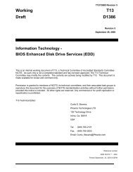
In addition, the input format is summarized in a figure located in the first chapter of each<br />
volume; this figure is reproduced below.<br />
-------------------------------------------------------------------<br />
<strong>Intel</strong> ® <strong>64</strong> <strong>and</strong> <strong>IA</strong>-<strong>32</strong> <strong>Architectures</strong> <strong>Software</strong> Developer’s <strong>Manual</strong> Documentation Changes 11
Documentation Changes<br />
.<br />
<br />
<br />
<br />
<br />
<br />
<br />
<br />
<br />
<br />
<br />
<br />
<br />
<br />
<br />
<br />
<br />
<br />
<br />
<br />
Figure 18-11. Syntax for CPUID, CR, <strong>and</strong> MSR Data Presentation<br />
------------------------------------------------------------------<br />
From Chapter 7 of the <strong>Intel</strong> ® <strong>64</strong> <strong>and</strong> <strong>IA</strong>-<strong>32</strong> <strong>Architectures</strong> <strong>Software</strong> Developer’s <strong>Manual</strong>,<br />
Volume 3A), below is an example of a CPUID feature that requires two inputs. See the<br />
change bars <strong>and</strong> the footnote.<br />
-------------------------------------------------------------------<br />
7.7. Detecting Hardware Multi-Threading Support <strong>and</strong> Topology<br />
Use the CPUID instruction to detect the presence of hardware multi-threading support in<br />
a physical processor. The following can be interpreted:<br />
• Hardware Multi-Threading feature flag (CPUID.1:EDX[28] = 1) — Indicates<br />
when set that the physical package is capable of supporting Hyper-Threading<br />
Technology <strong>and</strong>/or multiple cores.<br />
• Logical processors per Package (CPUID.1:EBX[23:16]) — Indicates the<br />
maximum number of logical processors in a physical package. This represents the<br />
hardware capability as the processor has been manufactured. 1<br />
1. Operating system <strong>and</strong> BIOS may implement features that reduce the number of logical processors available<br />
in a platform to applications at runtime to less than the number of physical packages times the number of<br />
hardware-capable logical processors per package.<br />
12 <strong>Intel</strong> ® <strong>64</strong> <strong>and</strong> <strong>IA</strong>-<strong>32</strong> <strong>Architectures</strong> <strong>Software</strong> Developer’s <strong>Manual</strong> Documentation Changes
Documentation Changes<br />
• Cores per Package 1 (CPUID.(EAX=4, ECX=0 2 ):EAX[31:26] + 1 = Y) —<br />
Indicates the maximum number of processor cores (Y) in the physical package<br />
The CPUID feature flag may indicate support for hardware multi-threading when only<br />
one logical processor available in the package. In this case, the decimal value<br />
represented by bits 16 through 23 in the EBX register will have a value of 1.<br />
<strong>Software</strong> should note that the number of logical processors enabled by system software<br />
may be less than the value of “logical processors per package”. Similarly, the number of<br />
cores enabled by system software may be less than the value of “cores per package”.<br />
.. ... ....Text omitted here... ... ....<br />
6. Flag information added for POPF/POPFD/POPFQ<br />
In Chapter 4, “POPF/POPFD/POPFQ—Pop Stack” of the <strong>Intel</strong> ® <strong>64</strong> <strong>and</strong> <strong>IA</strong>-<strong>32</strong> <strong>Architectures</strong><br />
<strong>Software</strong> Developer’s <strong>Manual</strong>, Volume 2B, the flag information has been updated. The<br />
section is reprinted below with changes marked by change bars.<br />
-------------------------------------------------------------------<br />
POPF/POPFD/POPFQ—Pop Stack into EFLAGS Register<br />
Opcode Instruction <strong>64</strong>-Bit Compat/ Description<br />
Mode Leg Mode<br />
9D POPF Valid Valid Pop top of stack into lower 16 bits<br />
of EFLAGS.<br />
9D POPFD N.E. Valid Pop top of stack into EFLAGS.<br />
REX.W + 9D POPFQ Valid N.E. Pop top of stack <strong>and</strong> zero-extend<br />
into RFLAGS.<br />
Description<br />
Pops a doubleword (POPFD) from the top of the stack (if the current oper<strong>and</strong>-size<br />
attribute is <strong>32</strong>) <strong>and</strong> stores the value in the EFLAGS register, or pops a word from the top<br />
of the stack (if the oper<strong>and</strong>-size attribute is 16) <strong>and</strong> stores it in the lower 16 bits of the<br />
EFLAGS register (that is, the FLAGS register). These instructions reverse the operation<br />
of the PUSHF/PUSHFD instructions.<br />
The POPF (pop flags) <strong>and</strong> POPFD (pop flags double) mnemonics reference the same<br />
opcode. The POPF instruction is intended for use when the oper<strong>and</strong>-size attribute is 16;<br />
the POPFD instruction is intended for use when the oper<strong>and</strong>-size attribute is <strong>32</strong>. Some<br />
assemblers may force the oper<strong>and</strong> size to 16 for POPF <strong>and</strong> to <strong>32</strong> for POPFD. Others may<br />
treat the mnemonics as synonyms (POPF/POPFD) <strong>and</strong> use the setting of the oper<strong>and</strong>size<br />
attribute to determine the size of values to pop from the stack.<br />
The effect of POPF/POPFD on the EFLAGS register changes, depending on the mode of<br />
operation. When the processor is operating in protected mode at privilege level 0 (or in<br />
real-address mode, the equivalent to privilege level 0), all non-reserved flags in the<br />
EFLAGS register except RF 3 , VIP, VIF, <strong>and</strong> VM may be modified. VIP, VIF <strong>and</strong> VM remain<br />
unaffected.<br />
1. <strong>Software</strong> must check CPUID for its support of leaf 4 when implementing support for multi-core. If CPUID leaf<br />
4 is not available at runtime, software should h<strong>and</strong>le the situation as if there is only one core per package.<br />
2. Maximum number of cores in the physical package must be queried by executing CPUID with EAX =1 <strong>and</strong> a<br />
valid ECX input value. ECX input values start from 0.<br />
3. RF is always zero after execution of POPF. This is because POPF, like all instructions, clears RF as it begins to<br />
execute.<br />
<strong>Intel</strong> ® <strong>64</strong> <strong>and</strong> <strong>IA</strong>-<strong>32</strong> <strong>Architectures</strong> <strong>Software</strong> Developer’s <strong>Manual</strong> Documentation Changes 13
Documentation Changes<br />
When operating in protected mode with a privilege level greater than 0, but less than or<br />
equal to IOPL, all flags can be modified except the IOPL field <strong>and</strong> VIP, VIF, <strong>and</strong> VM. Here,<br />
the IOPL flags are unaffected, the VIP <strong>and</strong> VIF flags are cleared, <strong>and</strong> the VM flag is<br />
unaffected. The interrupt flag (IF) is altered only when executing at a level at least as<br />
privileged as the IOPL. If a POPF/POPFD instruction is executed with insufficient<br />
privilege, an exception does not occur but privileged bits do not change.<br />
When operating in virtual-8086 mode, the IOPL must be equal to 3 to use POPF/POPFD<br />
instructions; VM, RF, IOPL, VIP, <strong>and</strong> VIF are unaffected. If the IOPL is less than 3, POPF/<br />
POPFD causes a general-protection exception (#GP).<br />
In <strong>64</strong>-bit mode, use REX.W to pop the top of stack to RFLAGS. The mnemonic assigned<br />
is POPFQ (note that the <strong>32</strong>-bit oper<strong>and</strong> is not encodable). POPFQ pops <strong>64</strong> bits from the<br />
stack, loads the lower <strong>32</strong> bits into RFLAGS, <strong>and</strong> zero extends the upper bits of RFLAGS.<br />
See Chapter 3 of the <strong>Intel</strong> ® <strong>64</strong> <strong>and</strong> <strong>IA</strong>-<strong>32</strong> <strong>Architectures</strong> <strong>Software</strong> Developer’s <strong>Manual</strong>,<br />
Volume 1, for more information about the EFLAGS registers.<br />
Operation<br />
IF VM = 0 (* Not in Virtual-8086 Mode *)<br />
THEN IF CPL = 0<br />
THEN<br />
IF Oper<strong>and</strong>Size = <strong>32</strong>;<br />
THEN<br />
EFLAGS ← Pop(); (* <strong>32</strong>-bit pop *)<br />
(* All non-reserved flags except RF, VIP, VIF, <strong>and</strong> VM can be modified;<br />
VIP <strong>and</strong> VIF are cleared; RF, VM, <strong>and</strong> all reserved bits are unaffected. *)<br />
ELSE IF (Oper<strong>and</strong>size = <strong>64</strong>)<br />
RFLAGS = Pop(); (* <strong>64</strong>-bit pop *)<br />
(* All non-reserved flags except RF, VIP, VIF, <strong>and</strong> VM can be modified; VIP<br />
<strong>and</strong> VIF are cleared; RF, VM, <strong>and</strong> all reserved bits are unaffected.*)<br />
ELSE (* Oper<strong>and</strong>Size = 16 *)<br />
EFLAGS[15:0] ← Pop(); (* 16-bit pop *)<br />
(* All non-reserved flags can be modified. *)<br />
FI;<br />
ELSE (* CPL > 0 *)<br />
IF Oper<strong>and</strong>Size = <strong>32</strong><br />
THEN<br />
IF CPL > IOPL<br />
THEN<br />
EFLAGS ← Pop(); (* <strong>32</strong>-bit pop *)<br />
(* All non-reserved bits except IF, IOPL, RF, VIP, <strong>and</strong><br />
VIF can be modified; IF, IOPL, RF, VM, <strong>and</strong> all reserved<br />
bits are unaffected; VIP <strong>and</strong> VIF are cleared. *)<br />
ELSE<br />
EFLAGS ← Pop(); (* <strong>32</strong>-bit pop *)<br />
(* All non-reserved bits except IOPL, RF, VIP, <strong>and</strong> VIF can be<br />
modified; IOPL, RF, VM, <strong>and</strong> all reserved bits are<br />
unaffected; VIP <strong>and</strong> VIF are cleared. *)<br />
FI;<br />
ELSE IF (Oper<strong>and</strong>size = <strong>64</strong>)<br />
IF CPL > IOPL<br />
THEN<br />
RFLAGS ← Pop(); (* <strong>64</strong>-bit pop *)<br />
(* All non-reserved bits except IF, IOPL, RF, VIP, <strong>and</strong><br />
VIF can be modified; IF, IOPL, RF, VM, <strong>and</strong> all reserved<br />
14 <strong>Intel</strong> ® <strong>64</strong> <strong>and</strong> <strong>IA</strong>-<strong>32</strong> <strong>Architectures</strong> <strong>Software</strong> Developer’s <strong>Manual</strong> Documentation Changes
Documentation Changes<br />
FI;<br />
bits are unaffected; VIP <strong>and</strong> VIF are cleared. *)<br />
ELSE<br />
RFLAGS ← Pop(); (* <strong>64</strong>-bit pop *)<br />
(* All non-reserved bits except IOPL, RF, VIP, <strong>and</strong> VIF can be<br />
modified; IOPL, RF, VM, <strong>and</strong> all reserved bits are<br />
unaffected; VIP <strong>and</strong> VIF are cleared. *)<br />
FI;<br />
ELSE (* Oper<strong>and</strong>Size = 16 *)<br />
EFLAGS[15:0] ← Pop(); (* 16-bit pop *)<br />
(* All non-reserved bits except IOPL can be modified; IOPL <strong>and</strong> all<br />
reserved bits are unaffected. *)<br />
FI;<br />
FI;<br />
ELSE (* In Virtual-8086 Mode *)<br />
IF IOPL = 3<br />
THEN IF Oper<strong>and</strong>Size = <strong>32</strong><br />
THEN<br />
EFLAGS ← Pop();<br />
(* All non-reserved bits except VM, RF, IOPL, VIP, <strong>and</strong> VIF can be<br />
modified; VM, RF, IOPL, VIP, VIF, <strong>and</strong> all reserved bits are unaffected. *)<br />
ELSE<br />
EFLAGS[15:0] ← Pop(); FI;<br />
(* All non-reserved bits except IOPL can be modified;<br />
IOPL <strong>and</strong> all reserved bits are unaffected. *)<br />
ELSE (* IOPL < 3 *)<br />
#GP(0); (* Trap to virtual-8086 monitor. *)<br />
FI;<br />
FI;<br />
Flags Affected<br />
All flags may be affected; see the Operation section for details.<br />
Protected Mode Exceptions<br />
#SS(0)<br />
If the top of stack is not within the stack segment.<br />
#PF(fault-code) If a page fault occurs.<br />
#AC(0)<br />
If an unaligned memory reference is made while the current privilege<br />
level is 3 <strong>and</strong> alignment checking is enabled.<br />
Real-Address Mode Exceptions<br />
#SS<br />
If the top of stack is not within the stack segment.<br />
Virtual-8086 Mode Exceptions<br />
#GP(0) If the I/O privilege level is less than 3.<br />
If an attempt is made to execute the POPF/POPFD instruction with<br />
an oper<strong>and</strong>-size override prefix.<br />
#SS(0)<br />
If the top of stack is not within the stack segment.<br />
#PF(fault-code) If a page fault occurs.<br />
#AC(0)<br />
If an unaligned memory reference is made while alignment<br />
checking is enabled.<br />
<strong>Intel</strong> ® <strong>64</strong> <strong>and</strong> <strong>IA</strong>-<strong>32</strong> <strong>Architectures</strong> <strong>Software</strong> Developer’s <strong>Manual</strong> Documentation Changes 15
Documentation Changes<br />
Compatibility Mode Exceptions<br />
Same as for protected mode exceptions.<br />
<strong>64</strong>-Bit Mode Exceptions<br />
#GP(0)<br />
#SS(U)<br />
#PF(fault-code)<br />
#AC(0)<br />
If the memory address is in a non-canonical form.<br />
If the stack address is in a non-canonical form.<br />
If a page fault occurs.<br />
If alignment checking is enabled <strong>and</strong> an unaligned memory reference<br />
is made while the current privilege level is<br />
7. Restriction added for total size field, microcode update format<br />
In Chapter 9 of the <strong>Intel</strong> ® <strong>64</strong> <strong>and</strong> <strong>IA</strong>-<strong>32</strong> <strong>Architectures</strong> <strong>Software</strong> Developer’s <strong>Manual</strong>,<br />
Volume 3A, the total size field of the microcode update header must be in multiples of<br />
1024 bytes (1 KBytes). This is now indicated in several locations. See the example<br />
below.<br />
-------------------------------------------------------------------<br />
9.11.1 Microcode Update<br />
. ... ....Text omitted here... ... ....<br />
For microcode updates with a data size not equal to 00000000H, the total size field<br />
specifies the size of the microcode update. The first 48 bytes contain the microcode<br />
update header. The second part of the microcode update is the encrypted data. The data<br />
size field of the microcode update header specifies the encrypted data size, its value<br />
must be a multiple of the size of DWORD. The total size field of the microcode<br />
update header specifies the encrypted data size plus the header size; its value<br />
must be in multiples of 1024 bytes (1 KBytes). The optional extended signature<br />
table if implemented follows the encrypted data, <strong>and</strong> its size is calculated by (Total Size<br />
– (Data Size + 48)).<br />
.. ... ....Text omitted here... ... ....<br />
8. Flag check corrected<br />
In Section 22.3.4 of the <strong>Intel</strong> ® <strong>64</strong> <strong>and</strong> <strong>IA</strong>-<strong>32</strong> <strong>Architectures</strong> <strong>Software</strong> Developer’s <strong>Manual</strong>,<br />
Volume 3B), a flag check was incorrectly indicated in the following section. The section is<br />
reproduced below, with the correction.<br />
-------------------------------------------------------------------<br />
22.3.1.4 Checks on Guest RIP <strong>and</strong> RFLAGS<br />
The following checks are performed on fields in the guest-state area corresponding to<br />
RIP <strong>and</strong> RFLAGS:<br />
• RIP. The following checks are performed on processors that support <strong>Intel</strong> <strong>64</strong><br />
Technology:<br />
— Bits 63:<strong>32</strong> must be 0 if the “<strong>IA</strong>-<strong>32</strong>e mode guest” VM-entry control is 0 or if the L<br />
bit (bit 13) in the access-rights field for CS is 0.<br />
— If the processor supports N < <strong>64</strong> linear-address bits, bits 63:N must be identical<br />
if the “<strong>IA</strong>-<strong>32</strong>e mode guest” VM-entry control is 1 <strong>and</strong> the L bit in the access-rights<br />
field for CS is 1. 1 (No check applies if the processor supports <strong>64</strong> linear-address<br />
bits.)<br />
16 <strong>Intel</strong> ® <strong>64</strong> <strong>and</strong> <strong>IA</strong>-<strong>32</strong> <strong>Architectures</strong> <strong>Software</strong> Developer’s <strong>Manual</strong> Documentation Changes
Documentation Changes<br />
• RFLAGS.<br />
— Reserved bits 63:22 (bits 31:22 on processors that do not support <strong>Intel</strong> <strong>64</strong><br />
Technology), bit 15, bit 5 <strong>and</strong> bit 3 must be 0 in the field, <strong>and</strong> reserved bit 1<br />
must be 1.<br />
— On processors that support <strong>Intel</strong> <strong>64</strong> Technology, the VM flag (bit 17) must be 0 if<br />
the “<strong>IA</strong>-<strong>32</strong>e mode guest” VM-entry control is 1.<br />
The IF flag (RFLAGS[bit 9]) must be 1 if the valid bit (bit 31) in the VM-entry<br />
interruption-information field is 1 <strong>and</strong> the interruption type (bits 10:8) is external<br />
interrupt.<br />
.. ... ....Text omitted here... ... ....<br />
9. REP/REPE/REPZ/REPNE/REPNZ summary table updated<br />
In Chapter 4, “REP/REPE/ REPZ/ REPNE/ REPNZ—Repeat String Operation Prefix”, of the<br />
<strong>Intel</strong> ® <strong>64</strong> <strong>and</strong> <strong>IA</strong>-<strong>32</strong> <strong>Architectures</strong> <strong>Software</strong> Developer’s <strong>Manual</strong>, Volume 2B, the<br />
summary table has been corrected. The updated table is reproduced below. Change bars<br />
mark corrected lines.<br />
-------------------------------------------------------------------<br />
REP/REPE/REPZ/REPNE/REPNZ—Repeat String Operation Prefix<br />
Opcode Instruction <strong>64</strong>-Bit<br />
Mode<br />
Compat/<br />
Leg Mode<br />
Description<br />
F3 6C REP INS m8, DX Valid Valid Input (E)CX bytes from port<br />
DX into ES:[(E)DI].<br />
F3 6C REP INS m8, DX Valid N.E. Input RCX bytes from port DX<br />
into [RDI].<br />
F3 6D REP INS m16, DX Valid Valid Input (E)CX words from port<br />
DX into ES:[(E)DI.]<br />
F3 6D REP INS m<strong>32</strong>, DX Valid Valid Input (E)CX doublewords from<br />
port DX into ES:[(E)DI].<br />
F3 6D REP INS r/m<strong>32</strong>, DX Valid N.E. Input RCX default size from<br />
port DX into [RDI].<br />
F3 A4 REP MOVS m8, m8 Valid Valid Move (E)CX bytes from<br />
DS:[(E)SI] to ES:[(E)DI].<br />
F3 REX.W A4 REP MOVS m8, m8 Valid N.E. Move RCX bytes from [RSI] to<br />
[RDI].<br />
F3 A5 REP MOVS m16,<br />
m16<br />
F3 A5 REP MOVS m<strong>32</strong>,<br />
m<strong>32</strong><br />
F3 REX.W A5 REP MOVS m<strong>64</strong>,<br />
m<strong>64</strong><br />
F3 6E REP OUTS DX, r/<br />
m8<br />
F3 REX.W 6E REP OUTS DX, r/<br />
m8*<br />
F3 6F REP OUTS DX, r/<br />
m16<br />
Valid Valid Move (E)CX words from<br />
DS:[(E)SI] to ES:[(E)DI].<br />
Valid Valid Move (E)CX doublewords from<br />
DS:[(E)SI] to ES:[(E)DI].<br />
Valid N.E. Move RCX quadwords from<br />
[RSI] to [RDI].<br />
Valid Valid Output (E)CX bytes from<br />
DS:[(E)SI] to port DX.<br />
Valid N.E. Output RCX bytes from [RSI]<br />
to port DX.<br />
Valid Valid Output (E)CX words from<br />
DS:[(E)SI] to port DX.<br />
1. <strong>Software</strong> can determine the number N by executing CPUID with 80000008H in EAX. The number of linearaddress<br />
bits supported is returned in bits 15:8 of EAX.<br />
<strong>Intel</strong> ® <strong>64</strong> <strong>and</strong> <strong>IA</strong>-<strong>32</strong> <strong>Architectures</strong> <strong>Software</strong> Developer’s <strong>Manual</strong> Documentation Changes 17
Documentation Changes<br />
Opcode Instruction <strong>64</strong>-Bit<br />
Mode<br />
F3 6F REP OUTS DX, r/<br />
m<strong>32</strong><br />
F3 REX.W 6F REP OUTS DX, r/<br />
m<strong>32</strong><br />
Valid Valid Output (E)CX doublewords<br />
from DS:[(E)SI] to port DX.<br />
Valid N.E. Output RCX default size from<br />
[RSI] to port DX.<br />
F3 AC REP LODS AL Valid Valid Load (E)CX bytes from<br />
DS:[(E)SI] to AL.<br />
F3 REX.W AC REP LODS AL Valid N.E. Load RCX bytes from [RSI] to<br />
AL.<br />
F3 AD REP LODS AX Valid Valid Load (E)CX words from<br />
DS:[(E)SI] to AX.<br />
F3 AD REP LODS EAX Valid Valid Load (E)CX doublewords from<br />
DS:[(E)SI] to EAX.<br />
F3 REX.W AD REP LODS RAX Valid N.E. Load RCX quadwords from<br />
[RSI] to RAX.<br />
F3 AA REP STOS m8 Valid Valid Fill (E)CX bytes at ES:[(E)DI]<br />
with AL.<br />
F3 REX.W AA REP STOS m8 Valid N.E. Fill RCX bytes at [RDI] with AL.<br />
F3 AB REP STOS m16 Valid Valid Fill (E)CX words at ES:[(E)DI]<br />
with AX.<br />
F3 AB REP STOS m<strong>32</strong> Valid Valid Fill (E)CX doublewords at<br />
ES:[(E)DI] with EAX.<br />
F3 REX.W AB REP STOS m<strong>64</strong> Valid N.E. Fill RCX quadwords at [RDI]<br />
with RAX.<br />
F3 A6 REPE CMPS m8,<br />
m8<br />
F3 REX.W A6 REPE CMPS m8,<br />
m8<br />
F3 A7 REPE CMPS m16,<br />
m16<br />
F3 A7 REPE CMPS m<strong>32</strong>,<br />
m<strong>32</strong><br />
F3 REX.W A7 REPE CMPS m<strong>64</strong>,<br />
m<strong>64</strong><br />
Valid Valid Find nonmatching bytes in<br />
ES:[(E)DI] <strong>and</strong> DS:[(E)SI].<br />
Valid N.E. Find non-matching bytes in<br />
[RDI] <strong>and</strong> [RSI].<br />
Valid Valid Find nonmatching words in<br />
ES:[(E)DI] <strong>and</strong> DS:[(E)SI].<br />
Valid Valid Find nonmatching<br />
doublewords in ES:[(E)DI] <strong>and</strong><br />
DS:[(E)SI].<br />
Valid N.E. Find non-matching quadwords<br />
in [RDI] <strong>and</strong> [RSI].<br />
F3 AE REPE SCAS m8 Valid Valid Find non-AL byte starting at<br />
ES:[(E)DI].<br />
F3 REX.W AE REPE SCAS m8 Valid N.E. Find non-AL byte starting at<br />
[RDI].<br />
F3 AF REPE SCAS m16 Valid Valid Find non-AX word starting at<br />
ES:[(E)DI].<br />
F3 AF REPE SCAS m<strong>32</strong> Valid Valid Find non-EAX doubleword<br />
starting at ES:[(E)DI].<br />
F3 REX.W AF REPE SCAS m<strong>64</strong> Valid N.E. Find non-RAX quadword<br />
starting at [RDI].<br />
F2 A6 REPNE CMPS m8,<br />
m8<br />
F2 REX.W A6 REPNE CMPS m8,<br />
m8<br />
Compat/<br />
Leg Mode<br />
Description<br />
Valid Valid Find matching bytes in<br />
ES:[(E)DI] <strong>and</strong> DS:[(E)SI].<br />
Valid N.E. Find matching bytes in [RDI]<br />
<strong>and</strong> [RSI].<br />
18 <strong>Intel</strong> ® <strong>64</strong> <strong>and</strong> <strong>IA</strong>-<strong>32</strong> <strong>Architectures</strong> <strong>Software</strong> Developer’s <strong>Manual</strong> Documentation Changes
Documentation Changes<br />
Opcode Instruction <strong>64</strong>-Bit<br />
Mode<br />
F2 A7 REPNE CMPS m16,<br />
m16<br />
F2 A7 REPNE CMPS m<strong>32</strong>,<br />
m<strong>32</strong><br />
F2 REX.W A7 REPNE CMPS m<strong>64</strong>,<br />
m<strong>64</strong><br />
Compat/<br />
Leg Mode<br />
Description<br />
Valid Valid Find matching words in<br />
ES:[(E)DI] <strong>and</strong> DS:[(E)SI].<br />
Valid Valid Find matching doublewords in<br />
ES:[(E)DI] <strong>and</strong> DS:[(E)SI].<br />
Valid N.E. Find matching doublewords in<br />
[RDI] <strong>and</strong> [RSI].<br />
F2 AE REPNE SCAS m8 Valid Valid Find AL, starting at ES:[(E)DI].<br />
F2 REX.W AE REPNE SCAS m8 Valid N.E. Find AL, starting at [RDI].<br />
F2 AF REPNE SCAS m16 Valid Valid Find AX, starting at ES:[(E)DI].<br />
F2 AF REPNE SCAS m<strong>32</strong> Valid Valid Find EAX, starting at ES:[(E)DI].<br />
F2 REX.W AF REPNE SCAS m<strong>64</strong> Valid N.E. Find RAX, starting at [RDI].<br />
NOTES:<br />
* In <strong>64</strong>-bit mode, r/m8 can not be encoded to access the following byte registers if an REX prefix<br />
is used: AH, BH, CH, DH.<br />
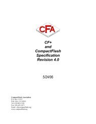
10. Documentation of CMASK bit range corrected<br />
In Figure 18-13 of the <strong>Intel</strong> ® <strong>64</strong> <strong>and</strong> <strong>IA</strong>-<strong>32</strong> <strong>Architectures</strong> <strong>Software</strong> Developer’s <strong>Manual</strong>,<br />
Volume 3B (in our new edition), the figure showing the layout of MSR <strong>IA</strong><strong>32</strong>PERFEVTSELx<br />
has been corrected to show the correct range of CMASK. The same change has been<br />
made to the paragraph text associated with the figure. See below.<br />
-------------------------------------------------------------------<br />
63<br />
31<br />
24 23 22 21 2019 18 17 16 15<br />
8 7 0<br />
Counter Mask<br />
(CMASK)<br />
I<br />
N<br />
V<br />
E<br />
N<br />
I<br />
N P<br />
T<br />
C<br />
E<br />
U<br />
O S<br />
S<br />
R<br />
Unit Mask (UMASK)<br />
Event Select<br />
INV—Invert counter mask<br />
EN—Enable counters<br />
INT—APIC interrupt enable<br />
PC—Pin control<br />
E—Edge detect<br />
OS—Operating system mode<br />
USR—User Mode<br />
Reserved<br />
Figure 18-13. Layout of <strong>IA</strong><strong>32</strong>_PERFEVTSELx MSRs<br />
.. ... ....Text omitted here... ... ....<br />
• Counter mask (CMASK) field (bits 24 through 31) — When this field is not zero,<br />
the logical processor compares this mask to the events count of the detected<br />
microarchitectural condition during a single cycle. If the event count is greater than<br />
or equal to this mask, the counter is incremented by one. Otherwise the counter is<br />
not incremented. This mask is intended for software to characterize microarchitectural<br />
conditions that can count multiple occurrences per cycle (for example, two or<br />
more instructions retired per clock; or bus queue occupations). If the counter-mask<br />
<strong>Intel</strong> ® <strong>64</strong> <strong>and</strong> <strong>IA</strong>-<strong>32</strong> <strong>Architectures</strong> <strong>Software</strong> Developer’s <strong>Manual</strong> Documentation Changes 19
Documentation Changes<br />
field is 0, then the counter is incremented each cycle by the event count associated<br />
with multiple occurrences.<br />
.. ... ....Text omitted here... ... ....<br />
11. Note defines additional restrictions on APIC DFR programming<br />
In Section 8.6.2.2 of the <strong>Intel</strong> ® <strong>64</strong> <strong>and</strong> <strong>IA</strong>-<strong>32</strong> <strong>Architectures</strong> <strong>Software</strong> Developer’s<br />
<strong>Manual</strong>, Volume 3A, the note has been updated to capture a programming<br />
recommendation. The note is reproduced below. See the change bars.<br />
------------------------------------------------------------------<br />
8.6.2.2 Logical Destination Mode<br />
.. ... ....Text omitted here... ... ....<br />
• The hierarchical cluster destination model can be used with Pentium 4, <strong>Intel</strong> Xeon, P6<br />
family, or Pentium processors. With this model, a hierarchical network can be<br />
created by connecting different flat clusters via independent system or APIC buses.<br />
This scheme requires a cluster manager within each cluster, which is responsible for<br />
h<strong>and</strong>ling message passing between system or APIC buses. One cluster contains up<br />
to 4 agents. Thus 15 cluster managers, each with 4 agents, can form a network of up<br />
to 60 APIC agents. Note that hierarchical APIC networks requires a special cluster<br />
manager device, which is not part of the local or the I/O APIC units.<br />
NOTE<br />
All processors that have their APIC software enabled (using the spurious<br />
vector enable/disable bit) must have their DFRs (Destination Format<br />
Registers) programmed identically.<br />
The default mode for DFR is flat mode. If you are using cluster mode,<br />
DFRs must be programmed before the APIC is software enabled. Since<br />
some chipsets do not accurately track a system view of the logical mode,<br />
program DFRs as soon as possible after starting the processor.<br />
8.6.2.3 Broadcast/Self Delivery Mode<br />
The destination shorth<strong>and</strong> field of the ICR allows the delivery mode to be by-passed in<br />
favor of broadcasting the IPI to all the processors on the system bus <strong>and</strong>/or back to itself<br />
(see Section 8.6.1, “Interrupt Comm<strong>and</strong> Register (ICR)”). Three destination shorth<strong>and</strong>s<br />
are supported: self, all excluding self, <strong>and</strong> all including self. The destination mode is<br />
ignored when a destination shorth<strong>and</strong> is used.<br />
... ....Text omitted here... ... ....<br />
12. Tables documenting MCA error codes updated<br />
Tables 14-15 <strong>and</strong> 14-16 in Section 14.7 of the <strong>Intel</strong> ® <strong>64</strong> <strong>and</strong> <strong>IA</strong>-<strong>32</strong> <strong>Architectures</strong><br />
<strong>Software</strong> Developer’s <strong>Manual</strong>, Volume 3A, have been updated. Information in the tables<br />
is grouped differently. See the change bars below.<br />
-------------------------------------------------------------------<br />
14.7. INTERPRETING THE MCA ERROR CODES<br />
When the processor detects a machine-check error condition, it writes a 16-bit error<br />
code to the MCA error code field of one of the <strong>IA</strong><strong>32</strong>_MCi_STATUS registers <strong>and</strong> sets the<br />
20 <strong>Intel</strong> ® <strong>64</strong> <strong>and</strong> <strong>IA</strong>-<strong>32</strong> <strong>Architectures</strong> <strong>Software</strong> Developer’s <strong>Manual</strong> Documentation Changes
Documentation Changes<br />
VAL (valid) flag in that register. The processor may also write a 16-bit model-specific<br />
error code in the <strong>IA</strong><strong>32</strong>_MCi_STATUS register depending on the implementation of the<br />
machine-check architecture of the processor.<br />
The MCA error codes are architecturally defined for <strong>IA</strong>-<strong>32</strong> processors. However, the<br />
specific <strong>IA</strong><strong>32</strong>_MCi_STATUS register that a code is ‘written to’ is model specific. To<br />
determine the cause of a machine-check exception, the machine-check exception<br />
h<strong>and</strong>ler must read the VAL flag for each <strong>IA</strong><strong>32</strong>_MCi_STATUS register. If the flag is set, the<br />
machine check-exception h<strong>and</strong>ler must then read the MCA error code field of the<br />
register. It is the encoding of the MCA error code field [15:0] that determines the type of<br />
error being reported <strong>and</strong> not the register bank reporting it.<br />
There are two types of MCA error codes: simple error codes <strong>and</strong> compound error codes.<br />
14.7.1 Simple Error Codes<br />
Table 14-15 shows the simple error codes. These unique codes indicate global error<br />
information.<br />
Table 14-15. <strong>IA</strong><strong>32</strong>_MCi_Status [15:0] Simple Error Code Encoding<br />
Error Code Binary Encoding Meaning<br />
No Error 0000 0000 0000 0000 No error has been reported to this bank of<br />
error-reporting registers.<br />
Unclassified 0000 0000 0000 0001 This error has not been classified into the<br />
MCA error classes.<br />
Microcode ROM 0000 0000 0000 0010 Parity error in internal microcode ROM<br />
Parity Error<br />
External Error 0000 0000 0000 0011 The BINIT# from another processor caused<br />
this processor to enter machine check. 1<br />
FRC Error 0000 0000 0000 0100 FRC (functional redundancy check) master/<br />
slave error<br />
Internal Timer Error 0000 0100 0000 0000 Internal timer error.<br />
Internal Unclassified 0000 01xx xxxx xxxx Internal unclassified errors. 2<br />
NOTES:<br />
1. BINIT# assertion will cause a machine check exception if the processor (or any processor on<br />
the same external bus) has BINIT# observation enabled during power-on configuration (hardware<br />
strapping) <strong>and</strong> if machine check exceptions are enabled (by setting CR4.MCE = 1).<br />
2. At least one X must equal one. Internal unclassified errors have not been classified. This is<br />
because no additional information is included in the machine check register.<br />
14.7.2 Compound Error Codes<br />
Compound error codes describe errors related to the TLBs, memory, caches, bus <strong>and</strong><br />
interconnect logic, <strong>and</strong> internal timer. A set of sub-fields is common to all of compound<br />
errors. These sub-fields describe the type of access, level in the memory hierarchy, <strong>and</strong><br />
type of request. Table 14-16 shows the general form of the compound error codes.<br />
<strong>Intel</strong> ® <strong>64</strong> <strong>and</strong> <strong>IA</strong>-<strong>32</strong> <strong>Architectures</strong> <strong>Software</strong> Developer’s <strong>Manual</strong> Documentation Changes 21
Documentation Changes<br />
Table 14-16. <strong>IA</strong><strong>32</strong>_MCi_Status [15:0] Compound Error Code Encoding<br />
Type Form Interpretation<br />
Generic Memory<br />
Hierarchy<br />
000F 0000 0000 11LL<br />
Generic memory hierarchy error<br />
TLB Errors 000F 0000 0001 TTLL {TT}TLB{LL}_ERR<br />
Memory Hierarchy Errors 000F 0001 RRRR TTLL {TT}CACHE{LL}_{RRRR}_ERR<br />
Bus <strong>and</strong> Interconnect<br />
Errors<br />
000F 1PPT RRRR IILL<br />
BUS{LL}_{PP}_{RRRR}_{II}_{T}_ERR<br />
The “Interpretation” column in the table indicates the name of a compound error. The<br />
name is constructed by substituting mnemonics for the sub-field names given within<br />
curly braces. For example, the error code ICACHEL1_RD_ERR is constructed from the<br />
form:<br />
{TT}CACHE{LL}_{RRRR}_ERR,<br />
where {TT} is replaced by I, {LL} is replaced by L1, <strong>and</strong> {RRRR} is replaced by RD.<br />
For more information on the “Form” <strong>and</strong> “Interpretation” columns, see Section 14.7.2.1,<br />
“Correction Report Filtering (F) Bit” through Section 14.7.2.5, “Bus <strong>and</strong> Interconnect<br />
Errors”.<br />
.. ... ....Text omitted here... ... ....<br />
13. PUSHA/PUSHAD information updated<br />
In the Description subsection, “PUSHA/PUSHAD—Push All General-Purpose Registers”, in<br />
Chapter 4 of the <strong>Intel</strong> ® <strong>64</strong> <strong>and</strong> <strong>IA</strong>-<strong>32</strong> <strong>Architectures</strong> <strong>Software</strong> Developer’s <strong>Manual</strong>,<br />
Volume 2B, the language has been updated to correct an error (EBP was listed twice in<br />
the earlier version). See the change bar <strong>and</strong> bold text.<br />
-------------------------------------------------------------------<br />
PUSHA/PUSHAD—Push All General-Purpose Registers<br />
Opcode Instruction <strong>64</strong>-Bit<br />
Mode<br />
Compat/<br />
Leg Mode<br />
Description<br />
60 PUSHA Invalid Valid Push AX, CX, DX, BX, original SP, BP, SI,<br />
<strong>and</strong> DI.<br />
60 PUSHAD Invalid Valid Push EAX, ECX, EDX, EBX, original ESP,<br />
EBP, ESI, <strong>and</strong> EDI.<br />
Description<br />
Pushes the contents of the general-purpose registers onto the stack. The registers are<br />
stored on the stack in the following order: EAX, ECX, EDX, EBX, ESP (original<br />
value), EBP, ESI, <strong>and</strong> EDI (if the current oper<strong>and</strong>-size attribute is <strong>32</strong>) <strong>and</strong> AX,<br />
CX, DX, BX, SP (original value), BP, SI, <strong>and</strong> DI (if the oper<strong>and</strong>-size attribute is<br />
16). These instructions perform the reverse operation of the POPA/POPAD instructions.<br />
The value pushed for the ESP or SP register is its value before prior to pushing the first<br />
register (see the “Operation” section below).<br />
The PUSHA (push all) <strong>and</strong> PUSHAD (push all double) mnemonics reference the same<br />
opcode. The PUSHA instruction is intended for use when the oper<strong>and</strong>-size attribute is 16<br />
<strong>and</strong> the PUSHAD instruction for when the oper<strong>and</strong>-size attribute is <strong>32</strong>. Some assemblers<br />
may force the oper<strong>and</strong> size to 16 when PUSHA is used <strong>and</strong> to <strong>32</strong> when PUSHAD is used.<br />
22 <strong>Intel</strong> ® <strong>64</strong> <strong>and</strong> <strong>IA</strong>-<strong>32</strong> <strong>Architectures</strong> <strong>Software</strong> Developer’s <strong>Manual</strong> Documentation Changes
Documentation Changes<br />
Others may treat these mnemonics as synonyms (PUSHA/PUSHAD) <strong>and</strong> use the current<br />
setting of the oper<strong>and</strong>-size attribute to determine the size of values to be pushed from<br />
the stack, regardless of the mnemonic used.<br />
In the real-address mode, if the ESP or SP register is 1, 3, or 5 when PUSHA/PUSHAD<br />
executes: an #SS exception is generated but not delivered (the stack error reported<br />
prevents #SS delivery). Next, the processor generates a #DF exception <strong>and</strong> enters a<br />
shutdown state as described in the #DF discussion in Chapter 5 of the <strong>Intel</strong> ® <strong>64</strong> <strong>and</strong><br />
<strong>IA</strong>-<strong>32</strong> <strong>Architectures</strong> <strong>Software</strong> Developer’s <strong>Manual</strong>, Volume 3A.<br />
This instruction executes as described in compatibility mode <strong>and</strong> legacy mode. It is not<br />
valid in <strong>64</strong>-bit mode.<br />
.. ... ....Text omitted here... ... ....<br />
14. VMCALL pseudocode updated<br />
In the Operations subsection, “VMCALL—Call to VM Monitor”, in Chapter 5 of the <strong>Intel</strong> ®<br />
<strong>64</strong> <strong>and</strong> <strong>IA</strong>-<strong>32</strong> <strong>Architectures</strong> <strong>Software</strong> Developer’s <strong>Manual</strong>, Volume 3B, the pseudocode<br />
has been updated. The change accommodates an architectural decision made pertaining<br />
to the h<strong>and</strong>ling of SMM.<br />
The subsection is reprinted below. See the change bars.<br />
-------------------------------------------------------------------<br />
Operation<br />
IF not in VMX operation<br />
THEN #UD;<br />
ELSIF in VMX non-root operation<br />
THEN VM exit;<br />
ELSIF in SMM or if the valid bit in the <strong>IA</strong><strong>32</strong>_SMM_MONITOR_CTL MSR is clear<br />
THEN VMfail(VMCALL executed in VMX root operation);<br />
ELSIF (RFLAGS.VM = 1) OR (<strong>IA</strong><strong>32</strong>_EFER.LMA = 1 <strong>and</strong> CS.L = 0)<br />
THEN #UD;<br />
ELSIF CPL > 0<br />
THEN #GP(0);<br />
ELSIF dual-monitor treatment of SMIs <strong>and</strong> SMM is active<br />
THEN perform an SMM VM exit (see Section 24.16.2<br />
of the <strong>Intel</strong> ® <strong>64</strong> <strong>and</strong> <strong>IA</strong>-<strong>32</strong> <strong>Architectures</strong> <strong>Software</strong> Developer’s <strong>Manual</strong>, Volume 3B);<br />
ELSIF current-VMCS pointer is not valid<br />
THEN VMfailInvalid;<br />
ELSIF launch state of current VMCS is not clear<br />
THEN VMfailValid(VMCALL with non-clear VMCS);<br />
ELSIF VM-exit control fields are not valid (see Section 24.16.6.1 of the <strong>Intel</strong> ® <strong>64</strong> <strong>and</strong> <strong>IA</strong>-<strong>32</strong> <strong>Architectures</strong><br />
<strong>Software</strong> Developer’s <strong>Manual</strong>, Volume 3B)<br />
THEN VMfailValid(VMCALL with invalid VM-exit control fields);<br />
ELSE<br />
enter SMM;<br />
read revision identifier in MSEG;<br />
IF revision identifier does not match that supported by processor<br />
THEN<br />
leave SMM;<br />
VMfailValid(VMCALL with incorrect MSEG revision identifier);<br />
ELSE<br />
<strong>Intel</strong> ® <strong>64</strong> <strong>and</strong> <strong>IA</strong>-<strong>32</strong> <strong>Architectures</strong> <strong>Software</strong> Developer’s <strong>Manual</strong> Documentation Changes 23
Documentation Changes<br />
FI;<br />
FI;<br />
read SMM-monitor features field in MSEG (see Section 24.16.6.2,<br />
in the <strong>Intel</strong> ® <strong>64</strong> <strong>and</strong> <strong>IA</strong>-<strong>32</strong> <strong>Architectures</strong> <strong>Software</strong> Developer’s <strong>Manual</strong>, Volume 3B);<br />
IF features field is invalid<br />
THEN<br />
leave SMM;<br />
VMfailValid(VMCALL with invalid SMM-monitor features);<br />
ELSE activate dual-monitor treatment of SMIs <strong>and</strong> SMM (see Section 24.16.6<br />
in the <strong>Intel</strong> ® <strong>64</strong> <strong>and</strong> <strong>IA</strong>-<strong>32</strong> <strong>Architectures</strong> <strong>Software</strong> Developer’s <strong>Manual</strong>, Volume 3B);<br />
FI;<br />
15. Information on code fetches in uncacheable memory updated<br />
In Section 10.3.3 of the <strong>Intel</strong> ® <strong>64</strong> <strong>and</strong> <strong>IA</strong>-<strong>32</strong> <strong>Architectures</strong> <strong>Software</strong> Developer’s <strong>Manual</strong>,<br />
Volume 3A, the language has been updated to address confusion.<br />
The section is reproduced below.<br />
-------------------------------------------------------------------<br />
10.3.3 Code Fetches in Uncacheable Memory<br />
Programs may execute code from uncacheable (UC) memory, but the implications are<br />
different from accessing data in UC memory. When doing code fetches, the processor<br />
never transitions from cacheable code to UC code speculatively. It also never<br />
speculatively fetches branch targets that result in UC code.<br />
The processor may fetch the same UC cache line multiple times in order to decode an<br />
instruction once. It may decode consecutive UC instructions in a cacheline without<br />
fetching between each instruction. It may also fetch additional cachelines from the same<br />
or a consecutive 4-KByte page in order to decode one non-speculative UC instruction<br />
(this can be true even when the instruction is contained fully in one line).<br />
Because of the above <strong>and</strong> because cacheline sizes may change in future processors,<br />
software should avoid placing memory-mapped I/O with read side effects in the same<br />
page or in a subsequent page used to execute UC code.<br />
16. PUSH description updated<br />
In the Description subsection, “PUSH—Push Word, Doubleword or Quadword Onto the<br />
Stack”, in Chapter 4 of the <strong>Intel</strong> ® <strong>64</strong> <strong>and</strong> <strong>IA</strong>-<strong>32</strong> <strong>Architectures</strong> <strong>Software</strong> Developer’s<br />
<strong>Manual</strong>, Volume 2B, the language describing the instructions in real-address mode has<br />
been corrected.<br />
The subsection is reprinted below. See the change bar.<br />
------------------------------------------------------------------<br />
Description<br />
Decrements the stack pointer <strong>and</strong> then stores the source oper<strong>and</strong> on the top of the<br />
stack. The address-size attribute of the stack segment determines the stack pointer size<br />
(16, <strong>32</strong> or <strong>64</strong> bits). The oper<strong>and</strong>-size attribute of the current code segment determines<br />
the amount the stack pointer is decremented (2, 4 or 8 bytes).<br />
In non-<strong>64</strong>-bit modes: if the address-size <strong>and</strong> oper<strong>and</strong>-size attributes are <strong>32</strong>, the <strong>32</strong>-bit<br />
ESP register (stack pointer) is decremented by 4. If both attributes are 16, the 16-bit SP<br />
register (stack pointer) is decremented by 2.<br />
24 <strong>Intel</strong> ® <strong>64</strong> <strong>and</strong> <strong>IA</strong>-<strong>32</strong> <strong>Architectures</strong> <strong>Software</strong> Developer’s <strong>Manual</strong> Documentation Changes
Documentation Changes<br />
If the source oper<strong>and</strong> is an immediate <strong>and</strong> its size is less than the address size of the<br />
stack, a sign-extended value is pushed on the stack. If the source oper<strong>and</strong> is the FS or<br />
GS <strong>and</strong> its size is less than the address size of the stack, the zero-extended value is<br />
pushed on the stack.<br />
The B flag in the stack segment’s segment descriptor determines the stack’s addresssize<br />
attribute. The D flag in the current code segment’s segment descriptor (with<br />
prefixes), determines the oper<strong>and</strong>-size attribute <strong>and</strong> the address-size attribute of the<br />
source oper<strong>and</strong>. Pushing a 16-bit oper<strong>and</strong> when the stack address-size attribute is <strong>32</strong><br />
can result in a misaligned stack pointer (a stack pointer that is not be aligned on a<br />
doubleword boundary).<br />
The PUSH ESP instruction pushes the value of the ESP register as it existed before the<br />
instruction was executed. Thus if a PUSH instruction uses a memory oper<strong>and</strong> in which<br />
the ESP register is used for computing the oper<strong>and</strong> address, the address of the oper<strong>and</strong><br />
is computed before the ESP register is decremented.<br />
In the real-address mode, if the ESP or SP register is 1 when the PUSH instruction is<br />
executed, an #SS exception is generated but not delivered (the stack error reported<br />
prevents #SS delivery). Next, the processor generates a #DF exception <strong>and</strong> enters a<br />
shutdown state as described in the #DF discussion in Chapter 5 of the <strong>Intel</strong> ® <strong>64</strong> <strong>and</strong><br />
<strong>IA</strong>-<strong>32</strong> <strong>Architectures</strong> <strong>Software</strong> Developer’s <strong>Manual</strong>, Volume 3A.<br />
In <strong>64</strong>-bit mode, the instruction’s default operation size is <strong>64</strong> bits. In a push, the <strong>64</strong>-bit<br />
RSP register (stack pointer) is decremented by 8. A 66H override causes 16-bit<br />
operation. Note that pushing a 16-bit oper<strong>and</strong> can result in the stack pointer misaligned<br />
to 8-byte boundary.<br />
.. ... ....Text omitted here... ... ....<br />
17. IRET/IRETD pseudocode updated<br />
In the Operation subsection, “IRET/IRETD—Interrupt Return”, in Chapter 3 of the <strong>Intel</strong> ®<br />
<strong>64</strong> <strong>and</strong> <strong>IA</strong>-<strong>32</strong> <strong>Architectures</strong> <strong>Software</strong> Developer’s <strong>Manual</strong>, Volume 2A, the pseudocode<br />
has been updated to correct an error.<br />
The subsection is reprinted below. See the change bar.<br />
-------------------------------------------------------------------<br />
Operation<br />
IF PE = 0<br />
THEN<br />
GOTO REAL-ADDRESS-MODE;<br />
ELSE<br />
IF (<strong>IA</strong><strong>32</strong>_EFER.LMA = 0)<br />
THEN (* Protected mode *)<br />
GOTO PROTECTED-MODE;<br />
ELSE (* <strong>IA</strong>-<strong>32</strong>e mode *)<br />
GOTO <strong>IA</strong>-<strong>32</strong>e-MODE;<br />
FI;<br />
FI;<br />
REAL-ADDRESS-MODE;<br />
IF Oper<strong>and</strong>Size = <strong>32</strong><br />
THEN<br />
IF top 12 bytes of stack not within stack limits<br />
THEN #SS; FI;<br />
tempEIP ← 4 bytes at end of stack<br />
<strong>Intel</strong> ® <strong>64</strong> <strong>and</strong> <strong>IA</strong>-<strong>32</strong> <strong>Architectures</strong> <strong>Software</strong> Developer’s <strong>Manual</strong> Documentation Changes 25
Documentation Changes<br />
IF tempEIP[31:16] is not zero THEN #GP(0); FI;<br />
EIP ← Pop();<br />
CS ← Pop(); (* <strong>32</strong>-bit pop, high-order 16 bits discarded *)<br />
tempEFLAGS ← Pop();<br />
EFLAGS ← (tempEFLAGS AND 257FD5H) OR (EFLAGS AND 1A0000H);<br />
ELSE (* Oper<strong>and</strong>Size = 16 *)<br />
IF top 6 bytes of stack are not within stack limits<br />
THEN #SS; FI;<br />
EIP ← Pop(); (* 16-bit pop; clear upper 16 bits *)<br />
CS ← Pop(); (* 16-bit pop *)<br />
EFLAGS[15:0] ← Pop();<br />
FI;<br />
END;<br />
PROTECTED-MODE:<br />
IF VM = 1 (* Virtual-8086 mode: PE = 1, VM = 1 *)<br />
THEN<br />
GOTO RETURN-FROM-VIRTUAL-8086-MODE; (* PE = 1, VM = 1 *)<br />
FI;<br />
IF NT = 1<br />
THEN<br />
GOTO TASK-RETURN; (* PE = 1, VM = 0, NT = 1 *)<br />
FI;<br />
IF Oper<strong>and</strong>Size = <strong>32</strong><br />
THEN<br />
IF top 12 bytes of stack not within stack limits<br />
THEN #SS(0); FI;<br />
tempEIP ← Pop();<br />
tempCS ← Pop();<br />
tempEFLAGS ← Pop();<br />
ELSE (* Oper<strong>and</strong>Size = 16 *)<br />
IF top 6 bytes of stack are not within stack limits<br />
THEN #SS(0); FI;<br />
tempEIP ← Pop();<br />
tempCS ← Pop();<br />
tempEFLAGS ← Pop();<br />
tempEIP ← tempEIP AND FFFFH;<br />
tempEFLAGS ← tempEFLAGS AND FFFFH;<br />
FI;<br />
IF tempEFLAGS(VM) = 1 <strong>and</strong> CPL = 0<br />
THEN<br />
GOTO RETURN-TO-VIRTUAL-8086-MODE;<br />
(* PE = 1, VM = 1 in EFLAGS image *)<br />
ELSE<br />
GOTO PROTECTED-MODE-RETURN;<br />
(* PE = 1, VM = 0 in EFLAGS image *)<br />
FI;<br />
<strong>IA</strong>-<strong>32</strong>e-MODE:<br />
IF NT = 1<br />
THEN #GP(0);<br />
ELSE IF Oper<strong>and</strong>Size = <strong>32</strong><br />
THEN<br />
IF top 12 bytes of stack not within stack limits<br />
26 <strong>Intel</strong> ® <strong>64</strong> <strong>and</strong> <strong>IA</strong>-<strong>32</strong> <strong>Architectures</strong> <strong>Software</strong> Developer’s <strong>Manual</strong> Documentation Changes
Documentation Changes<br />
THEN #SS(0); FI;<br />
tempEIP ← Pop();<br />
tempCS ← Pop();<br />
tempEFLAGS ← Pop();<br />
ELSE IF Oper<strong>and</strong>Size = 16<br />
THEN<br />
IF top 6 bytes of stack are not within stack limits<br />
THEN #SS(0); FI;<br />
tempEIP ← Pop();<br />
tempCS ← Pop();<br />
tempEFLAGS ← Pop();<br />
tempEIP ← tempEIP AND FFFFH;<br />
tempEFLAGS ← tempEFLAGS AND FFFFH;<br />
FI;<br />
ELSE (* Oper<strong>and</strong>Size = <strong>64</strong> *)<br />
THEN<br />
tempRIP ← Pop();<br />
tempCS ← Pop();<br />
tempEFLAGS ← Pop();<br />
tempRSP ← Pop();<br />
tempSS ← Pop();<br />
FI;<br />
GOTO <strong>IA</strong>-<strong>32</strong>e-MODE-RETURN;<br />
RETURN-FROM-VIRTUAL-8086-MODE:<br />
(* Processor is in virtual-8086 mode when IRET is executed <strong>and</strong> stays in virtual-8086 mode *)<br />
IF IOPL = 3 (* Virtual mode: PE = 1, VM = 1, IOPL = 3 *)<br />
THEN IF Oper<strong>and</strong>Size = <strong>32</strong><br />
THEN<br />
IF top 12 bytes of stack not within stack limits<br />
THEN #SS(0); FI;<br />
IF instruction pointer not within code segment limits<br />
THEN #GP(0); FI;<br />
EIP ← Pop();<br />
CS ← Pop(); (* <strong>32</strong>-bit pop, high-order 16 bits discarded *)<br />
EFLAGS ← Pop();<br />
(* VM, IOPL,VIP <strong>and</strong> VIF EFLAG bits not modified by pop *)<br />
ELSE (* Oper<strong>and</strong>Size = 16 *)<br />
IF top 6 bytes of stack are not within stack limits<br />
THEN #SS(0); FI;<br />
IF instruction pointer not within code segment limits<br />
THEN #GP(0); FI;<br />
EIP ← Pop();<br />
EIP ← EIP AND 0000FFFFH;<br />
CS ← Pop(); (* 16-bit pop *)<br />
EFLAGS[15:0] ← Pop(); (* IOPL in EFLAGS not modified by pop *)<br />
FI;<br />
ELSE<br />
#GP(0); (* Trap to virtual-8086 monitor: PE = 1, VM = 1, IOPL < 3 *)<br />
FI;<br />
END;<br />
<strong>Intel</strong> ® <strong>64</strong> <strong>and</strong> <strong>IA</strong>-<strong>32</strong> <strong>Architectures</strong> <strong>Software</strong> Developer’s <strong>Manual</strong> Documentation Changes 27
Documentation Changes<br />
RETURN-TO-VIRTUAL-8086-MODE:<br />
(* Interrupted procedure was in virtual-8086 mode: PE = 1, VM = 1 in flag image *)<br />
IF top 24 bytes of stack are not within stack segment limits<br />
THEN #SS(0); FI;<br />
IF instruction pointer not within code segment limits<br />
THEN #GP(0); FI;<br />
CS ← tempCS;<br />
EIP ← tempEIP;<br />
EFLAGS ← tempEFLAGS;<br />
TempESP ← Pop();<br />
TempSS ← Pop();<br />
ES ← Pop(); (* Pop 2 words; throw away high-order word *)<br />
DS ← Pop(); (* Pop 2 words; throw away high-order word *)<br />
FS ← Pop(); (* Pop 2 words; throw away high-order word *)<br />
GS ← Pop(); (* Pop 2 words; throw away high-order word *)<br />
SS:ESP ← TempSS:TempESP;<br />
CPL ← 3;<br />
(* Resume execution in Virtual-8086 mode *)<br />
END;<br />
TASK-RETURN: (* PE = 1, VM = 0, NT = 1 *)<br />
Read segment selector in link field of current TSS;<br />
IF local/global bit is set to local<br />
or index not within GDT limits<br />
THEN #TS (TSS selector); FI;<br />
Access TSS for task specified in link field of current TSS;<br />
IF TSS descriptor type is not TSS or if the TSS is marked not busy<br />
THEN #TS (TSS selector); FI;<br />
IF TSS not present<br />
THEN #NP(TSS selector); FI;<br />
SWITCH-TASKS (without nesting) to TSS specified in link field of current TSS;<br />
Mark the task just ab<strong>and</strong>oned as NOT BUSY;<br />
IF EIP is not within code segment limit<br />
THEN #GP(0); FI;<br />
END;<br />
PROTECTED-MODE-RETURN: (* PE = 1, VM = 0 in flags image *)<br />
IF return code segment selector is NULL<br />
THEN GP(0); FI;<br />
IF return code segment selector addrsses descriptor beyond descriptor table limit<br />
THEN GP(selector); FI;<br />
Read segment descriptor pointed to by the return code segment selector;<br />
IF return code segment descriptor is not a code segment<br />
THEN #GP(selector); FI;<br />
IF return code segment selector RPL < CPL<br />
THEN #GP(selector); FI;<br />
IF return code segment descriptor is conforming<br />
<strong>and</strong> return code segment DPL > return code segment selector RPL<br />
THEN #GP(selector); FI;<br />
IF return code segment descriptor is not present<br />
THEN #NP(selector); FI;<br />
IF return code segment selector RPL > CPL<br />
28 <strong>Intel</strong> ® <strong>64</strong> <strong>and</strong> <strong>IA</strong>-<strong>32</strong> <strong>Architectures</strong> <strong>Software</strong> Developer’s <strong>Manual</strong> Documentation Changes
Documentation Changes<br />
END;<br />
THEN GOTO RETURN-OUTER-PRIVILEGE-LEVEL;<br />
ELSE GOTO RETURN-TO-SAME-PRIVILEGE-LEVEL; FI;<br />
RETURN-TO-SAME-PRIVILEGE-LEVEL: (* PE = 1, VM = 0 in flags image, RPL = CPL *)<br />
IF new mode ≠ <strong>64</strong>-Bit Mode<br />
THEN<br />
IF tempEIP is not within code segment limits<br />
THEN #GP(0); FI;<br />
EIP ← tempEIP;<br />
ELSE (* new mode = <strong>64</strong>-bit mode *)<br />
IF tempRIP is non-canonical<br />
THEN #GP(0); FI;<br />
RIP ← tempRIP;<br />
FI;<br />
CS ← tempCS; (* Segment descriptor information also loaded *)<br />
EFLAGS (CF, PF, AF, ZF, SF, TF, DF, OF, NT) ← tempEFLAGS;<br />
IF Oper<strong>and</strong>Size = <strong>32</strong> or Oper<strong>and</strong>Size = <strong>64</strong><br />
THEN EFLAGS(RF, AC, ID) ← tempEFLAGS; FI;<br />
IF CPL ≤ IOPL<br />
THEN EFLAGS(IF) ← tempEFLAGS; FI;<br />
IF CPL = 0<br />
THEN EFLAGS(IOPL) ← tempEFLAGS;<br />
IF Oper<strong>and</strong>Size = <strong>32</strong><br />
THEN EFLAGS(VM, VIF, VIP) ← tempEFLAGS; FI;<br />
IF Oper<strong>and</strong>Size = <strong>64</strong><br />
THEN EFLAGS( VIF, VIP) ← tempEFLAGS; FI;<br />
FI;<br />
END;<br />
RETURN-TO-OUTER-PRIVILEGE-LEVEL:<br />
IF Oper<strong>and</strong>Size = <strong>32</strong><br />
THEN<br />
IF top 8 bytes on stack are not within limits<br />
THEN #SS(0); FI;<br />
ELSE (* Oper<strong>and</strong>Size = 16 *)<br />
IF top 4 bytes on stack are not within limits<br />
THEN #SS(0); FI;<br />
FI;<br />
Read return segment selector;<br />
IF stack segment selector is NULL<br />
THEN #GP(0); FI;<br />
IF return stack segment selector index is not within its descriptor table limits<br />
THEN #GP(SSselector); FI;<br />
Read segment descriptor pointed to by return segment selector;<br />
IF stack segment selector RPL ≠ RPL of the return code segment selector<br />
or the stack segment descriptor does not indicate a a writable data segment;<br />
or the stack segment DPL ≠ RPL of the return code segment selector<br />
THEN #GP(SS selector); FI;<br />
IF stack segment is not present<br />
THEN #SS(SS selector); FI;<br />
IF new mode ≠ <strong>64</strong>-Bit Mode<br />
<strong>Intel</strong> ® <strong>64</strong> <strong>and</strong> <strong>IA</strong>-<strong>32</strong> <strong>Architectures</strong> <strong>Software</strong> Developer’s <strong>Manual</strong> Documentation Changes 29
Documentation Changes<br />
THEN<br />
IF tempEIP is not within code segment limits<br />
THEN #GP(0); FI;<br />
EIP ← tempEIP;<br />
ELSE (* new mode = <strong>64</strong>-bit mode *)<br />
IF tempRIP is non-canonical<br />
THEN #GP(0); FI;<br />
RIP ← tempRIP;<br />
FI;<br />
CS ← tempCS;<br />
EFLAGS (CF, PF, AF, ZF, SF, TF, DF, OF, NT) ← tempEFLAGS;<br />
IF Oper<strong>and</strong>Size = <strong>32</strong><br />
THEN EFLAGS(RF, AC, ID) ← tempEFLAGS; FI;<br />
IF CPL ≤ IOPL<br />
THEN EFLAGS(IF) ← tempEFLAGS; FI;<br />
IF CPL = 0<br />
THEN<br />
EFLAGS(IOPL) ← tempEFLAGS;<br />
IF Oper<strong>and</strong>Size = <strong>32</strong><br />
THEN EFLAGS(VM, VIF, VIP) ← tempEFLAGS; FI;<br />
IF Oper<strong>and</strong>Size = <strong>64</strong><br />
THEN EFLAGS( VIF, VIP) ← tempEFLAGS; FI;<br />
FI;<br />
CPL ← RPL of the return code segment selector;<br />
FOR each of segment register (ES, FS, GS, <strong>and</strong> DS)<br />
DO<br />
IF segment register points to data or non-conforming code segment<br />
<strong>and</strong> CPL > segment descriptor DPL (* Stored in hidden part of segment register *)<br />
THEN (* Segment register invalid *)<br />
SegmentSelector ← 0; (* NULL segment selector *)<br />
FI;<br />
OD;<br />
END;<br />
<strong>IA</strong>-<strong>32</strong>e-MODE-RETURN: (* <strong>IA</strong><strong>32</strong>_EFER.LMA = 1, PE = 1, VM = 0 in flags image *)<br />
IF ( (return code segment selector is NULL) or (return RIP is non-canonical) or<br />
(SS selector is NULL going back to compatibility mode) or<br />
(SS selector is NULL going back to CPL3 <strong>64</strong>-bit mode) or<br />
(RPL CPL going back to non-CPL3 <strong>64</strong>-bit mode for a NULL SS selector) )<br />
THEN GP(0); FI;<br />
IF return code segment selector addrsses descriptor beyond descriptor table limit<br />
THEN GP(selector); FI;<br />
Read segment descriptor pointed to by the return code segment selector;<br />
IF return code segment descriptor is not a code segment<br />
THEN #GP(selector); FI;<br />
IF return code segment selector RPL < CPL<br />
THEN #GP(selector); FI;<br />
IF return code segment descriptor is conforming<br />
<strong>and</strong> return code segment DPL > return code segment selector RPL<br />
THEN #GP(selector); FI;<br />
IF return code segment descriptor is not present<br />
THEN #NP(selector); FI;<br />
IF return code segment selector RPL > CPL<br />
30 <strong>Intel</strong> ® <strong>64</strong> <strong>and</strong> <strong>IA</strong>-<strong>32</strong> <strong>Architectures</strong> <strong>Software</strong> Developer’s <strong>Manual</strong> Documentation Changes
Documentation Changes<br />
END;<br />
THEN GOTO RETURN-OUTER-PRIVILEGE-LEVEL;<br />
ELSE GOTO RETURN-TO-SAME-PRIVILEGE-LEVEL; FI;<br />
18. BSR summary table updated<br />
In Chapter 3, “BSR—Bit Scan Reverse”, of the <strong>Intel</strong> ® <strong>64</strong> <strong>and</strong> <strong>IA</strong>-<strong>32</strong> <strong>Architectures</strong><br />
<strong>Software</strong> Developer’s <strong>Manual</strong>, Volume 2A, the summary table has been updated (/r was<br />
added). See the change bar below.<br />
-------------------------------------------------------------------<br />
BSR—Bit Scan Reverse<br />
Opcode Instruction <strong>64</strong>-Bit<br />
Mode<br />
Compat/<br />
Leg Mode<br />
Description<br />
0F BD /r BSR r16, r/m16 Valid Valid Bit scan reverse on r/m16.<br />
0F BD /r BSR r<strong>32</strong>, r/m<strong>32</strong> Valid Valid Bit scan reverse on r/m<strong>32</strong>.<br />
REX.W + 0F BD BSR r<strong>64</strong>, r/m<strong>64</strong> Valid N.E. Bit scan reverse on r/m<strong>64</strong>.<br />
19. SYSCALL <strong>and</strong> SYSRET pseudocode updated<br />
In Chapter 4, “SYSCALL—Fast System Call” <strong>and</strong> “SYSRET—Return From Fast System<br />
Call” of the <strong>Intel</strong> ® <strong>64</strong> <strong>and</strong> <strong>IA</strong>-<strong>32</strong> <strong>Architectures</strong> <strong>Software</strong> Developer’s <strong>Manual</strong>, Volume 2B,<br />
the pseudocode has been corrected.<br />
See the change bars on the reprinted subsections below.<br />
-------------------------------------------------------------------<br />
SYSCALL—Fast System Call<br />
Operation<br />
IF ((CS.L ) or (<strong>IA</strong><strong>32</strong>_EFER.LMA ≠ 1) or (<strong>IA</strong><strong>32</strong>_EFER.SCE ≠ 1))<br />
(* Not in <strong>64</strong>-Bit Mode or SYSCALL/SYSRET not enabled in <strong>IA</strong><strong>32</strong>_EFER *)<br />
THEN #UD; FI;<br />
RCX ← RIP;<br />
RIP ← LSTAR_MSR;<br />
R11 ← EFLAGS;<br />
EFLAGS ← (EFLAGS MASKED BY <strong>IA</strong><strong>32</strong>_FMASK);<br />
CPL ← 0;<br />
CS(SEL) ← <strong>IA</strong><strong>32</strong>_STAR_MSR[47:<strong>32</strong>];<br />
CS(DPL) ← 0;<br />
CS(BASE) ← 0;<br />
CS(LIMIT) ← 0xFFFFF;<br />
CS(GRANULAR) ← 1;<br />
SS(SEL) ← <strong>IA</strong><strong>32</strong>_STAR_MSR[47:<strong>32</strong>] + 8;<br />
SS(DPL) ← 0;<br />
SS(BASE) ← 0;<br />
SS(LIMIT) ← 0xFFFFF;<br />
SS(GRANULAR) ← 1;<br />
<strong>Intel</strong> ® <strong>64</strong> <strong>and</strong> <strong>IA</strong>-<strong>32</strong> <strong>Architectures</strong> <strong>Software</strong> Developer’s <strong>Manual</strong> Documentation Changes 31
Documentation Changes<br />
SYSRET—Return From Fast System Call<br />
... .... ... ... Not all text shown... ... ...<br />
Operation<br />
IF (CS.L ≠ 1 ) or (<strong>IA</strong><strong>32</strong>_EFER.LMA ≠ 1) or (<strong>IA</strong><strong>32</strong>_EFER.SCE ≠ 1)<br />
(* Not in <strong>64</strong>-Bit Mode or SYSCALL/SYSRET not enabled in <strong>IA</strong><strong>32</strong>_EFER *)<br />
THEN #UD; FI;<br />
IF (CPL ≠ 0)<br />
THEN #GP(0); FI;<br />
IF (RCX ≠ CANONICAL_ADDRESS)<br />
THEN #GP(0); FI;<br />
IF (OPERAND_SIZE = <strong>64</strong>)<br />
THEN (* Return to <strong>64</strong>-Bit Mode *)<br />
EFLAGS ← R11;<br />
CPL ← 0x3;<br />
CS(SEL) ← <strong>IA</strong><strong>32</strong>_STAR[63:48] + 16;<br />
CS(PL) ← 0x3;<br />
SS(SEL) ← <strong>IA</strong><strong>32</strong>_STAR[63:48] + 8;<br />
SS(PL) ← 0x3;<br />
RIP ← RCX;<br />
ELSE (* Return to Compatibility Mode *)<br />
EFLAGS ← R11;<br />
CPL ← 0x3;<br />
CS(SEL) ← <strong>IA</strong><strong>32</strong>_STAR[63:48] ;<br />
CS(PL) ← 0x3;<br />
SS(SEL) ← <strong>IA</strong><strong>32</strong>_STAR[63:48] + 8;<br />
SS(PL) ← 0x3;<br />
EIP ← ECX;<br />
FI;<br />
20. VMX Debug exceptions paragraph deleted<br />
In Section 27.3.1 of the <strong>Intel</strong> ® <strong>64</strong> <strong>and</strong> <strong>IA</strong>-<strong>32</strong> <strong>Architectures</strong> <strong>Software</strong> Developer’s <strong>Manual</strong>,<br />
Volume 3B, the first two paragraphs were deleted.<br />
-------------------------------------------------------------------<br />
27.3.1 Debug Exceptions<br />
If a VMM emulates a guest instruction that would encounter a debug trap (single step or<br />
data or I/O breakpoint), it should cause that trap to be delivered. The VMM should not<br />
inject the debug exception by using vector-on-entry, but should set the appropriate bits<br />
in the pending debug exceptions field. This method will give the trap the right priority<br />
with respect to other events. (If the exception bitmap was programmed to cause VM<br />
exits on debug exceptions, the debug trap will cause a VM exit. At this point, the trap can<br />
be injected with vector-on-entry with the proper priority.)<br />
There is a valid pending debug exception if the BS bit (see Table 20-4) is set, regardless<br />
of the values of RFLAGS.TF or <strong>IA</strong><strong>32</strong>_DEBUGCTL.BTF. The values of these bits do not<br />
impact the delivery of pending debug exceptions.<br />
<strong>32</strong> <strong>Intel</strong> ® <strong>64</strong> <strong>and</strong> <strong>IA</strong>-<strong>32</strong> <strong>Architectures</strong> <strong>Software</strong> Developer’s <strong>Manual</strong> Documentation Changes
Documentation Changes<br />
VMMs should exercise care when emulating a guest write (attempted using WRMSR) to<br />
<strong>IA</strong><strong>32</strong>_DEBUGCTL to modify BTF if this is occurring with RFLAGS.TF = 1 <strong>and</strong> after a MOV<br />
SS or POP SS instruction (for example: while debug exceptions are blocked). Note the<br />
following:<br />
• Normally, if WRMSR clears BTF while RFLAGS.TF = 1 <strong>and</strong> with debug exceptions<br />
blocked, a single-step trap will occur after WRMSR. A VMM emulating such an<br />
instruction should set the BS bit (see Table 20-4) in the pending debug exceptions<br />
field before VM entry.<br />
• Normally, if WRMSR sets BTF while RFLAGS.TF = 1 <strong>and</strong> with debug exceptions<br />
blocked, neither a single-step trap nor a taken-branch trap can occur after WRMSR.<br />
A VMM emulating such an instruction should clear the BS bit (see Table 20-4) in the<br />
pending debug exceptions field before VM entry.<br />
.. ... ....Text omitted here... ... ....<br />
21. FLD list of exceptions updated<br />
In Chapter 3, “FLD—Load Floating Point Value”, of the <strong>Intel</strong> ® <strong>64</strong> <strong>and</strong> <strong>IA</strong>-<strong>32</strong> <strong>Architectures</strong><br />
<strong>Software</strong> Developer’s <strong>Manual</strong>, Volume 2A, exceptions have been updated. See the<br />
change bars.<br />
-------------------------------------------------------------------<br />
.. ... ....Text omitted here... ... ....<br />
Floating-Point Exceptions<br />
#IS<br />
Stack underflow or overflow occurred.<br />
#<strong>IA</strong><br />
Source oper<strong>and</strong> is an SNaN. Does not occur if the source oper<strong>and</strong> is<br />
in double extended-precision floating-point format (FLD m80fp or<br />
FLD ST(i)).<br />
#D Source oper<strong>and</strong> is a denormal value. Does not occur if the source<br />
oper<strong>and</strong> is in double extended-precision floating-point format.<br />
Protected Mode Exceptions<br />
#GP(0)<br />
If destination is located in a non-writable segment.<br />
If a memory oper<strong>and</strong> effective address is outside the CS, DS, ES,<br />
FS, or GS segment limit.<br />
If the DS, ES, FS, or GS register is used to access memory <strong>and</strong> it<br />
contains a NULL segment selector.<br />
#SS(0)<br />
If a memory oper<strong>and</strong> effective address is outside the SS segment<br />
limit.<br />
#NM CR0.EM[bit 2] or CR0.TS[bit 3] = 1.<br />
#PF(fault-code) If a page fault occurs.<br />
#AC(0)<br />
If alignment checking is enabled <strong>and</strong> an unaligned memory reference<br />
is made while the current privilege level is 3.<br />
Real-Address Mode Exceptions<br />
#GP<br />
If a memory oper<strong>and</strong> effective address is outside the CS, DS, ES,<br />
FS, or GS segment limit.<br />
#SS<br />
If a memory oper<strong>and</strong> effective address is outside the SS segment<br />
limit.<br />
#NM CR0.EM[bit 2] or CR0.TS[bit 3] = 1.<br />
<strong>Intel</strong> ® <strong>64</strong> <strong>and</strong> <strong>IA</strong>-<strong>32</strong> <strong>Architectures</strong> <strong>Software</strong> Developer’s <strong>Manual</strong> Documentation Changes 33
Documentation Changes<br />
Virtual-8086 Mode Exceptions<br />
#GP(0)<br />
If a memory oper<strong>and</strong> effective address is outside the CS, DS, ES,<br />
FS, or GS segment limit.<br />
#SS(0)<br />
If a memory oper<strong>and</strong> effective address is outside the SS segment<br />
limit.<br />
#NM CR0.EM[bit 2] or CR0.TS[bit 3] = 1.<br />
#PF(fault-code) If a page fault occurs.<br />
#AC(0)<br />
If alignment checking is enabled <strong>and</strong> an unaligned memory reference<br />
is made.<br />
Compatibility Mode Exceptions<br />
Same exceptions as in Protected Mode.<br />
<strong>64</strong>-Bit Mode Exceptions<br />
#SS(0)<br />
If a memory address referencing the SS segment is in a non-canonical<br />
form.<br />
#GP(0)<br />
If the memory address is in a non-canonical form.<br />
#NM CR0.EM[bit 2] or CR0.TS[bit 3] = 1.<br />
#MF<br />
If there is a pending x87 FPU exception.<br />
#PF(fault-code) If a page fault occurs.<br />
#AC(0)<br />
If alignment checking is enabled <strong>and</strong> an unaligned memory reference<br />
is made while the current privilege level is 3.<br />
22. CPUID register reference corrected<br />
In Section 7.5.5 of the <strong>Intel</strong> ® <strong>64</strong> <strong>and</strong> <strong>IA</strong>-<strong>32</strong> <strong>Architectures</strong> <strong>Software</strong> Developer’s <strong>Manual</strong>,<br />
Volume 3A, the name of a register (EBX) has been corrected. Part of the section has<br />
been reprinted below. See the change bar.<br />
-------------------------------------------------------------------<br />
7.5.5 Identifying Logical Processors in an MP System<br />
After the BIOS has completed the MP initialization protocol, each logical processor can be<br />
uniquely identified by its local APIC ID. <strong>Software</strong> can access these APIC IDs in either of<br />
the following ways:<br />
• Read APIC ID for a local APIC — Code running on a logical processor can execute<br />
a MOV instruction to read the processor’s local APIC ID register (see Section 8.4.6,<br />
“Local APIC ID”). This is the ID to use for directing physical destination mode<br />
interrupts to the processor.<br />
• Read ACPI or MP table — As part of the MP initialization protocol, the BIOS creates<br />
an ACPI table <strong>and</strong> an MP table. These tables are defined in the Multiprocessor Specification<br />
Version 1.4 <strong>and</strong> provide software with a list of the processors in the system<br />
<strong>and</strong> their local APIC IDs. The format of the ACPI table is derived from the ACPI specification,<br />
which is an industry st<strong>and</strong>ard power management <strong>and</strong> platform configuration<br />
specification for MP systems.<br />
• Read Initial APIC ID — An APIC ID is assigned to a logical processor during power<br />
up <strong>and</strong> is called the initial APIC ID. This is the APIC ID reported by<br />
CPUID.1:EBX[31:24] <strong>and</strong> may be different from the current value read from the<br />
local APIC. Use the initial APIC ID to determine the topological relationship between<br />
logical processors.<br />
34 <strong>Intel</strong> ® <strong>64</strong> <strong>and</strong> <strong>IA</strong>-<strong>32</strong> <strong>Architectures</strong> <strong>Software</strong> Developer’s <strong>Manual</strong> Documentation Changes
Documentation Changes<br />
Bits in the initial APIC ID can be interpreted using several bit masks. Each bit mask<br />
can be used to extract an identifier to represent a hierarchical level of the multithreading<br />
resource topology in an MP system (See Section 7.10.1, “Hierarchical<br />
Mapping of Shared Resources”). The initial APIC ID may consist of up to four bitfields.<br />
In a non-clustered MP system, the field consists of up to three bit fields.<br />
.. ... ....Text omitted here... ... ....<br />
23. UCOMISS range corrected in pseudocode<br />
In “UCOMISS—Unordered Compare Scalar Single-Precision Floating-Point Values <strong>and</strong><br />
Set EFLAGS” of the <strong>Intel</strong> ® <strong>64</strong> <strong>and</strong> <strong>IA</strong>-<strong>32</strong> <strong>Architectures</strong> <strong>Software</strong> Developer’s <strong>Manual</strong>,<br />
Volume 2B, a bit range has been corrected in the Operations subsection. See the change<br />
bar.<br />
-------------------------------------------------------------------<br />
Operation<br />
RESULT ← UnorderedCompare(SRC1[31:0] SRC2[31:0]) {<br />
(* Set EFLAGS *)<br />
CASE (RESULT) OF<br />
UNORDERED: ZF,PF,CF ← 111;<br />
GREATER_THAN: ZF,PF,CF ← 000;<br />
LESS_THAN: ZF,PF,CF ← 001;<br />
EQUAL: ZF,PF,CF ← 100;<br />
ESAC;<br />
OF,AF,SF ← 0;<br />
24. CR information updated<br />
In Section 2.5 of the <strong>Intel</strong> ® <strong>64</strong> <strong>and</strong> <strong>IA</strong>-<strong>32</strong> <strong>Architectures</strong> <strong>Software</strong> Developer’s <strong>Manual</strong>,<br />
Volume 3A, the documentation of the XMXE bit has been added. See the change bars<br />
below.<br />
-------------------------------------------------------------------<br />
2.5 CONTROL REGISTERS<br />
Control registers (CR0, CR1, CR2, CR3, <strong>and</strong> CR4; see Figure 2-14) determine operating<br />
mode of the processor <strong>and</strong> the characteristics of the currently executing task. These<br />
registers are <strong>32</strong> bits in all <strong>32</strong>-bit modes <strong>and</strong> compatibility mode.<br />
In <strong>64</strong>-bit mode, control registers are exp<strong>and</strong>ed to <strong>64</strong> bits. The MOV CRn instructions are<br />
used to manipulate the register bits. Oper<strong>and</strong>-size prefixes for these instructions are<br />
ignored. The following is also true:<br />
• Bits 63:<strong>32</strong> of CR0 <strong>and</strong> CR4 are reserved <strong>and</strong> must be written with zeros. Writing a<br />
nonzero value to any of the upper <strong>32</strong> bits results in a general-protection exception,<br />
#GP(0).<br />
• All <strong>64</strong> bits of CR2 are writable by software.<br />
• Bits 51:40 of CR3 are reserved <strong>and</strong> must be 0.<br />
• The MOV CRn instructions do not check that addresses written to CR2 <strong>and</strong> CR3 are<br />
within the linear-address or physical-address limitations of the implementation.<br />
• Register CR8 is available in <strong>64</strong>-bit mode only.<br />
<strong>Intel</strong> ® <strong>64</strong> <strong>and</strong> <strong>IA</strong>-<strong>32</strong> <strong>Architectures</strong> <strong>Software</strong> Developer’s <strong>Manual</strong> Documentation Changes 35
Documentation Changes<br />
The control registers are summarized below, <strong>and</strong> each architecturally defined control<br />
field in these control registers are described individually. In Figure 2-14, the width of the<br />
register in <strong>64</strong>-bit mode is indicated in parenthesis (except for CR0).<br />
• CR0 — Contains system control flags that control operating mode <strong>and</strong> states of the<br />
processor.<br />
• CR1 — Reserved.<br />
• CR2 — Contains the page-fault linear address (the linear address that caused a page<br />
fault).<br />
• CR3 — Contains the physical address of the base of the page directory <strong>and</strong> two flags<br />
(PCD <strong>and</strong> PWT). This register is also known as the page-directory base register<br />
(PDBR). Only the most-significant bits (less the lower 12 bits) of the base address<br />
are specified; the lower 12 bits of the address are assumed to be 0. The page<br />
directory must thus be aligned to a page (4-KByte) boundary. The PCD <strong>and</strong> PWT<br />
flags control caching of the page directory in the processor’s internal data caches<br />
(they do not control TLB caching of page-directory information).<br />
When using the physical address extension, the CR3 register contains the base<br />
address of the page-directory-pointer table In <strong>IA</strong>-<strong>32</strong>e mode, the CR3 register<br />
contains the base address of the PML4 table.<br />
See also: Section 3.8, “36-Bit Physical Addressing Using the PAE Paging Mechanism.”<br />
• CR4 — Contains a group of flags that enable several architectural extensions, <strong>and</strong><br />
indicate operating system or executive support for specific processor capabilities.<br />
The control registers can be read <strong>and</strong> loaded (or modified) using the move-to-orfrom-control-registers<br />
forms of the MOV instruction. In protected mode, the MOV<br />
instructions allow the control registers to be read or loaded (at privilege level 0 only).<br />
This restriction means that application programs or operating-system procedures<br />
(running at privilege levels 1, 2, or 3) are prevented from reading or loading the<br />
control registers.<br />
• CR8 — Provides read <strong>and</strong> write access to the Task Priority Register (TPR). It specifies<br />
the priority threshold value that operating systems use to control the priority class of<br />
external interrupts allowed to interrupt the processor. This register is available only<br />
in <strong>64</strong>-bit mode. However, interrupt filtering continues to apply in compatibility mode.<br />
36 <strong>Intel</strong> ® <strong>64</strong> <strong>and</strong> <strong>IA</strong>-<strong>32</strong> <strong>Architectures</strong> <strong>Software</strong> Developer’s <strong>Manual</strong> Documentation Changes
Documentation Changes<br />
31(63) 13 12 11 10 9 8 7 6 5 4 3 2 1 0<br />
Reserved (set to 0)<br />
V<br />
M<br />
X<br />
E<br />
0 0<br />
P<br />
C<br />
E<br />
P<br />
G<br />
E<br />
M<br />
C<br />
E<br />
P<br />
A<br />
E<br />
P<br />
S<br />
E<br />
T<br />
D S<br />
E<br />
D<br />
P<br />
V<br />
I<br />
V<br />
M<br />
E<br />
CR4<br />
OSXMMEXCPT<br />
OSFXSR<br />
31(63) 12 11 5 4 3 2<br />
Page-Directory Base<br />
P P<br />
C W<br />
D T<br />
CR3<br />
(PDBR)<br />
31(63) 0<br />
Page-Fault Linear Address<br />
CR2<br />
31(63) 0<br />
CR1<br />
31 30 29 28 19 18 17 16 15 6 5 4 3 2 1 0<br />
P C N<br />
G D W<br />
A<br />
M<br />
W<br />
P<br />
N E<br />
E T<br />
T E M<br />
S M P<br />
P<br />
E<br />
CR0<br />
Reserved<br />
Figure 2-14. Control Registers<br />
When loading a control register, reserved bits should always be set to the values<br />
previously read. The flags in control registers are:<br />
PG<br />
CD<br />
NW<br />
AM<br />
Paging (bit 31 of CR0) — Enables paging when set; disables paging when<br />
clear. When paging is disabled, all linear addresses are treated as physical<br />
addresses. The PG flag has no effect if the PE flag (bit 0 of register CR0) is not<br />
also set; setting the PG flag when the PE flag is clear causes a general-protection<br />
exception (#GP). See also: Section 3.6, “Paging (Virtual Memory) Overview.”<br />
On <strong>IA</strong>-<strong>32</strong> processors that support <strong>Intel</strong> <strong>64</strong> Technology, enabling <strong>and</strong> disabling <strong>IA</strong>-<br />
<strong>32</strong>e mode operation also requires modifying CR0.PG.<br />
Cache Disable (bit 30 of CR0) — When the CD <strong>and</strong> NW flags are clear, caching<br />
of memory locations for the whole of physical memory in the processor’s internal<br />
(<strong>and</strong> external) caches is enabled. When the CD flag is set, caching is restricted<br />
as described in Table 10-5. To prevent the processor from accessing <strong>and</strong><br />
updating its caches, the CD flag must be set <strong>and</strong> the caches must be invalidated<br />
so that no cache hits can occur.<br />
See also: Section 10.5.3, “Preventing Caching,” <strong>and</strong> Section 10.5, “Cache<br />
Control.”<br />
Not Write-through (bit 29 of CR0) — When the NW <strong>and</strong> CD flags are clear,<br />
write-back (for Pentium 4, <strong>Intel</strong> Xeon, P6 family, <strong>and</strong> Pentium processors) or<br />
write-through (for <strong>Intel</strong>486 processors) is enabled for writes that hit the cache<br />
<strong>and</strong> invalidation cycles are enabled. See Table 10-5 for detailed information<br />
about the affect of the NW flag on caching for other settings of the CD <strong>and</strong> NW<br />
flags.<br />
Alignment Mask (bit 18 of CR0) — Enables automatic alignment checking<br />
when set; disables alignment checking when clear. Alignment checking is<br />
performed only when the AM flag is set, the AC flag in the EFLAGS register is set,<br />
<strong>Intel</strong> ® <strong>64</strong> <strong>and</strong> <strong>IA</strong>-<strong>32</strong> <strong>Architectures</strong> <strong>Software</strong> Developer’s <strong>Manual</strong> Documentation Changes 37
Documentation Changes<br />
WP<br />
NE<br />
ET<br />
TS<br />
CPL is 3, <strong>and</strong> the processor is operating in either protected or virtual-8086<br />
mode.<br />
Write Protect (bit 16 of CR0) — Inhibits supervisor-level procedures from<br />
writing into user-level read-only pages when set; allows supervisor-level procedures<br />
to write into user-level read-only pages when clear (regardless of the U/S<br />
bit setting; see Section 3.7.6). This flag facilitates implementation of the copyon-write<br />
method of creating a new process (forking) used by operating systems<br />
such as UNIX.<br />
Numeric Error (bit 5 of CR0) — Enables the native (internal) mechanism for<br />
reporting x87 FPU errors when set; enables the PC-style x87 FPU error reporting<br />
mechanism when clear. When the NE flag is clear <strong>and</strong> the IGNNE# input is<br />
asserted, x87 FPU errors are ignored. When the NE flag is clear <strong>and</strong> the IGNNE#<br />
input is deasserted, an unmasked x87 FPU error causes the processor to assert<br />
the FERR# pin to generate an external interrupt <strong>and</strong> to stop instruction execution<br />
immediately before executing the next waiting floating-point instruction or<br />
WAIT/FWAIT instruction.<br />
The FERR# pin is intended to drive an input to an external interrupt controller<br />
(the FERR# pin emulates the ERROR# pin of the <strong>Intel</strong> 287 <strong>and</strong> <strong>Intel</strong> 387 DX<br />
math coprocessors). The NE flag, IGNNE# pin, <strong>and</strong> FERR# pin are used with<br />
external logic to implement PC-style error reporting.<br />
See also: “<strong>Software</strong> Exception H<strong>and</strong>ling” in Chapter 8, “Programming with the<br />
x87 FPU,” <strong>and</strong> Appendix A, “Eflags Cross-Reference,” in the <strong>Intel</strong> ® <strong>64</strong> <strong>and</strong> <strong>IA</strong>-<strong>32</strong><br />
<strong>Architectures</strong> <strong>Software</strong> Developer’s <strong>Manual</strong>, Volume 1.<br />
Extension Type (bit 4 of CR0) — Reserved in the Pentium 4, <strong>Intel</strong> Xeon, P6<br />
family, <strong>and</strong> Pentium processors. In the Pentium 4, <strong>Intel</strong> Xeon, <strong>and</strong> P6 family<br />
processors, this flag is hardcoded to 1. In the <strong>Intel</strong>386 <strong>and</strong> <strong>Intel</strong>486 processors,<br />
this flag indicates support of <strong>Intel</strong> 387 DX math coprocessor instructions when<br />
set.<br />
Task Switched (bit 3 of CR0) — Allows the saving of the x87 FPU/MMX/SSE/<br />
SSE2/ SSE3 context on a task switch to be delayed until an x87 FPU/MMX/SSE/<br />
SSE2/SSE3 instruction is actually executed by the new task. The processor sets<br />
this flag on every task switch <strong>and</strong> tests it when executing x87 FPU/MMX/SSE/<br />
SSE2/SSE3 instructions.<br />
• If the TS flag is set <strong>and</strong> the EM flag (bit 2 of CR0) is clear, a device-notavailable<br />
exception (#NM) is raised prior to the execution of any x87 FPU/<br />
MMX/SSE/ SSE2/SSE3 instruction; with the exception of PAUSE, PREFETCHh,<br />
SFENCE, LFENCE, MFENCE, MOVNTI, <strong>and</strong> CLFLUSH. See the paragraph below<br />
for the special case of the WAIT/FWAIT instructions.<br />
• If the TS flag is set <strong>and</strong> the MP flag (bit 1 of CR0) <strong>and</strong> EM flag are clear, an<br />
#NM exception is not raised prior to the execution of an x87 FPU WAIT/FWAIT<br />
instruction.<br />
• If the EM flag is set, the setting of the TS flag has no affect on the execution<br />
of x87 FPU/MMX/SSE/SSE2/SSE3 instructions.<br />
Table 2-17 shows the actions taken when the processor encounters an x87 FPU<br />
instruction based on the settings of the TS, EM, <strong>and</strong> MP flags. Table 11-1 <strong>and</strong><br />
12-1 show the actions taken when the processor encounters an MMX/SSE/SSE2/<br />
SSE3 instruction.<br />
The processor does not automatically save the context of the x87 FPU, XMM, <strong>and</strong><br />
MXCSR registers on a task switch. Instead, it sets the TS flag, which causes the<br />
processor to raise an #NM exception whenever it encounters an x87 FPU/MMX/<br />
38 <strong>Intel</strong> ® <strong>64</strong> <strong>and</strong> <strong>IA</strong>-<strong>32</strong> <strong>Architectures</strong> <strong>Software</strong> Developer’s <strong>Manual</strong> Documentation Changes
Documentation Changes<br />
SSE /SSE2/SSE3 instruction in the instruction stream for the new task (with the<br />
exception of the instructions listed above).<br />
The fault h<strong>and</strong>ler for the #NM exception can then be used to clear the TS flag (with the<br />
CLTS instruction) <strong>and</strong> save the context of the x87 FPU, XMM, <strong>and</strong> MXCSR registers. If the<br />
task never encounters an x87 FPU/MMX/SSE/SSE2/SSE3 instruction; the x87 FPU/MMX/<br />
SSE/SSE2/ SSE3 context is never saved.<br />
CR0 Flags<br />
x87 FPU Instruction Type<br />
EM MP TS Floating-Point WAIT/FWAIT<br />
0 0 0 Execute Execute.<br />
0 0 1 #NM Exception Execute.<br />
0 1 0 Execute Execute.<br />
0 1 1 #NM Exception #NM exception.<br />
1 0 0 #NM Exception Execute.<br />
1 0 1 #NM Exception Execute.<br />
1 1 0 #NM Exception Execute.<br />
1 1 1 #NM Exception #NM exception.<br />
EM<br />
MP<br />
PE<br />
Emulation (bit 2 of CR0) — Indicates that the processor does not have an<br />
internal or external x87 FPU when set; indicates an x87 FPU is present when<br />
clear. This flag also affects the execution of MMX/SSE/SSE2/SSE3 instructions.<br />
When the EM flag is set, execution of an x87 FPU instruction generates a devicenot-available<br />
exception (#NM). This flag must be set when the processor does<br />
not have an internal x87 FPU or is not connected to an external math coprocessor.<br />
Setting this flag forces all floating-point instructions to be h<strong>and</strong>led by<br />
software emulation. Table 9-2 shows the recommended setting of this flag,<br />
depending on the <strong>IA</strong>-<strong>32</strong> processor <strong>and</strong> x87 FPU or math coprocessor present in<br />
the system. Table 2-17 shows the interaction of the EM, MP, <strong>and</strong> TS flags.<br />
Also, when the EM flag is set, execution of an MMX instruction causes an invalidopcode<br />
exception (#UD) to be generated (see Table 11-1). Thus, if an <strong>IA</strong>-<strong>32</strong><br />
processor incorporates MMX technology, the EM flag must be set to 0 to enable<br />
execution of MMX instructions.<br />
Similarly for SSE/SSE2/SSE3 extensions, when the EM flag is set, execution of<br />
most SSE/SSE2/SSE3 instructions causes an invalid opcode exception (#UD) to<br />
be generated (see Table 12-1). If an <strong>IA</strong>-<strong>32</strong> processor incorporates the SSE/<br />
SSE2/SSE3 extensions, the EM flag must be set to 0 to enable execution of these<br />
extensions. SSE/SSE2/SSE3 instructions not affected by the EM flag include:<br />
PAUSE, PREFETCHh, SFENCE, LFENCE, MFENCE, MOVNTI, <strong>and</strong> CLFLUSH.<br />
Monitor Coprocessor (bit 1 of CR0). — Controls the interaction of the WAIT<br />
(or FWAIT) instruction with the TS flag (bit 3 of CR0). If the MP flag is set, a WAIT<br />
instruction generates a device-not-available exception (#NM) if the TS flag is also<br />
set. If the MP flag is clear, the WAIT instruction ignores the setting of the TS flag.<br />
Table 9-2 shows the recommended setting of this flag, depending on the <strong>IA</strong>-<strong>32</strong><br />
processor <strong>and</strong> x87 FPU or math coprocessor present in the system. Table 2-17<br />
shows the interaction of the MP, EM, <strong>and</strong> TS flags.<br />
Protection Enable (bit 0 of CR0) — Enables protected mode when set;<br />
enables real-address mode when clear. This flag does not enable paging directly.<br />
It only enables segment-level protection. To enable paging, both the PE <strong>and</strong> PG<br />
flags must be set.<br />
<strong>Intel</strong> ® <strong>64</strong> <strong>and</strong> <strong>IA</strong>-<strong>32</strong> <strong>Architectures</strong> <strong>Software</strong> Developer’s <strong>Manual</strong> Documentation Changes 39
Documentation Changes<br />
PCD<br />
PWT<br />
VME<br />
PVI<br />
TSD<br />
DE<br />
PSE<br />
See also: Section 9.9, “Mode Switching.”<br />
Page-level Cache Disable (bit 4 of CR3) — Controls caching of the current<br />
page directory. When the PCD flag is set, caching of the page-directory is<br />
prevented; when the flag is clear, the page-directory can be cached. This flag<br />
affects only the processor’s internal caches (both L1 <strong>and</strong> L2, when present). The<br />
processor ignores this flag if paging is not used (the PG flag in register CR0 is<br />
clear) or the CD (cache disable) flag in CR0 is set.<br />
See also: Chapter 10, “Memory Cache Control” (for more about the use of the<br />
PCD flag) <strong>and</strong> Section 3.7.6, “Page-Directory <strong>and</strong> Page-Table Entries” (for a<br />
description of a companion PCD flag in page-directory <strong>and</strong> page-table entries).<br />
Page-level Writes Transparent (bit 3 of CR3) — Controls the write-through<br />
or write-back caching policy of the current page directory. When the PWT flag is<br />
set, write-through caching is enabled; when the flag is clear, write-back caching<br />
is enabled. This flag affects only internal caches (both L1 <strong>and</strong> L2, when present).<br />
The processor ignores this flag if paging is not used (the PG flag in register CR0<br />
is clear) or the CD (cache disable) flag in CR0 is set.<br />
See also: Section 10.5, “Cache Control” (for more information about the use of<br />
this flag), <strong>and</strong> Section 3.7.6, “Page-Directory <strong>and</strong> Page-Table Entries” (for a<br />
description of a companion PCD flag in the page-directory <strong>and</strong> page-table<br />
entries).<br />
Virtual-8086 Mode Extensions (bit 0 of CR4) — Enables interrupt- <strong>and</strong><br />
exception-h<strong>and</strong>ling extensions in virtual-8086 mode when set; disables the<br />
extensions when clear. Use of the virtual mode extensions can improve the<br />
performance of virtual-8086 applications by eliminating the overhead of calling<br />
the virtual-8086 monitor to h<strong>and</strong>le interrupts <strong>and</strong> exceptions that occur while<br />
executing an 8086 program <strong>and</strong>, instead, redirecting the interrupts <strong>and</strong> exceptions<br />
back to the 8086 program’s h<strong>and</strong>lers. It also provides hardware support for<br />
a virtual interrupt flag (VIF) to improve reliability of running 8086 programs in<br />
multitasking <strong>and</strong> multiple-processor environments.<br />
See also: Section 15.3, “Interrupt <strong>and</strong> Exception H<strong>and</strong>ling in Virtual-8086<br />
Mode.”<br />
Protected-Mode Virtual Interrupts (bit 1 of CR4) — Enables hardware<br />
support for a virtual interrupt flag (VIF) in protected mode when set; disables<br />
the VIF flag in protected mode when clear.<br />
See also: Section 15.4, “Protected-Mode Virtual Interrupts.”<br />
Time Stamp Disable (bit 2 of CR4) — Restricts the execution of the RDTSC<br />
instruction to procedures running at privilege level 0 when set; allows RDTSC<br />
instruction to be executed at any privilege level when clear.<br />
Debugging Extensions (bit 3 of CR4) — References to debug registers DR4<br />
<strong>and</strong> DR5 cause an undefined opcode (#UD) exception to be generated when set;<br />
when clear, processor aliases references to registers DR4 <strong>and</strong> DR5 for compatibility<br />
with software written to run on earlier <strong>IA</strong>-<strong>32</strong> processors.<br />
See also: Section 18.2.2, “Debug Registers DR4 <strong>and</strong> DR5.”<br />
Page Size Extensions (bit 4 of CR4) — Enables 4-MByte pages when set;<br />
restricts pages to 4 KBytes when clear.<br />
See also: Section 3.6.1, “Paging Options.”<br />
40 <strong>Intel</strong> ® <strong>64</strong> <strong>and</strong> <strong>IA</strong>-<strong>32</strong> <strong>Architectures</strong> <strong>Software</strong> Developer’s <strong>Manual</strong> Documentation Changes
Documentation Changes<br />
PAE<br />
MCE<br />
PGE<br />
Physical Address Extension (bit 5 of CR4) — When set, enables paging<br />
mechanism to reference greater-or-equal-than-36-bit physical addresses. When<br />
clear, restricts physical addresses to <strong>32</strong> bits. PAE must be enabled to enable <strong>IA</strong>-<br />
<strong>32</strong>e mode operation. Enabling <strong>and</strong> disabling <strong>IA</strong>-<strong>32</strong>e mode operation also<br />
requires modifying CR4.PAE.<br />
See also: Section 3.8, “36-Bit Physical Addressing Using the PAE Paging<br />
Mechanism.”<br />
Machine-Check Enable (bit 6 of CR4) — Enables the machine-check exception<br />
when set; disables the machine-check exception when clear.<br />
See also: Chapter 14, “Machine-Check Architecture.”<br />
Page Global Enable (bit 7 of CR4) — (Introduced in the P6 family processors.)<br />
Enables the global page feature when set; disables the global page<br />
feature when clear. The global page feature allows frequently used or shared<br />
pages to be marked as global to all users (done with the global flag, bit 8, in a<br />
page-directory or page-table entry). Global pages are not flushed from the<br />
translation-lookaside buffer (TLB) on a task switch or a write to register CR3.<br />
When enabling the global page feature, paging must be enabled (by setting the<br />
PG flag in control register CR0) before the PGE flag is set. Reversing this<br />
sequence may affect program correctness, <strong>and</strong> processor performance will be<br />
impacted.<br />
See also: Section 3.12, “Translation Lookaside Buffers (TLBs).”<br />
PCE Performance-Monitoring Counter Enable (bit 8 of CR4) — Enables execution<br />
of the RDPMC instruction for programs or procedures running at any protection<br />
level when set; RDPMC instruction can be executed only at protection level<br />
0 when clear.<br />
OSFXSR<br />
Operating System Support for FXSAVE <strong>and</strong> FXRSTOR instructions (bit 9<br />
of CR4) — When set, this flag: (1) indicates to software that the operating<br />
system supports the use of the FXSAVE <strong>and</strong> FXRSTOR instructions, (2) enables<br />
the FXSAVE <strong>and</strong> FXRSTOR instructions to save <strong>and</strong> restore the contents of the<br />
XMM <strong>and</strong> MXCSR registers along with the contents of the x87 FPU <strong>and</strong> MMX<br />
registers, <strong>and</strong> (3) enables the processor to execute SSE/SSE2/SSE3 instructions,<br />
with the exception of the PAUSE, PREFETCHh, SFENCE, LFENCE, MFENCE,<br />
MOVNTI, <strong>and</strong> CLFLUSH.<br />
If this flag is clear, the FXSAVE <strong>and</strong> FXRSTOR instructions will save <strong>and</strong> restore<br />
the contents of the x87 FPU <strong>and</strong> MMX instructions, but they may not save <strong>and</strong><br />
restore the contents of the XMM <strong>and</strong> MXCSR registers. Also, the processor will<br />
generate an invalid opcode exception (#UD) if it attempts to execute any SSE/<br />
SSE2/SSE3 instruction, with the exception of PAUSE, PREFETCHh, SFENCE,<br />
LFENCE, MFENCE, MOVNTI, <strong>and</strong> CLFLUSH. The operating system or executive<br />
must explicitly set this flag.<br />
NOTE<br />
CPUID feature flags FXSR, SSE, SSE2, <strong>and</strong> SSE3 indicate availability<br />
of the FXSAVE/FXRESTOR instructions, SSE extensions, SSE2<br />
extensions, <strong>and</strong> SSE3 extensions respectively. The OSFXSR bit<br />
provides operating system software with a means of enabling these<br />
features <strong>and</strong> indicating that the operating system supports the<br />
features.<br />
<strong>Intel</strong> ® <strong>64</strong> <strong>and</strong> <strong>IA</strong>-<strong>32</strong> <strong>Architectures</strong> <strong>Software</strong> Developer’s <strong>Manual</strong> Documentation Changes 41
Documentation Changes<br />
OSXMMEXCPT<br />
Operating System Support for Unmasked SIMD Floating-Point Exceptions<br />
(bit 10 of CR4) — When set, indicates that the operating system supports<br />
the h<strong>and</strong>ling of unmasked SIMD floating-point exceptions through an exception<br />
h<strong>and</strong>ler that is invoked when a SIMD floating-point exception (#XF) is generated.<br />
SIMD floating-point exceptions are only generated by SSE/SSE2/SSE3<br />
SIMD floating-point instructions.<br />
The operating system or executive must explicitly set this flag. If this flag is not<br />
set, the processor will generate an invalid opcode exception (#UD) whenever it<br />
detects an unmasked SIMD floating-point exception.<br />
XMXE<br />
VMX-Enable Bit (bit 13 of CR4) — Enables VMX operation when set. See<br />
Chapter 19, “Introduction to Virtual-Machine Extensions.”<br />
TPLTask Priority Level (bit 3:0 of CR8) — This sets the threshold value corresponding<br />
to the highest-priority interrupt to be blocked. A value of 0 means all interrupts are<br />
enabled. This field is available in <strong>64</strong>-bit mode. A value of 15 means all interrupts will be<br />
disabled.<br />
25. VMXON opcode corrected<br />
In Chapter 5, “VMXON—Enter VMX Operation”, of the <strong>Intel</strong> ® <strong>64</strong> <strong>and</strong> <strong>IA</strong>-<strong>32</strong> <strong>Architectures</strong><br />
<strong>Software</strong> Developer’s <strong>Manual</strong>, Volume 2B, the summary chart has been corrected to<br />
address a typo. See below.<br />
-------------------------------------------------------------------<br />
VMXON—Enter VMX Operation<br />
Opcode Instruction Description<br />
F3 0F C7 /6 VMXON m<strong>64</strong> Enter VMX root operation.<br />
.. ... ....Text omitted here... ... ....<br />
26. MSR references updated<br />
In Sections 20.6.1 <strong>and</strong> 20.6.2 of the <strong>Intel</strong> ® <strong>64</strong> <strong>and</strong> <strong>IA</strong>-<strong>32</strong> <strong>Architectures</strong> <strong>Software</strong><br />
Developer’s <strong>Manual</strong>, Volume 3B, two MSR references (<strong>IA</strong><strong>32</strong>_VMX_PINBASED_CTLS,<br />
<strong>IA</strong><strong>32</strong>_VMX_PROCBASED_CTLS) have been corrected. The text is reprinted below to<br />
show context. See the change bars.<br />
-------------------------------------------------------------------<br />
20.6.1 Pin-Based VM-Execution Controls<br />
The pin-based VM-execution controls constitute a <strong>32</strong>-bit vector that governs the<br />
h<strong>and</strong>ling of asynchronous events (for example: interrupts). 1 Table 20-5 lists the controls<br />
supported. See Chapter 21 for how these controls affect processor behavior in VMX nonroot<br />
operation.<br />
1. Some asynchronous events cause VM exits regardless of the settings of the pin-based VM-execution controls<br />
(see Section 21.2).<br />
42 <strong>Intel</strong> ® <strong>64</strong> <strong>and</strong> <strong>IA</strong>-<strong>32</strong> <strong>Architectures</strong> <strong>Software</strong> Developer’s <strong>Manual</strong> Documentation Changes
Documentation Changes<br />
Table 20-5. Definitions of Pin-Based VM-Execution Controls<br />
Bit Position(s) Name Description<br />
0 External-interrupt<br />
exiting<br />
If this control is 1, external interrupts cause VM exits.<br />
Otherwise, they are delivered normally through the guest<br />
interrupt-descriptor table (IDT). If this control is 1, the value<br />
of RFLAGS.IF does not affect interrupt blocking.<br />
3 NMI exiting If this control is 1, non-maskable interrupts (NMIs) cause VM<br />
exits. Otherwise, they are delivered normally using<br />
descriptor 2 of the IDT. This control also determines<br />
interactions between IRET <strong>and</strong> blocking by NMI (see Section<br />
21.3).<br />
All other bits in this field are reserved, some to 0 <strong>and</strong> some to 1. <strong>Software</strong> should consult<br />
the VMX capability MSR <strong>IA</strong><strong>32</strong>_VMX_PINBASED_CTLS, (see Appendix G.2) to<br />
determine how to set reserved bits. Failure to set reserved bits properly causes<br />
subsequent VM entries to fail (see Section 22.2).<br />
20.6.2 Processor-Based VM-Execution Controls<br />
The processor-based VM-execution controls constitute a <strong>32</strong>-bit vector that governs the<br />
h<strong>and</strong>ling of synchronous events, mainly those caused by the execution of specific<br />
instructions. 1 Table 20-6 lists the controls supported. See Chapter 21 for more details of<br />
how these controls affect processor behavior in VMX non-root operation.<br />
Table 20-6. Definitions of Processor-Based VM-Execution Controls<br />
Bit Position(s) Name Description<br />
2 Interrupt-window<br />
exiting<br />
If this control is 1, a VM exit occurs at the beginning of any<br />
instruction if RFLAGS.IF = 1 <strong>and</strong> there are no other blocking<br />
of interrupts (see Section 20.4.2).<br />
3 Use TSC offsetting This control determines whether executions of RDTSC <strong>and</strong><br />
executions of RDMSR that read from the<br />
<strong>IA</strong><strong>32</strong>_TIME_STAMP_COUNTER MSR return a value modified<br />
by the TSC offset field (see Section 20.6.4.1 <strong>and</strong> Section<br />
21.3).<br />
7 HLT exiting This control determines whether executions of HLT cause<br />
VM exits.<br />
9 INVLPG exiting This determines whether executions of INVLPG cause<br />
VM exits.<br />
10 MWAIT exiting This control determines whether executions of MWAIT cause<br />
VM exits.<br />
11 RDPMC exiting This control determines whether executions of RDPMC cause<br />
VM exits.<br />
12 RDTSC exiting This control determines whether executions of RDTSC cause<br />
VM exits.<br />
1. Some instructions cause VM exits regardless of the settings of the processor-based VM-execution controls<br />
(see Section 21.1.2), as do task switches (see Section 21.2).<br />
<strong>Intel</strong> ® <strong>64</strong> <strong>and</strong> <strong>IA</strong>-<strong>32</strong> <strong>Architectures</strong> <strong>Software</strong> Developer’s <strong>Manual</strong> Documentation Changes 43
Documentation Changes<br />
Table 20-6. Definitions of Processor-Based VM-Execution Controls (Continued)<br />
Bit Position(s) Name Description<br />
19 CR8-load exiting This control determines whether executions of MOV to CR8<br />
cause VM exits. This control must be 0 on processors that do<br />
not support <strong>Intel</strong> <strong>64</strong> Technology.<br />
20 CR8-store exiting This control determines whether executions of MOV from<br />
CR8 cause VM exits. This control must be 0 on processors<br />
that do not support <strong>Intel</strong> <strong>64</strong> Technology.<br />
21 Use TPR shadow Setting this control to 1 activates the TPR shadow, which is<br />
maintained in a page of memory addressed by the virtual-<br />
APIC address. See Section 21.3.<br />
This control must be 0 on processors that do not support<br />
<strong>Intel</strong> <strong>64</strong> Technology.<br />
23 MOV-DR exiting This control determines whether executions of MOV DR<br />
cause VM exits.<br />
24 Unconditional I/O<br />
exiting<br />
This control determines whether executions of I/O<br />
instructions (IN, INS/INSB/INSW/INSD, OUT, <strong>and</strong> OUTS/<br />
OUTSB/OUTSW/OUTSD) cause VM exits.<br />
This control is ignored if the “use I/O bitmaps” control is 1.<br />
25 Use I/O bitmaps This control determines whether I/O bitmaps are used to<br />
restrict executions of I/O instructions (see Section 20.6.4<br />
<strong>and</strong> Section 21.1.3).<br />
For this control, “0” means “do not use I/O bitmaps” <strong>and</strong> “1”<br />
means “use I/O bitmaps.” If the I/O bitmaps are used, the<br />
setting of the “unconditional I/O exiting” control is ignored.<br />
28 Use MSR bitmaps This control determines whether MSR bitmaps are used to<br />
control execution of the RDMSR <strong>and</strong> WRMSR instructions<br />
(see Section 20.6.4 <strong>and</strong> Section 21.1.3).<br />
For this control, “0” means “do not use MSR bitmaps” <strong>and</strong> “1”<br />
means “use MSR bitmaps.” If the MSR bitmaps are not used,<br />
all executions of the RDMSR <strong>and</strong> WRMSR instructions cause<br />
VM exits.<br />
Not all processors support the 1-setting of this control.<br />
<strong>Software</strong> may consult the VMX capability MSR<br />
<strong>IA</strong><strong>32</strong>_VMX_PROCBASED_CTLS (see Appendix G.2) to<br />
determine whether that setting is supported.<br />
29 MONITOR exiting This control determines whether executions of MONITOR<br />
cause VM exits.<br />
30 PAUSE exiting This control determines whether executions of PAUSE cause<br />
VM exits.<br />
All other bits in this field are reserved, some to 0 <strong>and</strong> some to 1. <strong>Software</strong> should consult<br />
the VMX capability MSR <strong>IA</strong><strong>32</strong>_VMX_PROCBASED_CTLS (see Appendix G.2) to<br />
determine how to set reserved bits. Failure to set reserved bits properly causes<br />
subsequent VM entries to fail (see Section 22.2).<br />
27. CR0.WP coverage updated<br />
In Section 2.5 of the <strong>Intel</strong> ® <strong>64</strong> <strong>and</strong> <strong>IA</strong>-<strong>32</strong> <strong>Architectures</strong> <strong>Software</strong> Developer’s <strong>Manual</strong>,<br />
Volume 3A, the text has been updated to make the language more precise. See the<br />
change bars.<br />
-------------------------------------------------------------------<br />
44 <strong>Intel</strong> ® <strong>64</strong> <strong>and</strong> <strong>IA</strong>-<strong>32</strong> <strong>Architectures</strong> <strong>Software</strong> Developer’s <strong>Manual</strong> Documentation Changes
Documentation Changes<br />
2.5 CONTROL REGISTERS<br />
.. ... ....Text omitted here... ... ....<br />
WP Write Protect (bit 16 of CR0) — Inhibits supervisor-level procedures from<br />
writing into user-level read-only pages when set; allows supervisor-level procedures<br />
to write into user-level read-only pages when clear (regardless of the U/S<br />
bit setting; see Section 3.7.6). This flag facilitates implementation of the copyon-write<br />
method of creating a new process (forking) used by operating systems<br />
such as UNIX.<br />
... ... ....Text omitted here... ... ....<br />
------------------------------------------------------------------<br />
In Section 4.11.1 of the <strong>Intel</strong> ® <strong>64</strong> <strong>and</strong> <strong>IA</strong>-<strong>32</strong> <strong>Architectures</strong> <strong>Software</strong> Developer’s <strong>Manual</strong>,<br />
Volume 3A, a similar update has been made. See the change bar below.<br />
------------------------------------------------------------------<br />
4.11.1 Page Type<br />
.. ... ....Text omitted here... ... ....<br />
Starting with the P6 family, <strong>Intel</strong> processors allow user-mode pages to be writeprotected<br />
against supervisor-mode access. Setting CR0.WP = 1 enables supervisormode<br />
sensitivity to user-mode, write protected pages. Supervisor pages which are readonly<br />
are not writable from any privilege level (if CR0.WP = 0). This supervisor writeprotect<br />
feature is useful for implementing a “copy-on-write” strategy used by some<br />
operating systems, such as UNIX*, for task creation (also called forking or spawning).<br />
When a new task is created.... ... ....<br />
.. ... ....Text omitted here... ... ....<br />
28. Illegal register address flag description updated<br />
In Figure 8-2 of the <strong>Intel</strong> ® <strong>64</strong> <strong>and</strong> <strong>IA</strong>-<strong>32</strong> <strong>Architectures</strong> <strong>Software</strong> Developer’s <strong>Manual</strong>,<br />
Volume 3A, the language describing the illegal register address flag has been updated.<br />
The table is reprinted below. See the change bar.<br />
-------------------------------------------------------------------<br />
FLAG<br />
Send Checksum Error<br />
Receive Checksum Error<br />
Send Accept Error<br />
Receive Accept Error<br />
Function<br />
(P6 family <strong>and</strong> Pentium processors only) Set when the local APIC<br />
detects a checksum error for a message that it sent on the APIC bus.<br />
(P6 family <strong>and</strong> Pentium processors only) Set when the local APIC<br />
detects a checksum error for a message that it received on the APIC<br />
bus.<br />
(P6 family <strong>and</strong> Pentium processors only) Set when the local APIC<br />
detects that a message it sent was not accepted by any APIC on the<br />
APIC bus.<br />
(P6 family <strong>and</strong> Pentium processors only) Set when the local APIC<br />
detects that the message it received was not accepted by any APIC<br />
on the APIC bus, including itself.<br />
<strong>Intel</strong> ® <strong>64</strong> <strong>and</strong> <strong>IA</strong>-<strong>32</strong> <strong>Architectures</strong> <strong>Software</strong> Developer’s <strong>Manual</strong> Documentation Changes 45
Documentation Changes<br />
FLAG<br />
Send Checksum Error<br />
Receive Checksum Error<br />
Send Illegal Vector<br />
Receive Illegal Vector<br />
Illegal Reg. Address<br />
Function<br />
(P6 family <strong>and</strong> Pentium processors only) Set when the local APIC<br />
detects a checksum error for a message that it sent on the APIC bus.<br />
(P6 family <strong>and</strong> Pentium processors only) Set when the local APIC<br />
detects a checksum error for a message that it received on the APIC<br />
bus.<br />
Set when the local APIC detects an illegal vector in the message that<br />
it is sending.<br />
Set when the local APIC detects an illegal vector in the message it<br />
received, including an illegal vector code in the local vector table<br />
interrupts or in a self-interrupt.<br />
(Pentium 4, <strong>Intel</strong> Xeon, <strong>and</strong> P6 family processors only) Set when the<br />
processor is trying to access a register in the processor's local APIC<br />
register address space that is reserved (see Table 8-1). Addresses in<br />
one the 0x10 byte regions marked reserved are illegal register<br />
addresses.<br />
The Local APIC Register Map is the address range of the APIC<br />
register base address (specified in the <strong>IA</strong><strong>32</strong>_APIC_BASE MSR) plus 4<br />
KBytes.<br />
29. CPUID call reference corrected<br />
In Section 3.3.1 of the <strong>Intel</strong> ® <strong>64</strong> <strong>and</strong> <strong>IA</strong>-<strong>32</strong> <strong>Architectures</strong> <strong>Software</strong> Developer’s <strong>Manual</strong>,<br />
Volume 3A, a CPUID reference has been corrected. See the change bar <strong>and</strong> the bold<br />
text.<br />
-------------------------------------------------------------------<br />
3.3.1 Physical Address Space for Processors with <strong>Intel</strong> ® <strong>64</strong><br />
Technology<br />
On processors that support <strong>Intel</strong> <strong>64</strong> Technology (CPUID.80000001:EDX[29] = 1), the<br />
size of the physical address range is implementation-specific <strong>and</strong> indicated by<br />
CPUID.80000008H:EAX[bits 7-0]. For the format of information returned in EAX, see<br />
“CPUID—CPU Identification” in Chapter 3 of the <strong>Intel</strong> ® <strong>64</strong> <strong>and</strong> <strong>IA</strong>-<strong>32</strong> <strong>Architectures</strong><br />
<strong>Software</strong> Developer’s <strong>Manual</strong>, Volume 2A.<br />
30. Note describing semaphore restrictions added<br />
In Section 7.1.2.2 of the <strong>Intel</strong> ® <strong>64</strong> <strong>and</strong> <strong>IA</strong>-<strong>32</strong> <strong>Architectures</strong> <strong>Software</strong> Developer’s<br />
<strong>Manual</strong>, Volume 3A, the language has been added to clarify a usage restriction. See the<br />
change bar below.<br />
-------------------------------------------------------------------<br />
7.1.2.2 <strong>Software</strong> Controlled Bus Locking<br />
To explicitly force the LOCK semantics, software can use the LOCK prefix with the<br />
following instructions when they are used to modify a memory location. An invalidopcode<br />
exception (#UD) is generated when the LOCK prefix is used with any other<br />
instruction or when no write operation is made to memory (that is, when the destination<br />
oper<strong>and</strong> is in a register).<br />
• The bit test <strong>and</strong> modify instructions (BTS, BTR, <strong>and</strong> BTC).<br />
• The exchange instructions (XADD, CMPXCHG, <strong>and</strong> CMPXCHG8B).<br />
46 <strong>Intel</strong> ® <strong>64</strong> <strong>and</strong> <strong>IA</strong>-<strong>32</strong> <strong>Architectures</strong> <strong>Software</strong> Developer’s <strong>Manual</strong> Documentation Changes
Documentation Changes<br />
• The LOCK prefix is automatically assumed for XCHG instruction.<br />
• The following single-oper<strong>and</strong> arithmetic <strong>and</strong> logical instructions: INC, DEC, NOT, <strong>and</strong><br />
NEG.<br />
• The following two-oper<strong>and</strong> arithmetic <strong>and</strong> logical instructions: ADD, ADC, SUB, SBB,<br />
AND, OR, <strong>and</strong> XOR.<br />
A locked instruction is guaranteed to lock only the area of memory defined by the<br />
destination oper<strong>and</strong>, but may be interpreted by the system as a lock for a larger memory<br />
area.<br />
<strong>Software</strong> should access semaphores (shared memory used for signalling between<br />
multiple processors) using identical addresses <strong>and</strong> oper<strong>and</strong> lengths. For example, if one<br />
processor accesses a semaphore using a word access, other processors should not<br />
access the semaphore using a byte access.<br />
NOTE<br />
Do not implement semaphores using the WC memory type. Do not<br />
perform non-temporal stores to a cache line containing a location used to<br />
implement a semaphore.<br />
.. ... ....Text omitted here... ... ....<br />
31. DAS pseudocode updated<br />
In Chapter 3, “DAS—Decimal Adjust AL after Subtraction”, of the <strong>Intel</strong> ® <strong>64</strong> <strong>and</strong> <strong>IA</strong>-<strong>32</strong><br />
<strong>Architectures</strong> <strong>Software</strong> Developer’s <strong>Manual</strong>, Volume 2A, the pseudocode has been<br />
corrected. See the change bar below.<br />
-------------------------------------------------------------------<br />
Operation<br />
IF <strong>64</strong>-Bit Mode<br />
THEN<br />
#UD;<br />
ELSE<br />
old_AL ← AL;<br />
old_CF ← CF;<br />
CF ← 0;<br />
IF (((AL AND 0FH) > 9) or AF = 1)<br />
THEN<br />
AL ← AL − 6;<br />
CF ← old_CF or (Borrow from AL ← AL − 6);<br />
AF ← 1;<br />
ELSE<br />
AF ← 0;<br />
FI;<br />
IF ((old_AL > 99H) or (old_CF = 1))<br />
THEN<br />
AL ← AL − 60H;<br />
CF ← 1;<br />
FI;<br />
FI;<br />
<strong>Intel</strong> ® <strong>64</strong> <strong>and</strong> <strong>IA</strong>-<strong>32</strong> <strong>Architectures</strong> <strong>Software</strong> Developer’s <strong>Manual</strong> Documentation Changes 47
Documentation Changes<br />
<strong>32</strong>. Entries added to CACHE-TLB table<br />
In Table 3-17 of the <strong>Intel</strong> ® <strong>64</strong> <strong>and</strong> <strong>IA</strong>-<strong>32</strong> <strong>Architectures</strong> <strong>Software</strong> Developer’s <strong>Manual</strong>,<br />
Volume 2A, entries have been added to the table. The table is reprinted below, see the<br />
change bars.<br />
• -------------------------------------------------------------------<br />
Table 3-17. Encoding of Cache <strong>and</strong> TLB Descriptors<br />
Descriptor Value<br />
Cache or TLB Description<br />
00H Null descriptor<br />
01H Instruction TLB: 4 KByte pages, 4-way set associative, <strong>32</strong> entries<br />
02H Instruction TLB: 4 MByte pages, 4-way set associative, 2 entries<br />
03H Data TLB: 4 KByte pages, 4-way set associative, <strong>64</strong> entries<br />
04H Data TLB: 4 MByte pages, 4-way set associative, 8 entries<br />
05H Data TLB1: 4 MByte pages, 4-way set associative, <strong>32</strong> entries<br />
06H 1st-level instruction cache: 8 KBytes, 4-way set associative, <strong>32</strong> byte line size<br />
08H 1st-level instruction cache: 16 KBytes, 4-way set associative, <strong>32</strong> byte line<br />
size<br />
0AH 1st-level data cache: 8 KBytes, 2-way set associative, <strong>32</strong> byte line size<br />
0BH Instruction TLB: 4 MByte pages, 4-way set associative, 4 entries<br />
0CH 1st-level data cache: 16 KBytes, 4-way set associative, <strong>32</strong> byte line size<br />
22H 3rd-level cache: 512 KBytes, 4-way set associative, <strong>64</strong> byte line size, 2 lines<br />
per sector<br />
23H 3rd-level cache: 1 MBytes, 8-way set associative, <strong>64</strong> byte line size, 2 lines per<br />
sector<br />
25H 3rd-level cache: 2 MBytes, 8-way set associative, <strong>64</strong> byte line size, 2 lines per<br />
sector<br />
29H 3rd-level cache: 4 MBytes, 8-way set associative, <strong>64</strong> byte line size, 2 lines per<br />
sector<br />
2CH 1st-level data cache: <strong>32</strong> KBytes, 8-way set associative, <strong>64</strong> byte line size<br />
30H 1st-level instruction cache: <strong>32</strong> KBytes, 8-way set associative, <strong>64</strong> byte line<br />
size<br />
40H No 2nd-level cache or, if processor contains a valid 2nd-level cache, no 3rdlevel<br />
cache<br />
41H 2nd-level cache: 128 KBytes, 4-way set associative, <strong>32</strong> byte line size<br />
42H 2nd-level cache: 256 KBytes, 4-way set associative, <strong>32</strong> byte line size<br />
43H 2nd-level cache: 512 KBytes, 4-way set associative, <strong>32</strong> byte line size<br />
44H 2nd-level cache: 1 MByte, 4-way set associative, <strong>32</strong> byte line size<br />
45H 2nd-level cache: 2 MByte, 4-way set associative, <strong>32</strong> byte line size<br />
46H 3rd-level cache: 4 MByte, 4-way set associative, <strong>64</strong> byte line size<br />
47H 3rd-level cache: 8 MByte, 8-way set associative, <strong>64</strong> byte line size<br />
49H 2nd-level cache: 4 MByte, 16-way set associative, <strong>64</strong> byte line size<br />
50H Instruction TLB: 4 KByte <strong>and</strong> 2-MByte or 4-MByte pages, <strong>64</strong> entries<br />
48 <strong>Intel</strong> ® <strong>64</strong> <strong>and</strong> <strong>IA</strong>-<strong>32</strong> <strong>Architectures</strong> <strong>Software</strong> Developer’s <strong>Manual</strong> Documentation Changes
Documentation Changes<br />
Table 3-17. Encoding of Cache <strong>and</strong> TLB Descriptors (Continued)<br />
Descriptor Value<br />
Cache or TLB Description<br />
51H<br />
52H<br />
56H<br />
57H<br />
5BH<br />
5CH<br />
5DH<br />
60H<br />
66H<br />
67H<br />
68H<br />
70H<br />
71H<br />
72H<br />
78H<br />
79H<br />
7AH<br />
7BH<br />
7CH<br />
7DH<br />
7FH<br />
82H<br />
83H<br />
84H<br />
85H<br />
86H<br />
87H<br />
B0H<br />
B3H<br />
B4H<br />
F0H<br />
F1H<br />
Instruction TLB: 4 KByte <strong>and</strong> 2-MByte or 4-MByte pages, 128 entries<br />
Instruction TLB: 4 KByte <strong>and</strong> 2-MByte or 4-MByte pages, 256 entries<br />
Data TLB0: 4 MByte pages, 4-way set associative, 16 entries<br />
Data TLB0: 4 KByte pages, 4-way associative, 16 entries<br />
Data TLB: 4 KByte <strong>and</strong> 4 MByte pages, <strong>64</strong> entries<br />
Data TLB: 4 KByte <strong>and</strong> 4 MByte pages,128 entries<br />
Data TLB: 4 KByte <strong>and</strong> 4 MByte pages,256 entries<br />
1st-level data cache: 16 KByte, 8-way set associative, <strong>64</strong> byte line size<br />
1st-level data cache: 8 KByte, 4-way set associative, <strong>64</strong> byte line size<br />
1st-level data cache: 16 KByte, 4-way set associative, <strong>64</strong> byte line size<br />
1st-level data cache: <strong>32</strong> KByte, 4-way set associative, <strong>64</strong> byte line size<br />
Trace cache: 12 K-μop, 8-way set associative<br />
Trace cache: 16 K-μop, 8-way set associative<br />
Trace cache: <strong>32</strong> K-μop, 8-way set associative<br />
2nd-level cache: 1 MByte, 4-way set associative, <strong>64</strong>byte line size<br />
2nd-level cache: 128 KByte, 8-way set associative, <strong>64</strong> byte line size, 2 lines<br />
per sector<br />
2nd-level cache: 256 KByte, 8-way set associative, <strong>64</strong> byte line size, 2 lines<br />
per sector<br />
2nd-level cache: 512 KByte, 8-way set associative, <strong>64</strong> byte line size, 2 lines<br />
per sector<br />
2nd-level cache: 1 MByte, 8-way set associative, <strong>64</strong> byte line size, 2 lines per<br />
sector<br />
2nd-level cache: 2 MByte, 8-way set associative, <strong>64</strong>byte line size<br />
2nd-level cache: 512 KByte, 2-way set associative, <strong>64</strong>-byte line size<br />
2nd-level cache: 256 KByte, 8-way set associative, <strong>32</strong> byte line size<br />
2nd-level cache: 512 KByte, 8-way set associative, <strong>32</strong> byte line size<br />
2nd-level cache: 1 MByte, 8-way set associative, <strong>32</strong> byte line size<br />
2nd-level cache: 2 MByte, 8-way set associative, <strong>32</strong> byte line size<br />
2nd-level cache: 512 KByte, 4-way set associative, <strong>64</strong> byte line size<br />
2nd-level cache: 1 MByte, 8-way set associative, <strong>64</strong> byte line size<br />
Instruction TLB: 4 KByte pages, 4-way set associative, 128 entries<br />
Data TLB: 4 KByte pages, 4-way set associative, 128 entries<br />
Data TLB1: 4 KByte pages, 4-way associative, 256 entries<br />
<strong>64</strong>-Byte prefetching<br />
128-Byte prefetching<br />
<strong>Intel</strong> ® <strong>64</strong> <strong>and</strong> <strong>IA</strong>-<strong>32</strong> <strong>Architectures</strong> <strong>Software</strong> Developer’s <strong>Manual</strong> Documentation Changes 49
Documentation Changes<br />
33. Updated MOV to CR8 information<br />
In Sections 21.1.3 through 21.2 of the <strong>Intel</strong> ® <strong>64</strong> <strong>and</strong> <strong>IA</strong>-<strong>32</strong> <strong>Architectures</strong> <strong>Software</strong><br />
Developer’s <strong>Manual</strong>, Volume 3B, changes have been made to clarify VMX behavior. See<br />
the change bars.<br />
-------------------------------------------------------------------<br />
21.3 CHANGES TO INSTRUCTION BEHAVIOR IN VMX NON-<br />
ROOT OPERATION<br />
The behavior of some instructions is changed in VMX non-root operation. Some of these<br />
changes are determined by the settings of certain VM-execution control fields. The<br />
following items detail such changes:<br />
• CLTS. Behavior of the CLTS instruction is determined by the bits in position 3 (corresponding<br />
to CR0.TS) in the CR0 guest/host mask <strong>and</strong> the CR0 read shadow:<br />
— If bit 3 in the CR0 guest/host mask is 0, CLTS clears CR0.TS normally (the value<br />
of bit 3 in the CR0 read shadow is irrelevant in this case), unless CR0.TS is fixed<br />
to 1 in VMX operation (see Section 19.8), in which case CLTS causes a generalprotection<br />
exception.<br />
— If bit 3 in the CR0 guest/host mask is 1 <strong>and</strong> bit 3 in the CR0 read shadow is 0,<br />
CLTS completes but does not change the contents of CR0.TS.<br />
— If the bits in position 3 in the CR0 guest/host mask <strong>and</strong> the CR0 read shadow are<br />
both 1, CLTS causes a VM exit (see Section 21.1.3).<br />
• IRET. Behavior of IRET with regard to the blocking by NMI (see Table 20-3) is<br />
determined by the setting of the “NMI exiting” VM-execution control:<br />
— If the control is 0, IRET operates normally <strong>and</strong> unblocks NMIs.<br />
— If the control is 1, IRET does not affect blocking by NMI.<br />
• LMSW. An execution of LMSW that does not cause a VM exit (see Section 21.1.3)<br />
leaves unmodified any bit in CR0 corresponding to a bit set in the CR0 guest/host<br />
mask. It causes a general-protection exception if it attempts to set any bit to a value<br />
not supported in VMX operation (see Section 19.8)<br />
• MOV from CR0. The behavior of MOV from CR0 is determined by the CR0 guest/<br />
host mask <strong>and</strong> the CR0 read shadow. For each position corresponding to a bit clear<br />
in the CR0 guest/host mask, the destination oper<strong>and</strong> is loaded with the value of the<br />
corresponding bit in CR0. For each position corresponding to a bit set in the CR0<br />
guest/host mask, the destination oper<strong>and</strong> is loaded with the value of the corresponding<br />
bit in the CR0 read shadow. Thus, if every bit is cleared in the CR0 guest/<br />
host mask, MOV from CR0 reads normally from CR0; if every bit is set in the CR0<br />
guest/host mask, MOV from CR0 returns the value of the CR0 read shadow.<br />
Note that, depending on the contents of the CR0 guest/host mask <strong>and</strong> the CR0 read<br />
shadow, bits may be set in the destination that would never be set when reading<br />
directly from CR0.<br />
• MOV from CR4. The behavior of MOV from CR4 is determined by the CR4 guest/<br />
host mask <strong>and</strong> the CR4 read shadow. For each position corresponding to a bit clear<br />
in the CR4 guest/host mask, the destination oper<strong>and</strong> is loaded with the value of the<br />
corresponding bit in CR4. For each position corresponding to a bit set in the CR4<br />
guest/host mask, the destination oper<strong>and</strong> is loaded with the value of the corresponding<br />
bit in the CR4 read shadow. Thus, if every bit is cleared in the CR4 guest/<br />
host mask, MOV from CR4 reads normally from CR4; if every bit is set in the CR4<br />
guest/host mask, MOV from CR4 returns the value of the CR4 read shadow.<br />
50 <strong>Intel</strong> ® <strong>64</strong> <strong>and</strong> <strong>IA</strong>-<strong>32</strong> <strong>Architectures</strong> <strong>Software</strong> Developer’s <strong>Manual</strong> Documentation Changes
Documentation Changes<br />
Note that, depending on the contents of the CR4 guest/host mask <strong>and</strong> the CR4 read<br />
shadow, bits may be set in the destination that would never be set when reading<br />
directly from CR4.<br />
• MOV from CR8. Behavior of the MOV from CR8 instruction (which can be executed<br />
only in <strong>64</strong>-bit mode on processors that support <strong>Intel</strong> <strong>64</strong> architecture) is determined<br />
by the settings of the “CR8-store exiting” <strong>and</strong> “use TPR shadow” VM-execution<br />
controls:<br />
— If both controls are 0, MOV from CR8 operates normally.<br />
— If the “CR8-store exiting” VM-execution control is 0 <strong>and</strong> the “use TPR shadow”<br />
VM-execution control is 1, MOV from CR8 reads from the TPR shadow. Specifically,<br />
it loads bits 3:0 of its destination oper<strong>and</strong> with the value of bits 7:4 of byte<br />
128 of the page referenced by the virtual-APIC page address (see Section<br />
20.6.7). Bits 63:4 of the destination oper<strong>and</strong> are cleared.<br />
— If the “CR8-store exiting” VM-execution control is 1, MOV from CR8 causes a<br />
VM exit (see Section 21.1.3); the “use TPR shadow” VM-execution control is<br />
ignored in this case.<br />
• MOV to CR0. An execution of MOV to CR0 that does not cause a VM exit (see Section<br />
21.1.3) leaves unmodified any bit in CR0 corresponding to a bit set in the CR0 guest/<br />
host mask. It causes a general-protection exception if it attempts to set any bit to a<br />
value not supported in VMX operation (see Section 19.8).<br />
• MOV to CR4. An execution of MOV to CR4 that does not cause a VM exit (see Section<br />
21.1.3) leaves unmodified any bit in CR4 corresponding to a bit set in the CR4 guest/<br />
host mask. Such an execution causes a general-protection exception if it attempts to<br />
set any bit to a value not supported in VMX operation (see Section 19.8).<br />
• MOV to CR8. Behavior of the MOV to CR8 instruction (which can be executed only in<br />
<strong>64</strong>-bit mode on processors that support <strong>Intel</strong> <strong>64</strong> architecture) is determined by the<br />
settings of the “CR8-load exiting” <strong>and</strong> “use TPR shadow” VM-execution controls:<br />
— If both controls are 0, MOV to CR8 operates normally.<br />
— If the “CR8-load exiting” VM-execution control is 0 <strong>and</strong> the “use TPR shadow”<br />
VM-execution control is 1, MOV to CR8 writes to the TPR shadow. Specifically, it<br />
stores bits 3:0 of its source oper<strong>and</strong> into bits 7:4 of byte 128 of the page<br />
referenced by the virtual-APIC page address (see Section 20.6.7); bits 3:0 of<br />
that byte <strong>and</strong> bytes 129-131 of that page are cleared. Such a store may cause a<br />
VM exit to occur after it completes (see Section 21.1.3).<br />
— If the “CR8-load exiting” VM-execution control is 1, MOV to CR8 causes a VM exit<br />
(see Section 21.1.3); the “use TPR shadow” VM-execution control is ignored in<br />
this case.<br />
• RDMSR. Section 21.1.3 identifies when executions of the RDMSR instruction cause<br />
VM exits. If an execution of RDMSR does not cause a VM exit <strong>and</strong> if RCX contains 10H<br />
(indicating the <strong>IA</strong><strong>32</strong>_TIME_STAMP_COUNTER MSR), the value returned by the<br />
RDMSR instruction is determined by the setting of the “use TSC offsetting”<br />
VM-execution control as well as the TSC offset:<br />
— If the control is 0, RDMSR operates normally, loading EAX:EDX with the value of<br />
the <strong>IA</strong><strong>32</strong>_TIME_STAMP_COUNTER MSR.<br />
— If the control is 1, RDMSR loads EAX:EDX with the sum (using signed addition) of<br />
the value of the <strong>IA</strong><strong>32</strong>_TIME_STAMP_COUNTER MSR <strong>and</strong> the value of the TSC<br />
offset (interpreted as a signed value).<br />
<strong>Intel</strong> ® <strong>64</strong> <strong>and</strong> <strong>IA</strong>-<strong>32</strong> <strong>Architectures</strong> <strong>Software</strong> Developer’s <strong>Manual</strong> Documentation Changes 51
Documentation Changes<br />
• RDTSC. Behavior of the RDTSC instruction is determined by the settings of the<br />
“RDTSC exiting” <strong>and</strong> “use TSC offsetting” VM-execution controls as well as the TSC<br />
offset:<br />
— If both controls are 0, RDTSC operates normally.<br />
— If the “RDTSC exiting” VM-execution control is 0 <strong>and</strong> the “use TSC offsetting”<br />
VM-execution control is 1, RDTSC loads EAX:EDX with the sum (using signed<br />
addition) of the value of the <strong>IA</strong><strong>32</strong>_TIME_STAMP_COUNTER MSR <strong>and</strong> the value of<br />
the TSC offset (interpreted as a signed value).<br />
— If the “RDTSC exiting” VM-execution control is 1, RDTSC causes a VM exit (see<br />
Section 21.1.3).<br />
• SMSW. The behavior of SMSW is determined by the CR0 guest/host mask <strong>and</strong> the<br />
CR0 read shadow. For each position corresponding to a bit clear in the CR0 guest/<br />
host mask, the destination oper<strong>and</strong> is loaded with the value of the corresponding bit<br />
in CR0. For each position corresponding to a bit set in the CR0 guest/host mask, the<br />
destination oper<strong>and</strong> is loaded with the value of the corresponding bit in the CR0 read<br />
shadow. Thus, if every bit is cleared in the CR0 guest/host mask, MOV from CR0<br />
reads normally from CR0; if every bit is set in the CR0 guest/host mask, MOV from<br />
CR0 returns the value of the CR0 read shadow.<br />
Note the following: (1) for any memory destination or for a 16-bit register destination,<br />
only the low 16 bits of the CR0 guest/host mask <strong>and</strong> the CR0 read shadow<br />
are used (bits 63:16 of a register destination are left unchanged); (2) for a <strong>32</strong>-bit<br />
register destination, only the low <strong>32</strong> bits of the CR0 guest/host mask <strong>and</strong> the CR0<br />
read shadow are used (bits 63:<strong>32</strong> of the destination are cleared); <strong>and</strong><br />
(3) depending on the contents of the CR0 guest/host mask <strong>and</strong> the CR0 read<br />
shadow, bits may be set in the destination that would never be set when reading<br />
directly from CR0.<br />
• WRMSR. Section 21.1.3 identifies when executions of the WRMSR instruction cause<br />
VM exits. If an execution of WRMSR causes neither a fault or a VM exit <strong>and</strong> if RCX<br />
contains 79H (indicating <strong>IA</strong><strong>32</strong>_BIOS_UPDT_TRIG MSR); no microcode update is<br />
loaded <strong>and</strong> control passes to the next instruction. This implies that microcode<br />
updates cannot be loaded in VMX non-root operation.<br />
34. Information on ENTER instruction updated<br />
In Chapter 3, “ENTER—Make Stack Frame for Procedure Parameters”, of the <strong>Intel</strong> ® <strong>64</strong><br />
<strong>and</strong> <strong>IA</strong>-<strong>32</strong> <strong>Architectures</strong> <strong>Software</strong> Developer’s <strong>Manual</strong>, Volume 2A, information has been<br />
added. The section is reproduced below. See the change bars.<br />
-------------------------------------------------------------------<br />
ENTER—Make Stack Frame for Procedure Parameters<br />
Opcode Instruction <strong>64</strong>-<br />
Bit<br />
Mode<br />
Compat/<br />
Leg Mode<br />
Description<br />
C8 iw 00 ENTER imm16, 0 Valid Valid Create a stack frame for a<br />
procedure.<br />
C8 iw 01 ENTER imm16,1 Valid Valid Create a nested stack frame for a<br />
procedure.<br />
C8 iw ib<br />
ENTER imm16,<br />
imm8<br />
Valid Valid Create a nested stack frame for a<br />
procedure.<br />
52 <strong>Intel</strong> ® <strong>64</strong> <strong>and</strong> <strong>IA</strong>-<strong>32</strong> <strong>Architectures</strong> <strong>Software</strong> Developer’s <strong>Manual</strong> Documentation Changes
Documentation Changes<br />
Description<br />
Creates a stack frame for a procedure. The first oper<strong>and</strong> (size oper<strong>and</strong>) specifies the size<br />
of the stack frame (that is, the number of bytes of dynamic storage allocated on the<br />
stack for the procedure). The second oper<strong>and</strong> (nesting level oper<strong>and</strong>) gives the lexical<br />
nesting level (0 to 31) of the procedure. The nesting level determines the number of<br />
stack frame pointers that are copied into the “display area” of the new stack frame from<br />
the preceding frame. Both of these oper<strong>and</strong>s are immediate values.<br />
The stack-size attribute determines whether the BP (16 bits), EBP (<strong>32</strong> bits), or RBP (<strong>64</strong><br />
bits) register specifies the current frame pointer <strong>and</strong> whether SP (16 bits), ESP (<strong>32</strong> bits),<br />
or RSP (<strong>64</strong> bits) specifies the stack pointer. In <strong>64</strong>-bit mode, stack-size attribute is always<br />
<strong>64</strong>-bits.<br />
The ENTER <strong>and</strong> companion LEAVE instructions are provided to support block structured<br />
languages. The ENTER instruction (when used) is typically the first instruction in a<br />
procedure <strong>and</strong> is used to set up a new stack frame for a procedure. The LEAVE<br />
instruction is then used at the end of the procedure (just before the RET instruction) to<br />
release the stack frame.<br />
If the nesting level is 0, the processor pushes the frame pointer from the BP/EBP/RBP<br />
register onto the stack, copies the current stack pointer from the SP/ESP/RSP register<br />
into the BP/EBP/RBP register, <strong>and</strong> loads the SP/ESP/RSP register with the current stackpointer<br />
value minus the value in the size oper<strong>and</strong>. For nesting levels of 1 or greater, the<br />
processor pushes additional frame pointers on the stack before adjusting the stack<br />
pointer. These additional frame pointers provide the called procedure with access points<br />
to other nested frames on the stack. See “Procedure Calls for Block-Structured<br />
Languages” in Chapter 6 of the <strong>Intel</strong> ® <strong>64</strong> <strong>and</strong> <strong>IA</strong>-<strong>32</strong> <strong>Architectures</strong> <strong>Software</strong> Developer’s<br />
<strong>Manual</strong>, Volume 1, for more information about the actions of the ENTER instruction.<br />
The ENTER instruction causes a page fault whenever a write using the final value of the<br />
stack pointer (within the current stack segment) would do so.<br />
In <strong>64</strong>-bit mode, default operation size is <strong>64</strong> bits; <strong>32</strong>-bit operation size cannot be<br />
encoded.<br />
Operation<br />
NestingLevel ← NestingLevel MOD <strong>32</strong><br />
IF <strong>64</strong>-Bit Mode (StackSize = <strong>64</strong>)<br />
THEN<br />
Push(RBP);<br />
FrameTemp ← RSP;<br />
ELSE IF StackSize = <strong>32</strong><br />
THEN<br />
Push(EBP);<br />
FrameTemp ← ESP; FI;<br />
ELSE (* StackSize = 16 *)<br />
Push(BP);<br />
FrameTemp ← SP;<br />
FI;<br />
IF NestingLevel = 0<br />
THEN GOTO CONTINUE;<br />
FI;<br />
IF (NestingLevel > 1)<br />
THEN FOR i ← 1 to (NestingLevel - 1)<br />
DO<br />
<strong>Intel</strong> ® <strong>64</strong> <strong>and</strong> <strong>IA</strong>-<strong>32</strong> <strong>Architectures</strong> <strong>Software</strong> Developer’s <strong>Manual</strong> Documentation Changes 53
Documentation Changes<br />
FI;<br />
OD;<br />
IF <strong>64</strong>-Bit Mode (StackSize = <strong>64</strong>)<br />
THEN<br />
RBP ← RBP - 8;<br />
Push([RBP]); (* Quadword push *)<br />
ELSE IF Oper<strong>and</strong>Size = <strong>32</strong><br />
THEN<br />
IF StackSize = <strong>32</strong><br />
EBP ← EBP - 4;<br />
Push([EBP]); (* Doubleword push *)<br />
ELSE (* StackSize = 16 *)<br />
BP ← BP - 4;<br />
Push([BP]); (* Doubleword push *)<br />
FI;<br />
FI;<br />
ELSE (* Oper<strong>and</strong>Size = 16 *)<br />
IF StackSize = <strong>32</strong><br />
THEN<br />
EBP ← EBP - 2;<br />
Push([EBP]); (* Word push *)<br />
ELSE (* StackSize = 16 *)<br />
BP ← BP - 2;<br />
Push([BP]); (* Word push *)<br />
FI;<br />
FI;<br />
IF <strong>64</strong>-Bit Mode (StackSize = <strong>64</strong>)<br />
THEN<br />
Push(FrameTemp); (* Quadword push *)<br />
ELSE IF Oper<strong>and</strong>Size = <strong>32</strong><br />
THEN<br />
Push(FrameTemp); FI; (* Doubleword push *)<br />
ELSE (* Oper<strong>and</strong>Size = 16 *)<br />
Push(FrameTemp); (* Word push *)<br />
FI;<br />
CONTINUE:<br />
IF <strong>64</strong>-Bit Mode (StackSize = <strong>64</strong>)<br />
THEN<br />
RBP ← FrameTemp;<br />
RSP ← RSP − Size;<br />
ELSE IF StackSize = <strong>32</strong><br />
THEN<br />
EBP ← FrameTemp;<br />
ESP ← ESP − Size; FI;<br />
ELSE (* StackSize = 16 *)<br />
BP ← FrameTemp;<br />
SP ← SP − Size;<br />
FI;<br />
END;<br />
54 <strong>Intel</strong> ® <strong>64</strong> <strong>and</strong> <strong>IA</strong>-<strong>32</strong> <strong>Architectures</strong> <strong>Software</strong> Developer’s <strong>Manual</strong> Documentation Changes
Documentation Changes<br />
Flags Affected<br />
None.<br />
Protected Mode Exceptions<br />
#SS(0)<br />
#PF(fault-code)<br />
If the new value of the SP or ESP register is outside the stack<br />
segment limit.<br />
If a page fault occurs or if a write using the final value of the stack<br />
pointer (within the current stack segment) would cause a page<br />
fault.<br />
Real-Address Mode Exceptions<br />
#SS(0)<br />
If the new value of the SP or ESP register is outside the stack<br />
segment limit.<br />
Virtual-8086 Mode Exceptions<br />
#SS(0)<br />
If the new value of the SP or ESP register is outside the stack<br />
segment limit.<br />
#PF(fault-code) If a page fault occurs or if a write using the final value of the stack<br />
pointer (within the current stack segment) would cause a page<br />
fault.<br />
Compatibility Mode Exceptions<br />
Same exceptions as in Protected Mode.<br />
<strong>64</strong>-Bit Mode Exceptions<br />
#SS(0)<br />
If the memory address is in a non-canonical form.<br />
#PF(fault-code) If a page fault occurs or if a write using the final value of the stack<br />
pointer (within the current stack segment) would cause a page<br />
fault.<br />
35. Microcode update sections improved<br />
In Sections 9.11.3 through 9.11.4 of the <strong>Intel</strong> ® <strong>64</strong> <strong>and</strong> <strong>IA</strong>-<strong>32</strong> <strong>Architectures</strong> <strong>Software</strong><br />
Developer’s <strong>Manual</strong>, Volume 3A, the information has been restructured <strong>and</strong> the<br />
supporting pseudocode has been improved. The applicable sections are reproduced<br />
below.<br />
-------------------------------------------------------------------<br />
9.11.3 Processor Identification<br />
Each microcode update is designed to for a specific processor or set of processors. To<br />
determine the correct microcode update to load, software must ensure that one of the<br />
processor signatures embedded in the microcode update matches the <strong>32</strong>-bit processor<br />
signature returned by the CPUID instruction. <strong>Software</strong> should not attempt to load a<br />
microsoft update where the signatures do not match.<br />
9.11.4 Platform Identification<br />
In addition to verifying the processor signature, the intended processor platform type<br />
must be determined to properly target the microcode update. The intended processor<br />
<strong>Intel</strong> ® <strong>64</strong> <strong>and</strong> <strong>IA</strong>-<strong>32</strong> <strong>Architectures</strong> <strong>Software</strong> Developer’s <strong>Manual</strong> Documentation Changes 55
Documentation Changes<br />
platform type is determined by reading the <strong>IA</strong><strong>32</strong>_PLATFORM_ID register, (MSR 17H).<br />
This <strong>64</strong>-bit register must be read using the RDMSR instruction.<br />
The three platform ID bits, when read as a binary coded decimal (BCD) number, indicate<br />
the bit position in the microcode update header’s processor flags field associated with<br />
the installed processor. The processor flags in the 48-byte header <strong>and</strong> the processor<br />
flags field associated with the extended processor signature structures may have<br />
multiple bits set. Each set bit represents a different platform ID that the update<br />
supports.<br />
Register Name:<br />
MSR Address:<br />
Access:<br />
<strong>IA</strong><strong>32</strong>_PLATFORM_ID<br />
017H<br />
Read Only<br />
<strong>IA</strong><strong>32</strong>_PLATFORM_ID is a <strong>64</strong>-bit register accessed only when referenced as a Qword through a RDMSR<br />
instruction.<br />
Table 9-10. Processor Flags<br />
Bit Descriptions<br />
63:53 Reserved<br />
52:50 Platform Id Bits (RO). The field gives information concerning the intended platform for<br />
the processor. See also Table 9-7.<br />
52 51 50<br />
0 0 0 Processor Flag 0<br />
0 0 1 Processor Flag 1<br />
0 1 0 Processor Flag 2<br />
0 1 1 Processor Flag 3<br />
1 0 0 Processor Flag 4<br />
1 0 1 Processor Flag 5<br />
1 1 0 Processor Flag 6<br />
1 1 1 Processor Flag 7<br />
49:0 Reserved<br />
Example 9-5 shows how to check for a processor signature <strong>and</strong> platform flags match<br />
between the processor <strong>and</strong> microcode update. The example assumes microcode<br />
authentication has been performed prior to attempting to load the microcode update <strong>and</strong><br />
does not consider the revision of the microcode update.<br />
In most cases, it is not desirable to load a microcode update with a microcode revision<br />
that is less than or equal to the processor’s current microcode revision.<br />
Example 9-5. Processor Signature <strong>and</strong> Platform Flags Comparison<br />
ProcessorSignature ← CPUID.1:EAX<br />
Flag ← 1
Documentation Changes<br />
}<br />
If (ProcessorSignature == Update.ProcessorSignature &&<br />
Flag & Update.ProcessorFlags)<br />
{<br />
Load Update<br />
uCodeMatch = TRUE<br />
}<br />
//<br />
// If the Processor Signature <strong>and</strong> Platform Id did not match,<br />
// check for the presence of an Extended Signature Table<br />
//<br />
Else If (Update.TotalSize > (Update.DataSize + 48))<br />
{<br />
//<br />
// Assume the Data Size has been used to calculate the<br />
// location of the Extended Signature Table<br />
// Update.ProcessorSignature[0] field<br />
//<br />
For (N ← 0; N < Update.ExtendedSignatureCount; N++)<br />
{<br />
//<br />
// Check Extended Signature Table Processor Signature<br />
// <strong>and</strong> Platform Id for a match.<br />
//<br />
If (ProcessorSignature == Update.ProcessorSignature[N] &&<br />
Flag & Update.ProcessorFlags[N])<br />
{<br />
Load Update<br />
uCodeMatch = TRUE<br />
Break<br />
}<br />
}<br />
}<br />
//<br />
// The microcode was not a match for the system,<br />
// a microcode update did not occur<br />
//<br />
If ( !uCodeMatch )<br />
{<br />
Fail<br />
}<br />
36. Incorrect calls to CPUID.1:ECX[bit 9] have been corrected<br />
In Appendix B of the <strong>Intel</strong> ® <strong>64</strong> <strong>and</strong> <strong>IA</strong>-<strong>32</strong> <strong>Architectures</strong> <strong>Software</strong> Developer’s <strong>Manual</strong>,<br />
Volume 3B, incorrect calls to CPUID.1:ECX[bit 9] have been corrected to<br />
CPUID.1:ECX[bit 9]. See the table segments reproduced below. Only impacted table<br />
rows are reproduced.<br />
-------------------------------------------------------------------<br />
<strong>Intel</strong> ® <strong>64</strong> <strong>and</strong> <strong>IA</strong>-<strong>32</strong> <strong>Architectures</strong> <strong>Software</strong> Developer’s <strong>Manual</strong> Documentation Changes 57
Documentation Changes<br />
Register<br />
Address<br />
Register Name<br />
Fields <strong>and</strong> Flags<br />
Model<br />
Availability<br />
Shared/<br />
Unique<br />
Hex Dec<br />
Bit Description<br />
... ... ... ... ... ...<br />
9BH 155 <strong>IA</strong><strong>32</strong>_SMM_MONITOR_CT<br />
L<br />
... ... .... .... .... ....<br />
3, 4, 6 Unique SMM Monitor Configuration (R/W).<br />
(If CPUID.1:ECX[bit 5]=1 <strong>and</strong> in SMM)<br />
480H 1152 <strong>IA</strong><strong>32</strong>_VMX_BASIC 3, 4, 6 Unique BASE Register of VMX Capability<br />
Reporting (R/O).<br />
(If CPUID.1:ECX[bit 5]=1)<br />
481H 1153 <strong>IA</strong><strong>32</strong>_VMX_PINBASED_CT<br />
LS<br />
482H 1154 <strong>IA</strong><strong>32</strong>_VMX_<br />
PROCBASED_CTLS<br />
3, 4, 6 Unique Capability Reporting Register of Pinbased<br />
VMCS Controls(R/O).<br />
(If CPUID.1:ECX[bit 5]=1)<br />
3, 4, 6 Unique Capability Reporting Register of<br />
Processor-based VMCS Controls(R/O).<br />
(If CPUID.1:ECX[bit 5]=1)<br />
483H 1155 <strong>IA</strong><strong>32</strong>_VMX_EXIT_CTLS 3, 4, 6 Unique Capability Reporting Register of VMexit<br />
VMCS Controls(R/O).<br />
(If CPUID.1:ECX[bit 5]=1)<br />
484H 1156 <strong>IA</strong><strong>32</strong>_VMX_ENTRY_<br />
CTLS<br />
3, 4, 6 Unique Capability Reporting Register of VMentry<br />
VMCS Controls(R/O).<br />
(If CPUID.1:ECX[bit 5]=1)<br />
485H 1157 <strong>IA</strong><strong>32</strong>_VMX_MISC 3, 4, 6 Unique Capability Reporting Register of<br />
Miscellaneous VMCS Controls(R/O).<br />
(If CPUID.1:ECX[bit 5]=1)<br />
486H 1158 <strong>IA</strong><strong>32</strong>_VMX_CR0_<br />
FIXED0<br />
487H 1159 <strong>IA</strong><strong>32</strong>_VMX_CR0_<br />
FIXED1<br />
488H 1160 <strong>IA</strong><strong>32</strong>_VMX_CR4_<br />
FIXED0<br />
489H 1161 <strong>IA</strong><strong>32</strong>_VMX_CR4_<br />
FIXED1<br />
48AH 1162 <strong>IA</strong><strong>32</strong>_VMX_VMCS_<br />
ENUM<br />
3, 4, 6 Unique Capability Reporting Register of CR0<br />
Bits Fixed to Zero (R/O).<br />
(If CPUID.1:ECX[bit 5]=1)<br />
3, 4, 6 Unique Capability Reporting Register of CR0<br />
Bits Fixed to One (R/O).<br />
(If CPUID.1:ECX[bit 5]=1)<br />
3, 4, 6 Unique Capability Reporting Register of CR4<br />
Bits Fixed to Zero (R/O).<br />
(If CPUID.1:ECX[bit 5]=1)<br />
3, 4, 6 Unique Capability Reporting Register of CR4<br />
Bits Fixed to One(R/O).<br />
(If CPUID.1:ECX[bit 5]=1)<br />
3, 4, 6 Unique Capability Reporting Register of VMCS<br />
Field Enumeration (R/O).<br />
(If CPUID.1:ECX[bit 5]=1)<br />
37. String operation <strong>and</strong> EFLAGS.RF interactions clarified<br />
In Section 18.3.1.1 of the <strong>Intel</strong> ® <strong>64</strong> <strong>and</strong> <strong>IA</strong>-<strong>32</strong> <strong>Architectures</strong> <strong>Software</strong> Developer’s<br />
<strong>Manual</strong>, Volume 3B, a paragraph has been updated to clarify string <strong>and</strong> EFLAGS.RF<br />
interactions. Part of the impacted section is reproduced below. See the change bars.<br />
-------------------------------------------------------------------<br />
...Text omitted here....<br />
58 <strong>Intel</strong> ® <strong>64</strong> <strong>and</strong> <strong>IA</strong>-<strong>32</strong> <strong>Architectures</strong> <strong>Software</strong> Developer’s <strong>Manual</strong> Documentation Changes
Documentation Changes<br />
18.3.1.1 Instruction-Breakpoint Exception Condition<br />
The processor reports an instruction breakpoint when it attempts to execute an instruction<br />
at an address specified in a breakpoint-address register (DB0 through DR3) that has<br />
been set up to detect instruction execution (R/W flag is set to 0). Upon reporting the<br />
instruction breakpoint, the processor generates a fault-class, debug exception (#DB)<br />
before it executes the target instruction for the breakpoint.<br />
Instruction breakpoints are the highest priority debug exceptions. They are serviced<br />
before any other exceptions detected during the decoding or execution of an instruction.<br />
However, if a code instruction breakpoint is placed on an instruction located<br />
immediately after a POP SS/MOV SS instruction, the breakpoint may not be triggered.<br />
In most situations, POP SS/MOV SS will inhibit such interrupts (see “MOV—Move” <strong>and</strong><br />
“POP—Pop a Value from the Stack” in Chapters 3 <strong>and</strong> 4 of the <strong>Intel</strong> ® <strong>64</strong> <strong>and</strong> <strong>IA</strong>-<strong>32</strong><br />
<strong>Architectures</strong> <strong>Software</strong> Developer’s <strong>Manual</strong>, Volume 2A & 2B).<br />
Because the debug exception for an instruction breakpoint is generated before the<br />
instruction is executed, if the instruction breakpoint is not removed by the exception<br />
h<strong>and</strong>ler; the processor will detect the instruction breakpoint again when the instruction<br />
is restarted <strong>and</strong> generate another debug exception. To prevent looping on an instruction<br />
breakpoint, the <strong>Intel</strong> <strong>64</strong> <strong>and</strong> <strong>IA</strong>-<strong>32</strong> architectures provide the RF flag (resume flag) in the<br />
EFLAGS register (see Section 2.3, “System Flags <strong>and</strong> Fields in the EFLAGS Register,” in<br />
the <strong>Intel</strong> ® <strong>64</strong> <strong>and</strong> <strong>IA</strong>-<strong>32</strong> <strong>Architectures</strong> <strong>Software</strong> Developer’s <strong>Manual</strong>, Volume 3A). When<br />
the RF flag is set, the processor ignores instruction breakpoints.<br />
All <strong>Intel</strong> <strong>64</strong> <strong>and</strong> <strong>IA</strong>-<strong>32</strong> processors manage the RF flag as follows. The RF Flag is cleared at<br />
the start of the instruction after the check for code breakpoint, CS limit violation <strong>and</strong> FP<br />
exceptions. Task Switches <strong>and</strong> IRETD/IRETQ instructions transfer the RF image from the<br />
TSS/stack to the EFLAGS register.<br />
When calling an event h<strong>and</strong>ler, <strong>Intel</strong> <strong>64</strong> <strong>and</strong> <strong>IA</strong>-<strong>32</strong> processors establish the value of the<br />
RF flag in the EFLAGS image pushed on the stack:<br />
• For any fault-class exception except a debug exception generated in response to an<br />
instruction breakpoint, the value pushed for RF is 1.<br />
• For any interrupt arriving after any iteration of a repeated string instruction but the<br />
last iteration, the value pushed for RF is 1.<br />
• For any trap-class exception generated by any iteration of a repeated string<br />
instruction but the last iteration, the value pushed for RF is 1.<br />
• For other cases, the value pushed for RF is the value that was in EFLAG.RF at the<br />
time the event h<strong>and</strong>ler was called. This includes:<br />
— Debug exceptions generated in response to instruction breakpoints<br />
— Hardware-generated interrupts arriving between instructions (including those<br />
arriving after the last iteration of a repeated string instruction)<br />
— Trap-class exceptions generated after an instruction completes (including those<br />
generated after the last iteration of a repeated string instruction)<br />
— <strong>Software</strong>-generated interrupts (RF is pushed as 0, since it was cleared at the<br />
start of the software interrupt)<br />
As noted above, the processor does not set the RF flag prior to calling the debug exception<br />
h<strong>and</strong>ler for debug exceptions resulting from instruction breakpoints. The debug<br />
exception h<strong>and</strong>ler can prevent recurrence of the instruction breakpoint by setting the RF<br />
flag in the EFLAGS image on the stack. If the RF flag in the EFLAGS image is set when the<br />
processor returns from the exception h<strong>and</strong>ler, it is copied into the RF flag in the EFLAGS<br />
register by IRETD/IRETQ or a task switch that causes the return. The processor then<br />
ignores instruction breakpoints for the duration of the next instruction. (Note that the<br />
POPF, POPFD, <strong>and</strong> IRET instructions do not transfer the RF image into the EFLAGS<br />
<strong>Intel</strong> ® <strong>64</strong> <strong>and</strong> <strong>IA</strong>-<strong>32</strong> <strong>Architectures</strong> <strong>Software</strong> Developer’s <strong>Manual</strong> Documentation Changes 59
Documentation Changes<br />
register.) Setting the RF flag does not prevent other types of debug-exception conditions<br />
(such as, I/O or data breakpoints) from being detected, nor does it prevent non-debug<br />
exceptions from being generated.<br />
For the Pentium processor, when an instruction breakpoint coincides with another faulttype<br />
exception (such as a page fault), the processor may generate one spurious debug<br />
exception after the second exception has been h<strong>and</strong>led, even though the debug exception<br />
h<strong>and</strong>ler set the RF flag in the EFLAGS image. To prevent a spurious exception with<br />
Pentium processors, all fault-class exception h<strong>and</strong>lers should set the RF flag in the<br />
EFLAGS image.<br />
....Text omitted here....<br />
38. MSR references corrected<br />
In Section 20.6.8 of the <strong>Intel</strong> ® <strong>64</strong> <strong>and</strong> <strong>IA</strong>-<strong>32</strong> <strong>Architectures</strong> <strong>Software</strong> Developer’s <strong>Manual</strong>,<br />
Volume 3B, the MSR address references in the bullets. have been corrected. The section<br />
is reproduced below. See the change bar.<br />
-------------------------------------------------------------------<br />
20.6.8 MSR-Bitmap Address<br />
On processors that support the 1-setting of the “use MSR bitmaps” VM-execution<br />
control, the VM-execution control fields include the <strong>64</strong>-bit physical address of four<br />
contiguous MSR bitmaps, which are each 1-KByte in size. This field does not exist on<br />
processors that do not support the 1-setting of that control. The four bitmaps are:<br />
• Read bitmap for low MSRs (located at the MSR-bitmap address). This contains<br />
one bit for each MSR address in the range 00000000H – 00001FFFH. The bit<br />
determines whether an execution of RDMSR applied to that MSR causes a VM exit.<br />
• Read bitmap for high MSRs (located at the MSR-bitmap address plus 1024). This<br />
contains one bit for each MSR address in the range C0000000H –C0001FFFH. The bit<br />
determines whether an execution of RDMSR applied to that MSR causes a VM exit.<br />
• Write bitmap for low MSRs (located at the MSR-bitmap address plus 2048). This<br />
contains one bit for each MSR address in the range 00000000H – 00001FFFH. The bit<br />
determines whether an execution of WRMSR applied to that MSR causes a VM exit.<br />
• Write bitmap for high MSRs (located at the MSR-bitmap address plus 3072). This<br />
contains one bit for each MSR address in the range C0000000H –C0001FFFH. The bit<br />
determines whether an execution of WRMSR applied to that MSR causes a VM exit.<br />
A logical processor uses these bitmaps if <strong>and</strong> only if the “use MSR bitmaps” control is 1.<br />
If the bitmaps are used, execution of an I/O instruction causes a VM exit if a bit in the I/<br />
O bitmaps corresponding to a port it accesses is 1. See Section 21.1.3 for details. If the<br />
bitmaps are used, their address must be 4-KByte aligned.<br />
39. Description of VM-entry checks on VM-execution control fields<br />
updated<br />
In Section 22.2.1.1 of the <strong>Intel</strong> ® <strong>64</strong> <strong>and</strong> <strong>IA</strong>-<strong>32</strong> <strong>Architectures</strong> <strong>Software</strong> Developer’s<br />
<strong>Manual</strong>, Volume 3B, portions of text has been updated for clarity. The applicable section<br />
has been reproduced below. See the bullet with the change bar.<br />
-------------------------------------------------------------------<br />
22.2.1.1 VM-Execution Control Fields<br />
VM entries perform the following checks on the VM-execution control fields:<br />
60 <strong>Intel</strong> ® <strong>64</strong> <strong>and</strong> <strong>IA</strong>-<strong>32</strong> <strong>Architectures</strong> <strong>Software</strong> Developer’s <strong>Manual</strong> Documentation Changes
Documentation Changes<br />
• Reserved bits in the pin-based VM-execution controls must be set properly. The<br />
reserved settings are indicated in Section 20.6.1. <strong>Software</strong> may consult the VMX<br />
capability MSR <strong>IA</strong><strong>32</strong>_VMX_PINBASED_CTLS to determine the proper settings.<br />
• Reserved bits in the processor-based VM-execution controls must be set properly.<br />
The reserved settings are indicated in Section 20.6.2. <strong>Software</strong> may consult the VMX<br />
capability MSR <strong>IA</strong><strong>32</strong>_VMX_PROCBASED_CTLS to determine the proper settings (see<br />
Appendix G.2).<br />
• The CR3-target count must not be greater than 4. Future processors may support a<br />
different number of CR3-target values. <strong>Software</strong> should read the VMX capability MSR<br />
<strong>IA</strong><strong>32</strong>_VMX_MISC to determine the number of values supported (see Appendix G.5).<br />
• If the “use I/O bitmaps” VM-execution control is 1, bits 11:0 of each I/O-bitmap<br />
address must be 0. On processors that support <strong>Intel</strong> <strong>64</strong> architecture, neither address<br />
should set any bits beyond the processor’s physical-address width. 1 On processors<br />
that do not support <strong>Intel</strong> <strong>64</strong> architecture, neither address should set any bits in the<br />
range 63:<strong>32</strong>.<br />
• If the “use TPR shadow” VM-execution control is 1, the virtual-APIC page address<br />
must satisfy the following checks:<br />
— Bits 11:0 of each virtual-APIC page address must be 0.<br />
— On processors that support the <strong>Intel</strong> <strong>64</strong> architecture, the address should not set<br />
any bits beyond the processor's physical-address width.<br />
— On processors that do not support the <strong>Intel</strong> <strong>64</strong> architecture, the address should<br />
not set any bits in the range 63:<strong>32</strong>.<br />
If the “use TPR shadow” VM-execution control is 1 <strong>and</strong> all of the above checks are<br />
satisfied, bytes 129-131 on the page referenced by the virtual-APIC page address<br />
may be cleared by VM entry. This is true even if the VM entry fails. If the bytes are<br />
not cleared, they are left unmodified.<br />
• If the “use MSR bitmaps” VM-execution control is 1, bits 11:0 of the MSR-bitmap<br />
address must be 0. On processors that support <strong>Intel</strong> <strong>64</strong> architecture, the address<br />
should not set any bits beyond the processor’s physical-address width. On<br />
processors that do not support <strong>Intel</strong> <strong>64</strong> architecture, the address should not set any<br />
bits in the range 63:<strong>32</strong>.<br />
• The following check is performed if the “use TPR shadow” VM-execution control is 1:<br />
the value of bits 3:0 of the TPR threshold should not be greater than the value of<br />
bits 7:4 in byte 128 on the page referenced by the virtual-APIC page address.<br />
40. STI, MOVSS/POPSS blocking behavior clarified<br />
In Chapter 4, “STI—Set Interrupt Flag”, of the <strong>Intel</strong> ® <strong>64</strong> <strong>and</strong> <strong>IA</strong>-<strong>32</strong> <strong>Architectures</strong><br />
<strong>Software</strong> Developer’s <strong>Manual</strong>, Volume 2B, STI’s blocking behavior has been<br />
emphasized. See the change bar on the reproduced text below.<br />
-------------------------------------------------------------------<br />
STI—Set Interrupt Flag<br />
Opcode<br />
Instruction<br />
<strong>64</strong>-Bit<br />
Mode<br />
Compat/<br />
Leg Mode<br />
Description<br />
FB STI Valid Valid Set interrupt flag; external, maskable<br />
interrupts enabled at the end of the<br />
next instruction.<br />
1. <strong>Software</strong> can determine a processor’s physical-address width by executing CPUID with 80000008H in EAX.<br />
The physical-address width is returned in bits 7:0 of EAX.<br />
<strong>Intel</strong> ® <strong>64</strong> <strong>and</strong> <strong>IA</strong>-<strong>32</strong> <strong>Architectures</strong> <strong>Software</strong> Developer’s <strong>Manual</strong> Documentation Changes 61
Documentation Changes<br />
Description<br />
If protected-mode virtual interrupts are not enabled, STI sets the interrupt flag (IF) in<br />
the EFLAGS register. After the IF flag is set, the processor begins responding to external,<br />
maskable interrupts after the next instruction is executed. The delayed effect of this<br />
instruction is provided to allow interrupts to be enabled just before returning from a<br />
procedure (or subroutine). For instance, if an STI instruction is followed by an RET<br />
instruction, the RET instruction is allowed to execute before external interrupts are<br />
recognized 1 . If the STI instruction is followed by a CLI instruction (which clears the IF<br />
flag), the effect of the STI instruction is negated.<br />
The IF flag <strong>and</strong> the STI <strong>and</strong> CLI instructions do not prohibit the generation of exceptions<br />
<strong>and</strong> NMI interrupts. NMI interrupts (<strong>and</strong> SMIs) may be blocked for one<br />
macroinstruction following an STI.<br />
When protected-mode virtual interrupts are enabled, CPL is 3, <strong>and</strong> IOPL is less than 3;<br />
STI sets the VIF flag in the EFLAGS register, leaving IF unaffected.<br />
....Text omitted here....<br />
-------------------------------------------------------------------<br />
In Section 23.2 of the <strong>Intel</strong> ® <strong>64</strong> <strong>and</strong> <strong>IA</strong>-<strong>32</strong> <strong>Architectures</strong> <strong>Software</strong> Developer’s <strong>Manual</strong>,<br />
Volume 3B, a note has been updated to emphasize blocking behavior. See the change<br />
bar on the reproduced text below.<br />
-------------------------------------------------------------------<br />
24.2 SYSTEM MANAGEMENT INTERRUPT (SMI)<br />
The only way to enter SMM is by signaling an SMI through the SMI# pin on the processor<br />
or through an SMI message received through the APIC bus. The SMI is a nonmaskable<br />
external interrupt that operates independently from the processor’s interrupt- <strong>and</strong><br />
exception-h<strong>and</strong>ling mechanism <strong>and</strong> the local APIC. The SMI takes precedence over an<br />
NMI <strong>and</strong> a maskable interrupt. SMM is non-reentrant; that is, the SMI is disabled while<br />
the processor is in SMM.<br />
NOTES<br />
In the Pentium 4, <strong>Intel</strong> Xeon, <strong>and</strong> P6 family processors, when a processor<br />
that is designated as an application processor during an MP initialization<br />
sequence is waiting for a startup IPI (SIPI), it is in a mode where SMIs<br />
are masked. However if a SMI is received while an application processor<br />
is in the wait for SIPI mode, the SMI will be pended. The processor then<br />
responds on receipt of a SIPI by immediately servicing the pended SMI<br />
<strong>and</strong> going into SMM before h<strong>and</strong>ling the SIPI.<br />
An SMI may be blocked for one macroinstruction following an<br />
STI, MOVSS or POPSS.<br />
1. The STI instruction delays recognition of interrupts only if it is executed with EFLAGS.IF = 0. In a sequence<br />
of STI instructions, only the first instruction in the sequence is guaranteed to delay interrupts.<br />
In the following instruction sequence, interrupts may be recognized before RET executes:<br />
STI<br />
STI<br />
RET<br />
62 <strong>Intel</strong> ® <strong>64</strong> <strong>and</strong> <strong>IA</strong>-<strong>32</strong> <strong>Architectures</strong> <strong>Software</strong> Developer’s <strong>Manual</strong> Documentation Changes
Documentation Changes<br />
41. Correction for information on PEBS record size<br />
In Section 18.15.5.1 of the <strong>Intel</strong> ® <strong>64</strong> <strong>and</strong> <strong>IA</strong>-<strong>32</strong> <strong>Architectures</strong> <strong>Software</strong> Developer’s<br />
<strong>Manual</strong>, Volume 3B; PEBS record size was incorrectly indicated. This paragraph has<br />
been updated. The updated paragraph is reproduced below.<br />
-------------------------------------------------------------------<br />
....Text omitted here....<br />
When <strong>IA</strong>-<strong>32</strong>e mode is active, the structure of a branch trace record is similar to that<br />
shown in Figure 18-22, but each field is 8 bytes in length. This makes each BTS record<br />
24 bytes (see Figure 18-25). The structure of a PEBS record is similar to that shown in<br />
Figure 18-23, but each field is 8 bytes in length <strong>and</strong> architectural states include register<br />
R8 through R15. This makes the size of a PEBS record in <strong>64</strong>-bit mode 144 bytes (see<br />
Figure 18-26).<br />
....Text omitted here....<br />
42. Guest SMBASE entry added to table<br />
In Table H-7 of the <strong>Intel</strong> ® <strong>64</strong> <strong>and</strong> <strong>IA</strong>-<strong>32</strong> <strong>Architectures</strong> <strong>Software</strong> Developer’s <strong>Manual</strong>,<br />
Volume 3B, the encoding for Guest SMBASE has been added. See the change bar on the<br />
reproduced table below.<br />
-------------------------------------------------------------------<br />
Table H-7. Encodings for <strong>32</strong>-Bit Guest-State Fields<br />
(0100_10xx_xxxx_xxx0B)<br />
Field Name Index Encoding<br />
Guest ES limit 000000000B 00004800H<br />
Guest CS limit 000000001B 00004802H<br />
Guest SS limit 000000010B 00004804H<br />
Guest DS limit 000000011B 00004806H<br />
Guest FS limit 000000100B 00004808H<br />
Guest GS limit 000000101B 0000480AH<br />
Guest LDTR limit 000000110B 0000480CH<br />
Guest TR limit 000000111B 0000480EH<br />
Guest GDTR limit 000001000B 00004810H<br />
Guest IDTR limit 000001001B 00004812H<br />
Guest ES access rights 000001010B 00004814H<br />
Guest CS access rights 000001011B 00004816H<br />
Guest SS access rights 000001100B 00004818H<br />
Guest DS access rights 000001101B 0000481AH<br />
Guest FS access rights 000001110B 0000481CH<br />
Guest GS access rights 000001111B 0000481EH<br />
Guest LDTR access rights 000010000B 00004820H<br />
Guest TR access rights 000010001B 00004822H<br />
Guest interruptibility state 000010010B 00004824H<br />
Guest activity state 000010011B 00004826H<br />
<strong>Intel</strong> ® <strong>64</strong> <strong>and</strong> <strong>IA</strong>-<strong>32</strong> <strong>Architectures</strong> <strong>Software</strong> Developer’s <strong>Manual</strong> Documentation Changes 63
Documentation Changes<br />
Table H-7. Encodings for <strong>32</strong>-Bit Guest-State Fields<br />
(0100_10xx_xxxx_xxx0B) (Continued)<br />
Field Name Index Encoding<br />
Guest SMBASE 000010100B 00004828H<br />
Guest <strong>IA</strong><strong>32</strong>_SYSENTER_CS 000010101B 0000482AH<br />
<strong>64</strong> <strong>Intel</strong> ® <strong>64</strong> <strong>and</strong> <strong>IA</strong>-<strong>32</strong> <strong>Architectures</strong> <strong>Software</strong> Developer’s <strong>Manual</strong> Documentation Changes