Y-IM, BQ240 Sunline 2000 Single Package Heat Pump
Y-IM, BQ240 Sunline 2000 Single Package Heat Pump
Y-IM, BQ240 Sunline 2000 Single Package Heat Pump

You also want an ePaper? Increase the reach of your titles
YUMPU automatically turns print PDFs into web optimized ePapers that Google loves.
66394-Y<strong>IM</strong>-D-1004<br />
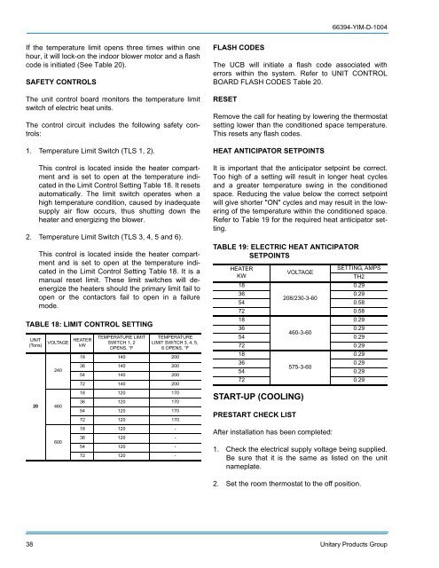
If the temperature limit opens three times within one<br />
hour, it will lock-on the indoor blower motor and a flash<br />
code is initiated (See Table 20).<br />
SAFETY CONTROLS<br />
The unit control board monitors the temperature limit<br />
switch of electric heat units.<br />
The control circuit includes the following safety controls:<br />
1. Temperature Limit Switch (TLS 1, 2).<br />
This control is located inside the heater compartment<br />
and is set to open at the temperature indicated<br />
in the Limit Control Setting Table 18. It resets<br />
automatically. The limit switch operates when a<br />
high temperature condition, caused by inadequate<br />
supply air flow occurs, thus shutting down the<br />
heater and energizing the blower.<br />
2. Temperature Limit Switch (TLS 3, 4, 5 and 6).<br />
This control is located inside the heater compartment<br />
and is set to open at the temperature indicated<br />
in the Limit Control Setting Table 18. It is a<br />
manual reset limit. These limit switches will deenergize<br />
the heaters should the primary limit fail to<br />
open or the contactors fail to open in a failure<br />
mode.<br />
TABLE 18: L<strong>IM</strong>IT CONTROL SETTING<br />
UNIT<br />
(Tons)<br />
20<br />
VOLTAGE<br />
240<br />
460<br />
600<br />
HEATER<br />
kW<br />
TEMPERATURE L<strong>IM</strong>IT<br />
SWITCH 1, 2<br />
OPENS, °F<br />
TEMPERATURE<br />
L<strong>IM</strong>IT SWITCH 3, 4, 5,<br />
6 OPENS, °F<br />
18 140 200<br />
36 140 200<br />
54 140 200<br />
72 140 200<br />
18 120 170<br />
36 120 170<br />
54 120 170<br />
72 120 170<br />
18 120 -<br />
36 120 -<br />
54 120 -<br />
72 120 -<br />
FLASH CODES<br />
The UCB will initiate a flash code associated with<br />
errors within the system. Refer to UNIT CONTROL<br />
BOARD FLASH CODES Table 20.<br />
RESET<br />
Remove the call for heating by lowering the thermostat<br />
setting lower than the conditioned space temperature.<br />
This resets any flash codes.<br />
HEAT ANTICIPATOR SETPOINTS<br />
It is important that the anticipator setpoint be correct.<br />
Too high of a setting will result in longer heat cycles<br />
and a greater temperature swing in the conditioned<br />
space. Reducing the value below the correct setpoint<br />
will give shorter "ON" cycles and may result in the lowering<br />
of the temperature within the conditioned space.<br />
Refer to Table 19 for the required heat anticipator setting.<br />
TABLE 19: ELECTRIC HEAT ANTICIPATOR<br />
SETPOINTS<br />
HEATER<br />
SETTING, AMPS<br />
VOLTAGE<br />
KW<br />
TH2<br />
18<br />
0.29<br />
36 0.29<br />
208/230-3-60<br />
54 0.58<br />
72 0.58<br />
18<br />
0.29<br />
36 0.29<br />
460-3-60<br />
54 0.29<br />
72 0.29<br />
18<br />
0.29<br />
36 0.29<br />
575-3-60<br />
54 0.29<br />
72 0.29<br />
START-UP (COOLING)<br />
PRESTART CHECK LIST<br />
After installation has been completed:<br />
1. Check the electrical supply voltage being supplied.<br />
Be sure that it is the same as listed on the unit<br />
nameplate.<br />
2. Set the room thermostat to the off position.<br />
38 Unitary Products Group