Y-IM, BQ240 Sunline 2000 Single Package Heat Pump
Y-IM, BQ240 Sunline 2000 Single Package Heat Pump
Y-IM, BQ240 Sunline 2000 Single Package Heat Pump

Create successful ePaper yourself
Turn your PDF publications into a flip-book with our unique Google optimized e-Paper software.
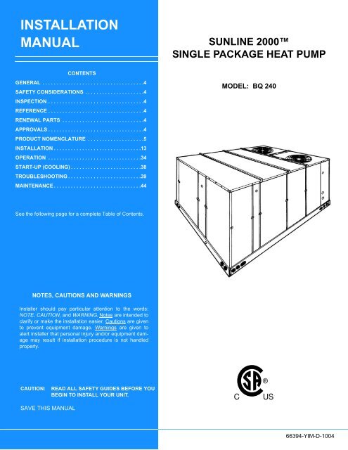
INSTALLATION<br />
MANUAL<br />
CONTENTS<br />
GENERAL . . . . . . . . . . . . . . . . . . . . . . . . . . . . . . . . . . . .4<br />
SAFETY CONSIDERATIONS . . . . . . . . . . . . . . . . . . . . .4<br />
INSPECTION . . . . . . . . . . . . . . . . . . . . . . . . . . . . . . . . . .4<br />
REFERENCE . . . . . . . . . . . . . . . . . . . . . . . . . . . . . . . . . .4<br />
RENEWAL PARTS . . . . . . . . . . . . . . . . . . . . . . . . . . . . .4<br />
APPROVALS . . . . . . . . . . . . . . . . . . . . . . . . . . . . . . . . . .4<br />
PRODUCT NOMENCLATURE . . . . . . . . . . . . . . . . . . . .5<br />
INSTALLATION . . . . . . . . . . . . . . . . . . . . . . . . . . . . . . .13<br />
OPERATION . . . . . . . . . . . . . . . . . . . . . . . . . . . . . . . . .34<br />
START-UP (COOLING) . . . . . . . . . . . . . . . . . . . . . . . . .38<br />
TROUBLESHOOTING . . . . . . . . . . . . . . . . . . . . . . . . . .39<br />
MAINTENANCE . . . . . . . . . . . . . . . . . . . . . . . . . . . . . . .44<br />
SUNLINE <strong>2000</strong><br />
SINGLE PACKAGE HEAT PUMP<br />
MODEL: BQ 240<br />
See the following page for a complete Table of Contents.<br />
NOTES, CAUTIONS AND WARNINGS<br />
Installer should pay particular attention to the words:<br />
NOTE, CAUTION, and WARNING. Notes are intended to<br />
clarify or make the installation easier. Cautions are given<br />
to prevent equipment damage. Warnings are given to<br />
alert installer that personal injury and/or equipment damage<br />
may result if installation procedure is not handled<br />
properly.<br />
CAUTION:<br />
READ ALL SAFETY GUIDES BEFORE YOU<br />
BEGIN TO INSTALL YOUR UNIT.<br />
SAVE THIS MANUAL<br />
66394-Y<strong>IM</strong>-D-1004
66394-Y<strong>IM</strong>-D-1004<br />
TABLE OF CONTENTS<br />
GENERAL. . . . . . . . . . . . . . . . . . . . . . . . . . . . . . . . . . . . . . . 4<br />
SAFETY CONSIDERATIONS . . . . . . . . . . . . . . . . . . . . . . . 4<br />
INSPECTION . . . . . . . . . . . . . . . . . . . . . . . . . . . . . . . . . . . . 4<br />
REFERENCE . . . . . . . . . . . . . . . . . . . . . . . . . . . . . . . . . . . . 4<br />
RENEWAL PARTS. . . . . . . . . . . . . . . . . . . . . . . . . . . . . . . . 4<br />
APPROVALS . . . . . . . . . . . . . . . . . . . . . . . . . . . . . . . . . . . . 4<br />
PRODUCT NOMENCLATURE. . . . . . . . . . . . . . . . . . . . . . . 5<br />
INSTALLATION . . . . . . . . . . . . . . . . . . . . . . . . . . . . . . . . . 13<br />
INSTALLATION SAFETY INFORMATION . . . . . . . . . . . 13<br />
L<strong>IM</strong>ITATIONS . . . . . . . . . . . . . . . . . . . . . . . . . . . . . . . . . 13<br />
LOCATION . . . . . . . . . . . . . . . . . . . . . . . . . . . . . . . . . . . 13<br />
RIGGING AND HANDLING . . . . . . . . . . . . . . . . . . . . . . 14<br />
CLEARANCES . . . . . . . . . . . . . . . . . . . . . . . . . . . . . . . . 14<br />
DUCTWORK. . . . . . . . . . . . . . . . . . . . . . . . . . . . . . . . . . 14<br />
FIXED OUTDOOR AIR INTAKE DAMPER . . . . . . . . . . 15<br />
CONDENSATE DRAIN. . . . . . . . . . . . . . . . . . . . . . . . . . 15<br />
COMPRESSORS . . . . . . . . . . . . . . . . . . . . . . . . . . . . . . 16<br />
FILTERS . . . . . . . . . . . . . . . . . . . . . . . . . . . . . . . . . . . . . 16<br />
SERVICE ACCESS . . . . . . . . . . . . . . . . . . . . . . . . . . . . 16<br />
THERMOSTAT . . . . . . . . . . . . . . . . . . . . . . . . . . . . . . . . 18<br />
POWER AND CONTROL WIRING. . . . . . . . . . . . . . . . . 18<br />
OPTIONAL ELECTRIC HEAT . . . . . . . . . . . . . . . . . . . . 18<br />
OPTIONAL ECONOMIZER/MOTORIZED<br />
DAMPER RAIN HOOD . . . . . . . . . . . . . . . . . . . . . . . . 18<br />
OPTIONAL POWER EXHAUST/BAROMETRIC<br />
RELIEF DAMPER AND RAIN HOOD . . . . . . . . . . . . . 19<br />
OPTIONAL ECONOMIZER AND POWER<br />
EXHAUST DAMPER SET POINT ADJUSTMENTS<br />
AND INFORMATION . . . . . . . . . . . . . . . . . . . . . . . . . . 19<br />
MIN<strong>IM</strong>UM POSITION ADJUSTMENT . . . . . . . . . . . . . 19<br />
ENTHALPY SET POINT ADJUSTMENT. . . . . . . . . . . 19<br />
POWER EXHAUST DAMPER SETPOINT (WITH<br />
OR WITHOUT POWER EXHAUST) . . . . . . . . . . . . . . 19<br />
INDOOR AIR QUALITY AQ. . . . . . . . . . . . . . . . . . . . . 19<br />
CFM, STATIC PRESSURE, AND POWER - ALTITUDE<br />
AND TEMPERATURE CORRECTIONS . . . . . . . . . . . . 28<br />
PHASING . . . . . . . . . . . . . . . . . . . . . . . . . . . . . . . . . . . . 32<br />
CHECKING SUPPLY AIR CFM . . . . . . . . . . . . . . . . . . . 32<br />
AIR BALANCE . . . . . . . . . . . . . . . . . . . . . . . . . . . . . . 33<br />
OPERATION. . . . . . . . . . . . . . . . . . . . . . . . . . . . . . . . . . . . 34<br />
SEQUENCE OF OPERATIONS OVERVIEW. . . . . . . . . 34<br />
COOLING SEQUENCE OF OPERATION . . . . . . . . . . . 34<br />
CONTINUOUS BLOWER . . . . . . . . . . . . . . . . . . . . . . 34<br />
INTERMITTENT BLOWER . . . . . . . . . . . . . . . . . . . . . 34<br />
NO OUTDOOR AIR OPTIONS . . . . . . . . . . . . . . . . . . 34<br />
ECONOMIZER WITH SINGLE ENTHALPY<br />
SENSOR . . . . . . . . . . . . . . . . . . . . . . . . . . . . . . . . . . . 34<br />
ECONOMIZER WITH DUAL ENTHALPY SENSORS. 35<br />
ECONOMIZER WITH POWER EXHAUST . . . . . . . . . 35<br />
MOTORIZED OUTDOOR AIR DAMPERS . . . . . . . . . 35<br />
COOLING OPERATION ERRORS . . . . . . . . . . . . . . . 35<br />
HIGH-PRESSURE L<strong>IM</strong>IT SWITCH . . . . . . . . . . . . . . . 35<br />
LOW-PRESSURE L<strong>IM</strong>IT SWITCH . . . . . . . . . . . . . . . 35<br />
FREEZESTAT . . . . . . . . . . . . . . . . . . . . . . . . . . . . . . . 35<br />
LOW AMBIENT COOLING . . . . . . . . . . . . . . . . . . . . . 36<br />
SAFETY CONTROLS . . . . . . . . . . . . . . . . . . . . . . . . . . 36<br />
COMPRESSOR PROTECTION. . . . . . . . . . . . . . . . . . . 36<br />
FLASH CODES . . . . . . . . . . . . . . . . . . . . . . . . . . . . . . . 36<br />
RESET . . . . . . . . . . . . . . . . . . . . . . . . . . . . . . . . . . . . . . 36<br />
HEATING SEQUENCE OF OPERATIONS . . . . . . . . . . 36<br />
WITH ELECTRIC HEAT . . . . . . . . . . . . . . . . . . . . . . . 36<br />
WITHOUT ELECTRIC HEAT . . . . . . . . . . . . . . . . . . . 37<br />
HEATING OPERATION ERRORS. . . . . . . . . . . . . . . . . 37<br />
TEMPERATURE L<strong>IM</strong>IT . . . . . . . . . . . . . . . . . . . . . . . . 37<br />
SAFETY CONTROLS . . . . . . . . . . . . . . . . . . . . . . . . . . 38<br />
FLASH CODES . . . . . . . . . . . . . . . . . . . . . . . . . . . . . . . 38<br />
RESET . . . . . . . . . . . . . . . . . . . . . . . . . . . . . . . . . . . . . . 38<br />
HEAT ANTICIPATOR SETPOINTS . . . . . . . . . . . . . . . . 38<br />
START-UP (COOLING) . . . . . . . . . . . . . . . . . . . . . . . . . . . 38<br />
PRESTART CHECK LIST . . . . . . . . . . . . . . . . . . . . . . . 38<br />
OPERATING INSTRUCTIONS . . . . . . . . . . . . . . . . . . . 39<br />
POST START CHECK LIST. . . . . . . . . . . . . . . . . . . . . . 39<br />
SHUT DOWN . . . . . . . . . . . . . . . . . . . . . . . . . . . . . . . . . 39<br />
TROUBLESHOOTING . . . . . . . . . . . . . . . . . . . . . . . . . . . . 39<br />
COOLING TROUBLESHOOTING GUIDE . . . . . . . . . . . 39<br />
UNIT FLASH CODES. . . . . . . . . . . . . . . . . . . . . . . . . . . 43<br />
MAINTENANCE . . . . . . . . . . . . . . . . . . . . . . . . . . . . . . . . . 44<br />
NORMAL MAINTENANCE. . . . . . . . . . . . . . . . . . . . . . . 44<br />
FILTERS. . . . . . . . . . . . . . . . . . . . . . . . . . . . . . . . . . . . . 44<br />
MOTORS . . . . . . . . . . . . . . . . . . . . . . . . . . . . . . . . . . . . 44<br />
BLOWER SHAFT BEARING . . . . . . . . . . . . . . . . . . . . . 44<br />
OUTDOOR COIL . . . . . . . . . . . . . . . . . . . . . . . . . . . . . . 44<br />
2 Unitary Products Group
66394-Y<strong>IM</strong>-D-1004<br />
LIST OF FIGURES<br />
Fig. # Pg. #<br />
1 TYPICAL RIGGING. . . . . . . . . . . . . . . . . . . . . . . . . . . 14<br />
2 CENTER OF GRAVITY. . . . . . . . . . . . . . . . . . . . . . . . 14<br />
3 FIXED OUTDOOR AIR DAMPER . . . . . . . . . . . . . . . . 15<br />
4 RECOMMENDED DRAIN PIPING . . . . . . . . . . . . . . . 16<br />
5 TYPICAL FIELD WIRING . . . . . . . . . . . . . . . . . . . . . . 17<br />
6 ENTHALPY SETPOINT ADJUSTMENT . . . . . . . . . . . 20<br />
7 HONEYWELL ECONOMIZER CONTROL W7212 . . . 21<br />
8 FOUR AND SIX POINT LOADS . . . . . . . . . . . . . . . . . 21<br />
9 CENTER OF GRAVITY. . . . . . . . . . . . . . . . . . . . . . . . 22<br />
10 UNIT D<strong>IM</strong>ENSIONS - 20 TON. . . . . . . . . . . . . . . . . . . 26<br />
11 DETAIL “X” ACCY. SIDE SUPPLY & RETURN<br />
AIR OPENINGS . . . . . . . . . . . . . . . . . . . . . . . . . . . . . 27<br />
12 DETAIL “Y” UNIT WITH RAIN HOODS. . . . . . . . . . . . 27<br />
13 ALTITUDE/TEMPERATURE CONVERSION<br />
FACTOR . . . . . . . . . . . . . . . . . . . . . . . . . . . . . . . . . . . 29<br />
14 BELT ADJUSTMENT . . . . . . . . . . . . . . . . . . . . . . . . . 32<br />
15 PRESSURE DROP ACROSS A DRY<br />
INDOOR COIL VS SUPPLY AIR CFM . . . . . . . . . . . . 33<br />
LIST OF TABLES<br />
Tbl. # Pg. #<br />
1 UNIT APPLICATION DATA. . . . . . . . . . . . . . . . . . . . . 13<br />
2 CONTROL WIRE SIZES . . . . . . . . . . . . . . . . . . . . . . . 18<br />
3 ELECTRIC HEAT APPLICATION DATA. . . . . . . . . . . 18<br />
4 FOUR AND SIX POINT LOADS . . . . . . . . . . . . . . . . . 22<br />
5 PHYSICAL DATA - BASIC UNIT. . . . . . . . . . . . . . . . . 23<br />
6 OPERATING WEIGHTS (LBS.) . . . . . . . . . . . . . . . . . 23<br />
7 VOLTAGE L<strong>IM</strong>ITATIONS . . . . . . . . . . . . . . . . . . . . . . 24<br />
8 ELECTRICAL DATA -WITHOUT POWERED<br />
CONVENIENCE OUTLET . . . . . . . . . . . . . . . . . . . . . . 24<br />
9 ELECTRICAL DATA -WITH POWERED<br />
CONVENIENCE OUTLET . . . . . . . . . . . . . . . . . . . . . . 25<br />
10 ELECTRIC HEAT CORRECTION FACTORS. . . . . . . 25<br />
11 MIN<strong>IM</strong>UM CLEARANCES . . . . . . . . . . . . . . . . . . . . . . 26<br />
12 UTILITIES ENTRY DATA . . . . . . . . . . . . . . . . . . . . . . 26<br />
13 ALTITUDE CORRECTION FACTORS . . . . . . . . . . . . 28<br />
14 BLOWER PERFORMANCE 20 TON SUPPLY<br />
AIR BOTTOM DUCT CONNECTIONS . . . . . . . . . . . . 30<br />
15 STATIC RESISTANCES . . . . . . . . . . . . . . . . . . . . . . . 31<br />
16 POWER EXHAUST PERFORMANCE . . . . . . . . . . . . 31<br />
17 BLOWER MOTOR AND DRIVE DATA . . . . . . . . . . . . 31<br />
18 L<strong>IM</strong>IT CONTROL SETTING . . . . . . . . . . . . . . . . . . . . 38<br />
19 ELECTRIC HEAT ANTICIPATOR SETPOINTS . . . . . 38<br />
20 UNIT CONTROL BOARD FLASH CODES . . . . . . . . . 44<br />
Unitary Products Group 3
66394-Y<strong>IM</strong>-D-1004<br />
GENERAL<br />
YORK ® Model BQ units are single package heat<br />
pumps equipped with optional factory installed electric<br />
heaters. These are designed for outdoor installation on<br />
a rooftop or slab.<br />
The units are completely assembled on rigid, permanently<br />
attached base rails. All piping, refrigerant<br />
charge, and electrical wiring is factory installed and<br />
tested. The units require electric power, gas connection,<br />
duct connections, installation of combustion air<br />
inlet hood, flue gas outlet hoods and fixed outdoor air<br />
intake damper (units without economizer or motorized<br />
damper option only) at the point of installation.<br />
The supplemental electric heaters have nickel-chrome<br />
elements and utilize single point power connection.<br />
SAFETY CONSIDERATIONS<br />
Due to system pressure, moving parts and electrical<br />
components, installation and servicing of air conditioning<br />
equipment can be hazardous. Only qualified,<br />
trained, service personnel should install, repair, maintain<br />
or service this equipment.<br />
Observe all precautions in the literature, on labels and<br />
tags accompanying the equipment whenever working<br />
on air conditioning equipment. Be sure to follow all<br />
other safety precautions that apply.<br />
• 035-19856-000 - Barometric Relief Damper<br />
Accessory<br />
• 035-19854-000 - Economizer Damper<br />
Accessory<br />
RENEWAL PARTS<br />
Refer to Renewal Parts Manual for complete listing of<br />
replacement parts on this equipment. Part Number<br />
035-19284-000.<br />
APPROVALS<br />
Design certified by CSA as follows:<br />
• For use as a heat pump only with or without<br />
optional electric heat.<br />
• For outdoor installation only.<br />
• For installation on combustible material.<br />
This product must be installed in strict compliance<br />
with the enclosed installation instructions<br />
and any applicable local, state, and national<br />
codes including, but not limited to, building,<br />
electrical, and mechanical codes.<br />
Wear safety glasses and work gloves, and follow all<br />
safety codes. Use a quenching cloth and have a fire<br />
extinguisher available for all brazing operations.<br />
INSPECTION<br />
As soon as a unit is received, it should be inspected for<br />
possible damage during transit. If damage is evident,<br />
the extent of the damage should be noted on the carrier's<br />
freight bill. A separate request for inspection by<br />
the carrier's agent should be made in writing. Refer to<br />
Form 50.15-NM for additional information.<br />
REFERENCE<br />
Additional information on the design, installation, operation<br />
and service of this equipment is available in the<br />
following reference forms:<br />
Improper installation may create a condition<br />
where the operation of the product could cause<br />
personal injury or property damage.<br />
Installer should pay particular attention to the words:<br />
NOTE, CAUTION and WARNING. Notes are intended<br />
to clarify or make the installation easier. Cautions are<br />
given to prevent equipment damage. Warnings are<br />
given to alert installer that personal injury and/or equipment<br />
damage may result if installation procedure is not<br />
handled properly.<br />
4 Unitary Products Group
66394-Y<strong>IM</strong>-D-1004<br />
PRODUCT NOMENCLATURE<br />
20T <strong>Sunline</strong> <strong>2000</strong> <strong>Heat</strong> <strong>Pump</strong> Model Number Nomenclature<br />
York Brand<br />
B Q 240 C 00 A 2 A AA 1 A<br />
Product Category Product Style<br />
B = <strong>Heat</strong> <strong>Pump</strong>, <strong>Single</strong> <strong>Package</strong> A = Style A<br />
Product Generation<br />
1 = First Generation<br />
Product Identifier<br />
Q= Standard Efficiency <strong>Heat</strong> <strong>Pump</strong><br />
Installation Options Additional Options<br />
A = No Options Installed (See Next Page)<br />
Voltage B = Option 1<br />
1 = 208/230-1-60 C = Option 2<br />
2 = 208/230-3-60 D = Options 1 & 2<br />
Nominal Cooling Capacity - MBH 4 = 460-3-60 E = Option 3<br />
240 = 20 Ton<br />
5 = 575-3-60 F = Options 4<br />
G = Options 1 & 3<br />
H = Options 1 & 4<br />
J = Options 1, 2 & 3<br />
Airflow<br />
K = Options 1, 2, & 4<br />
A= Std Motor/Drive L = Options 1,3 & 4<br />
B = Std Mtr/Drive/<strong>Single</strong> Input Econo M = Options 1, 2, 3, & 4<br />
C = Std Mtr/Drive/<strong>Single</strong> Input Econo/Power Exhaust N = Options 2 & 3<br />
D = Std Mtr/Drive/Motorized Damper P = Options 2 & 4<br />
<strong>Heat</strong> Type & Nominal <strong>Heat</strong> Capacity F = Std Mtr/Drive/4" Filters Q = Options 2, 3, & 4<br />
C00 = Cooling Only. No field installed electric heat G = Std Mtr/Drive/4" Filters/<strong>Single</strong> Input Econ R = Options 3 & 4<br />
Electric <strong>Heat</strong> Options<br />
H = Std Mtr/Drive/4" Filters/<strong>Single</strong> Input Econ/Power Exhaust S = Option 5<br />
E18 = 18 KW<br />
E36 = 36 KW<br />
E54 = 54 KW<br />
E72 = 72 KW<br />
L = Std Mtr/Drive/BAS Ready Econ (No BAS Controller) w/2" Pleated Filters T = Options 1 & 5<br />
M = Std Mtr/Drive/BAS Ready Econ (No BAS Controller)/Power Exhaust w/2" Pleated Filters U = Options 1, 3, & 5<br />
N = Hi Static Drive V = Options 1, 4, & 5<br />
P = Hi Static Drive/<strong>Single</strong> Input Econo W = Options 1, 3, 4, & 5<br />
Q = Hi Static Drive/<strong>Single</strong> Input Econo/Power Exhaust X = Options 3 & 5<br />
R = Hi Static Drive/Motorized Damper Y = Options 4 & 5<br />
T = Hi Static Drive/4" Filters Z = Options 3, 4, & 5<br />
U = Hi Static Drive/4" Filters/<strong>Single</strong> Input Econ Options<br />
V = Hi Static Drive/4" Filters/<strong>Single</strong> Input Econ/Power Exhaust 1 = Disconnect<br />
Y = Hi Static Drive/BAS Ready Econ (No BAS Controller) w/2" Pleated Filters 2 = Non-Pwr'd Conv Oultet<br />
Z = Hi Static Drive/BAS Ready Econ (No BAS Controller)/Power Exhaust w/2" Pleated Filters 3 = Smoke Detector S.A.<br />
4 = Smoke Detector R.A.<br />
5 = Pwr'd Conv. Outlet<br />
Unitary Products Group 5
66394-Y<strong>IM</strong>-D-1004<br />
PRODUCT NOMENCLATURE - CONTINUED<br />
20T <strong>Sunline</strong> <strong>2000</strong> <strong>Heat</strong> <strong>Pump</strong> Model Number Nomenclature<br />
Standard Cabinet<br />
AA<br />
AB<br />
AC<br />
AD<br />
AE<br />
AF<br />
AG<br />
AH<br />
AJ<br />
AK<br />
AL<br />
AM<br />
AN<br />
CA<br />
CB<br />
CC<br />
CD<br />
CE<br />
CF<br />
CG<br />
CH<br />
CJ<br />
CK<br />
CL<br />
CM<br />
CN<br />
CP<br />
CQ<br />
CR<br />
CS<br />
CT<br />
CU<br />
CV<br />
CW<br />
CX<br />
JA<br />
JB<br />
JC<br />
JD<br />
JE<br />
JF<br />
JG<br />
JH<br />
JJ<br />
JK<br />
JL<br />
JM<br />
JN<br />
JP<br />
JQ<br />
JR<br />
None<br />
Phase Monitor<br />
Coil Guard<br />
Dirty Filter Switch<br />
Phase Monitor & Coil Guard<br />
Phase Monitor & Dirty Filter Switch<br />
Coil Guard & Dirty Filter Switch<br />
Phase Monitor, Coil Guard, & Dirty Filter Switch<br />
SS Drain Pan<br />
SS Drain Pan & Phase Monitor<br />
SS Drain Pan & Coil Guard<br />
SS Drain Pan & Dirty Filter Switch<br />
SS Drain Pan, Phase Monitor, Coil Guard & Dirty Filter Switch<br />
CPC Controller with Dirty Filter Switch & Air Proving Switch<br />
CPC Controller, DFS, APS & Phase Monitor<br />
CPC Controller, DFS, APS & Coil Guard<br />
CPC Controller, DFS, APS, Phase Monitor, & Coil Guard<br />
CPC Controller, DFS, APS & Technicoat Cond. Coil<br />
CPC Controller, DFS, APS, Technicoat Cond. Coil, & Phase Monitor<br />
CPC Controller, DFS, APS, Technicoat Cond. Coil, & Coil Guard<br />
CPC Controller, DFS, APS, Technicoat Cond. Coil, Phase Monitor, & Coil Guard<br />
CPC Controller, DFS, APS & Technicoat Evap. Coil<br />
CPC Controller, DFS, APS, Technicoat Evap. Coil, & Phase Monitor<br />
CPC Controller, DFS, APS, Technicoat Evap. Coil, & Coil Guard<br />
CPC Controller, DFS, APS, Technicoat Evap. Coil, Phase Monitor, & Coil Guard<br />
CPC Controller, DFS, APS & Technicoat Evap. & Cond Coils<br />
CPC Controller, DFS, APS, Technicoat Evap. & Cond Coils, & Phase Monitor<br />
CPC Controller, DFS, APS, Technicoat Evap. & Cond Coils, & Coil Guard<br />
CPC Controller, DFS, APS, Technicoat Evap. & Cond Coils, Phase Monitor, & Coil Guard<br />
CPC Controller, DFS, APS, SS Drain Pan<br />
CPC Controller, DFS, APS, SS Drain Pan, Phase Monitor, & Coil Guard<br />
CPC Controller, DFS, APS, SS Drain Pan, & Technicoat Cond Coils<br />
CPC Controller, DFS, APS, SS Drain Pan, & Technicoat Evap Coil<br />
CPC Controller, DFS, APS, SS Drain Pan, & Technicoat Evap and Cond Coils<br />
CPC Controller, DFS, APS, SS Drain Pan, Phase Monitor, Coil Guard, & Technicoat Evap and Cond Coils<br />
Johnson UNT Controller with Dirty Filter Switch & Air Proving Switch<br />
Johnson UNT Controller, DFS, APS & Phase Monitor<br />
Johnson UNT Controller, DFS, APS & Coil Guard<br />
Johnson UNT Controller, DFS, APS, Phase Monitor, & Coil Guard<br />
Johnson UNT Controller, DFS, APS & Technicoat Cond. Coil<br />
Johnson UNT Controller, DFS, APS, Technicoat Cond. Coil, & Phase Monitor<br />
Johnson UNT Controller, DFS, APS, Technicoat Cond. Coil, & Coil Guard<br />
Johnson UNT Controller, DFS, APS, Technicoat Cond. Coil, Phase Monitor, & Coil Guard<br />
Johnson UNT Controller, DFS, APS & Technicoat Evap. Coil<br />
Johnson UNT Controller, DFS, APS, Technicoat Evap. Coil, & Phase Monitor<br />
Johnson UNT Controller, DFS, APS, Technicoat Evap. Coil, & Coil Guard<br />
Johnson UNT Controller, DFS, APS, Technicoat Evap. Coil, Phase Monitor, & Coil Guard<br />
Johnson UNT Controller, DFS, APS & Technicoat Evap. & Cond Coils<br />
Johnson UNT Controller, DFS, APS, Technicoat Evap. & Cond Coils, & Phase Monitor<br />
Johnson UNT Controller, DFS, APS, Technicoat Evap. & Cond Coils, & Coil Guard<br />
Johnson UNT Controller, DFS, APS, Technicoat Evap. & Cond Coils, Phase Monitor, & Coil Guard<br />
6 Unitary Products Group
66394-Y<strong>IM</strong>-D-1004<br />
Standard Cabinet<br />
JS<br />
JT<br />
JU<br />
JV<br />
JW<br />
JX<br />
HA<br />
HB<br />
HC<br />
HD<br />
HE<br />
HF<br />
HG<br />
HH<br />
HJ<br />
HK<br />
HL<br />
HM<br />
HN<br />
HP<br />
HQ<br />
HR<br />
HS<br />
HT<br />
HU<br />
HV<br />
HW<br />
HX<br />
NA<br />
NB<br />
NC<br />
ND<br />
NE<br />
NF<br />
NG<br />
NH<br />
NJ<br />
NK<br />
NL<br />
NM<br />
NN<br />
NP<br />
NQ<br />
NR<br />
NS<br />
NT<br />
NU<br />
NV<br />
NW<br />
NX<br />
TA<br />
TB<br />
TC<br />
TD<br />
TE<br />
Johnson UNT Controller, DFS, APS, SS Drain Pan<br />
Johnson UNT Controller, DFS, APS, SS Drain Pan, Phase Monitor, & Coil Guard<br />
Johnson UNT Controller, DFS, APS, SS Drain Pan, & Technicoat Cond Coils<br />
Johnson UNT Controller, DFS, APS, SS Drain Pan, & Technicoat Evap Coil<br />
Johnson UNT Controller, DFS, APS, SS Drain Pan, & Technicoat Evap and Cond Coils<br />
Johnson UNT Controller, DFS, APS, SS Drain Pan, Phase Monitor, Coil Guard, & Technicoat Evap and Cond Coils<br />
Honeywell Excel 10 Controller with Dirty Filter Switch & Air Proving Switch<br />
Honeywell Excel 10 Controller, DFS, APS & Phase Monitor<br />
Honeywell Excel 10 Controller, DFS, APS & Coil Guard<br />
Honeywell Excel 10 Controller, DFS, APS, Phase Monitor, & Coil Guard<br />
Honeywell Excel 10 Controller, DFS, APS & Technicoat Cond. Coil<br />
Honeywell Excel 10 Controller, DFS, APS, Technicoat Cond. Coil, & Phase Monitor<br />
Honeywell Excel 10 Controller, DFS, APS, Technicoat Cond. Coil, & Coil Guard<br />
Honeywell Excel 10 Controller, DFS, APS, Technicoat Cond. Coil, Phase Monitor, & Coil Guard<br />
Honeywell Excel 10 Controller, DFS, APS & Technicoat Evap. Coil<br />
Honeywell Excel 10 Controller, DFS, APS, Technicoat Evap. Coil, & Phase Monitor<br />
Honeywell Excel 10 Controller, DFS, APS, Technicoat Evap. Coil, & Coil Guard<br />
Honeywell Excel 10 Controller, DFS, APS, Technicoat Evap. Coil, Phase Monitor, & Coil Guard<br />
Honeywell Excel 10 Controller, DFS, APS & Technicoat Evap. & Cond Coils<br />
Honeywell Excel 10 Controller, DFS, APS, Technicoat Evap. & Cond Coils, & Phase Monitor<br />
Honeywell Excel 10 Controller, DFS, APS, Technicoat Evap. & Cond Coils, & Coil Guard<br />
Honeywell Excel 10 Controller, DFS, APS, Technicoat Evap. & Cond Coils, Phase Monitor, & Coil Guard<br />
Honeywell Excel 10 Controller, DFS, APS, SS Drain Pan<br />
Honeywell Excel 10 Controller, DFS, APS, SS Drain Pan, Phase Monitor, & Coil Guard<br />
Honeywell Excel 10 Controller, DFS, APS, SS Drain Pan, & Technicoat Cond Coils<br />
Honeywell Excel 10 Controller, DFS, APS, SS Drain Pan, & Technicoat Evap Coil<br />
Honeywell Excel 10 Controller, DFS, APS, SS Drain Pan, & Technicoat Evap and Cond Coils<br />
Honeywell Excel 10 Controller, DFS, APS, SS Drain Pan, Phase Monitor, Coil Guard, & Technicoat Evap and Cond Coils<br />
Novar ETC-3 Controller with Dirty Filter Switch & Air Proving Switch<br />
Novar ETC-3 Controller, DFS, APS & Phase Monitor<br />
Novar ETC-3 Controller, DFS, APS & Coil Guard<br />
Novar ETC-3 Controller, DFS, APS, Phase Monitor, & Coil Guard<br />
Novar ETC-3 Controller, DFS, APS & Technicoat Cond. Coil<br />
Novar ETC-3 Controller, DFS, APS, Technicoat Cond. Coil, & Phase Monitor<br />
Novar ETC-3 Controller, DFS, APS, Technicoat Cond. Coil, & Coil Guard<br />
Novar ETC-3 Controller, DFS, APS, Technicoat Cond. Coil, Phase Monitor, & Coil Guard<br />
Novar ETC-3 Controller, DFS, APS & Technicoat Evap. Coil<br />
Novar ETC-3 Controller, DFS, APS, Technicoat Evap. Coil, & Phase Monitor<br />
Novar ETC-3 Controller, DFS, APS, Technicoat Evap. Coil, & Coil Guard<br />
Novar ETC-3 Controller, DFS, APS, Technicoat Evap. Coil, Phase Monitor, & Coil Guard<br />
Novar ETC-3 Controller, DFS, APS & Technicoat Evap. & Cond Coils<br />
Novar ETC-3 Controller, DFS, APS, Technicoat Evap. & Cond Coils, & Phase Monitor<br />
Novar ETC-3 Controller, DFS, APS, Technicoat Evap. & Cond Coils, & Coil Guard<br />
Novar ETC-3 Controller, DFS, APS, Technicoat Evap. & Cond Coils, Phase Monitor, & Coil Guard<br />
Novar ETC-3 Controller, DFS, APS, SS Drain Pan<br />
Novar ETC-3 Controller, DFS, APS, SS Drain Pan, Phase Monitor, & Coil Guard<br />
Novar ETC-3 Controller, DFS, APS, SS Drain Pan, & Technicoat Cond Coils<br />
Novar ETC-3 Controller, DFS, APS, SS Drain Pan, & Technicoat Evap Coil<br />
Novar ETC-3, DFS, APS, SS Drain Pan, & Technicoat Evap and Cond Coils<br />
Novar ETC-3 Controller, DFS, APS, SS Drain Pan, Phase Monitor, Coil Guard, & Technicoat Evap and Cond Coils<br />
Technicoat Condenser Coil<br />
Technicoat Condenser Coil & Phase Monitor<br />
Technicoat Condenser Coil & Coil Guard<br />
Technicoat Condenser Coil & Dirty Filter Switch<br />
Technicoat Condenser Coil, Phase Monitor, & Coil Guard<br />
Unitary Products Group 7
66394-Y<strong>IM</strong>-D-1004<br />
Standard Cabinet<br />
TF<br />
TG<br />
TH<br />
TJ<br />
TK<br />
TL<br />
TM<br />
TN<br />
TP<br />
TQ<br />
TR<br />
TS<br />
TT<br />
TU<br />
TV<br />
TW<br />
TX<br />
TY<br />
TZ<br />
T1<br />
T4<br />
T7<br />
LA<br />
LB<br />
LC<br />
LD<br />
LE<br />
LF<br />
LG<br />
LH<br />
LJ<br />
LK<br />
LL<br />
LM<br />
LN<br />
LP<br />
LQ<br />
LR<br />
LS<br />
LT<br />
LU<br />
LV<br />
LW<br />
LX<br />
WA<br />
WB<br />
WC<br />
WD<br />
WE<br />
WF<br />
WG<br />
WH<br />
WJ<br />
WK<br />
Technicoat Condenser Coil, Phase Monitor, & Dirty Filter Switch<br />
Technicoat Condenser Coil, Coil Guard, & Dirty Filter Switch<br />
Technicoat Condenser Coil, Phase Monitor, Coil Guard, & Dirty Filter Switch<br />
Technicoat Evaporator Coil<br />
Technicoat Evaporator Coil & Phase Monitor<br />
Technicoat Evaporator Coil & Coil Guard<br />
Technicoat Evaporator Coil & Dirty Filter Switch<br />
Technicoat Evaporator Coil, Phase Monitor, & Coil Guard<br />
Technicoat Evaporator Coil, Phase Monitor, & Dirty Filter Switch<br />
Technicoat Evaporator Coil, Coil Guard, & Dirty Filter Switch<br />
Technicoat Evaporator Coil, Phase Monitor, Coil Guard, & Dirty Filter Switch<br />
Technicoat Evaporator & Condenser Coils<br />
Technicoat Evaporator & Condenser Coils & Phase Monitor<br />
Technicoat Evaporator & Condenser Coils & Coil Guard<br />
Technicoat Evaporator & Condenser Coils & Dirty Filter Switch<br />
Technicoat Evaporator & Condenser Coils, Phase Monitor, & Coil Guard<br />
Technicoat Evaporator & Condenser Coils, Phase Monitor, & Dirty Filter Switch<br />
Technicoat Evaporator & Condenser Coils, Coil Guard, & Dirty Filter Switch<br />
Technicoat Evaporator & Condenser Coils, Phase Monitor, Coil Guard, & Dirty Filter Switch<br />
Technicoat Condenser & SS Drain Pan<br />
Technicoat Evaporator & SS Drain Pan<br />
Technicoat Evaporator & Condenser Coils & SS Drain Pan<br />
Simplicity Intelli-Comfort Controller<br />
Simplicity Intelli-Comfort Controller, & Phase Monitor<br />
Simplicity Intelli-Comfort Controller, & Coil Guard<br />
Simplicity Intelli-Comfort Controller, Phase Monitor, & Coil Guard<br />
Simplicity Intelli-Comfort Controller, & Technicoat Cond. Coil<br />
Simplicity Intelli-Comfort Controller, Technicoat Cond. Coil, & Phase Monitor<br />
Simplicity Intelli-Comfort Controller, Technicoat Cond. Coil, & Coil Guard<br />
Simplicity Intelli-Comfort Controller, Technicoat Cond. Coil, Phase Monitor, & Coil Guard<br />
Simplicity Intelli-Comfort Controller, & Technicoat Evap. Coil<br />
Simplicity Intelli-Comfort Controller, Technicoat Evap. Coil, & Phase Monitor<br />
Simplicity Intelli-Comfort Controller, Technicoat Evap. Coil, & Coil Guard<br />
Simplicity Intelli-Comfort Controller, Technicoat Evap. Coil, Phase Monitor, & Coil Guard<br />
Simplicity Intelli-Comfort Controller, & Technicoat Evap. & Cond Coils<br />
Simplicity Intelli-Comfort Controller, Technicoat Evap. & Cond Coils, & Phase Monitor<br />
Simplicity Intelli-Comfort Controller, Technicoat Evap. & Cond Coils, & Coil Guard<br />
Simplicity Intelli-Comfort Controller, Technicoat Evap. & Cond Coils, Phase Monitor, & Coil Guard<br />
Simplicity Intelli-Comfort Controller, SS Drain Pan<br />
Simplicity Intelli-Comfort Controller, SS Drain Pan, Phase Monitor, & Coil Guard<br />
Simplicity Intelli-Comfort Controller, SS Drain Pan, & Technicoat Cond Coils<br />
Simplicity Intelli-Comfort Controller, SS Drain Pan, & Technicoat Evap Coil<br />
Simplicity Intelli-Comfort Controller, SS Drain Pan, & Technicoat Evap and Cond Coils<br />
Simplicity Intelli-Comfort Controller, SS Drain Pan, Phase Monitor, Coil Guard, & Technicoat Evap and Cond Coils<br />
Intelli-Comfort w/ModLINC Controller<br />
Intelli-Comfort w/ModLINC Controller, & Phase Monitor<br />
Intelli-Comfort w/ModLINC Controller, & Coil Guard<br />
Intelli-Comfort w/ModLINC Controller, Phase Monitor, & Coil Guard<br />
Intelli-Comfort w/ModLINC Controller, & Technicoat Cond. Coil<br />
Intelli-Comfort w/ModLINC Controller, Technicoat Cond. Coil, & Phase Monitor<br />
Intelli-Comfort w/ModLINC Controller, Technicoat Cond. Coil, & Coil Guard<br />
Intelli-Comfort w/ModLINC Controller, Technicoat Cond. Coil, Phase Monitor, & Coil Guard<br />
Intelli-Comfort w/ModLINC Controller, & Technicoat Evap. Coil<br />
Intelli-Comfort w/ModLINC Controller, Technicoat Evap. Coil, & Phase Monitor<br />
8 Unitary Products Group
66394-Y<strong>IM</strong>-D-1004<br />
Standard Cabinet<br />
WL Intelli-Comfort w/ModLINC Controller, Technicoat Evap. Coil, & Coil Guard<br />
WM Intelli-Comfort w/ModLINC Controller, Technicoat Evap. Coil, Phase Monitor, & Coil Guard<br />
WN Intelli-Comfort w/ModLINC Controller, & Technicoat Evap. & Cond Coils<br />
WP Intelli-Comfort w/ModLINC Controller, Technicoat Evap. & Cond Coils, & Phase Monitor<br />
WQ Intelli-Comfort w/ModLINC Controller, Technicoat Evap. & Cond Coils, & Coil Guard<br />
WR Intelli-Comfort w/ModLINC Controller, Technicoat Evap. & Cond Coils, Phase Monitor, & Coil Guard<br />
WS Intelli-Comfort w/ModLINC Controller, SS Drain Pan<br />
WT Intelli-Comfort w/ModLINC Controller, SS Drain Pan, Phase Monitor, & Coil Guard<br />
WU Intelli-Comfort w/ModLINC Controller, SS Drain Pan, & Technicoat Cond Coils<br />
WV Intelli-Comfort w/ModLINC Controller, SS Drain Pan, & Technicoat Evap Coil<br />
WW Intelli-Comfort w/ModLINC Controller, SS Drain Pan, & Technicoat Evap and Cond Coils<br />
WX Intelli-Comfort w/ModLINC Controller, SS Drain Pan, Phase Monitor, Coil Guard, & Technicoat Evap and Cond Coils<br />
Hinged Filter Door & Toolless Access Cabinet<br />
BA<br />
BB<br />
BC<br />
BD<br />
BE<br />
BF<br />
BG<br />
BH<br />
BJ<br />
BK<br />
BL<br />
BM<br />
BN<br />
DA<br />
DB<br />
DC<br />
DD<br />
DE<br />
DF<br />
DG<br />
DH<br />
DJ<br />
DK<br />
DL<br />
DM<br />
DN<br />
DP<br />
DQ<br />
DR<br />
DS<br />
DT<br />
DU<br />
DV<br />
DW<br />
DX<br />
EA<br />
EB<br />
EC<br />
ED<br />
Hinged Filter Door & Toolless Access Panels<br />
Phase Monitor, Hinged Filter Door & Toolless Access Panels<br />
Coil Guard, Hinged Filter Door & Toolless Access Panels<br />
Dirty Filter Switch, Hinged Filter Door & Toolless Access Panels<br />
Phase Monitor & Coil Guard, Hinged Filter Door & Toolless Access Panels<br />
Phase Monitor & Dirty Filter Switch, Hinged Filter Door & Toolless Access Panels<br />
Coil Guard & Dirty Filter Switch, Hinged Filter Door & Toolless Access Panels<br />
Phase Monitor, Coil Guard, & Dirty Filter Switch, Hinged Filter Door & Toolless Access Panels<br />
SS Drain Pan & Hinged Filter Door & Toolless Access Panels<br />
SS Drain Pan & Phase Monitor, Hinged Filter Door & Toolless Access Panels<br />
SS Drain Pan & Coil Guard, Hinged Filter Door & Toolless Access Panels<br />
SS Drain Pan & Dirty Filter Switch, Hinged Filter Door & Toolless Access Panels<br />
SS Drain Pan & Phase Monitor & Coil Guard, Dirty Filter Switch, Hinged Filter Door & Toolless Access Panels<br />
CPC Controller with Dirty Filter Switch & Air Proving Switch, Hinged Filter Door & Toolless Access Panels<br />
CPC Controller, DFS, APS & Phase Monitor, Hinged Filter Door & Toolless Access Panels<br />
CPC Controller, DFS, APS & Coil Guard, Hinged Filter Door & Toolless Access Panels<br />
CPC Controller, DFS, APS, Phase Monitor, & Coil Guard, Hinged Filter Door & Toolless Access Panels<br />
CPC Controller, DFS, APS & Technicoat Cond. Coil, Hinged Filter Door & Toolless Access Panels<br />
CPC Controller, DFS, APS, Technicoat Cond. Coil, & Phase Monitor, Hinged Filter Door & Toolless Access Panels<br />
CPC Controller, DFS, APS, Technicoat Cond. Coil, & Coil Guard, Hinged Filter Door & Toolless Access Panels<br />
CPC Controller, DFS, APS, Technicoat Cond. Coil, Phase Monitor, & Coil Guard, Hinged Filter Door & Toolless Access Panels<br />
CPC Controller, DFS, APS & Technicoat Evap. Coil, Hinged Filter Door & Toolless Access Panels<br />
CPC Controller, DFS, APS, Technicoat Evap. Coil, & Phase Monitor, Hinged Filter Door & Toolless Access Panels<br />
CPC Controller, DFS, APS, Technicoat Evap. Coil, & Coil Guard, Hinged Filter Door & Toolless Access Panels<br />
CPC Controller, DFS, APS, Technicoat Evap. Coil, Phase Monitor, & Coil Guard, Hinged Filter Door & Toolless Access Panels<br />
CPC Controller, DFS, APS & Technicoat Evap. & Cond Coils, Hinged Filter Door & Toolless Access Panels<br />
CPC Controller, DFS, APS, Technicoat Evap. & Cond Coils, & Phase Monitor, Hinged Filter Door & Toolless Access Panels<br />
CPC Controller, DFS, APS, Technicoat Evap. & Cond Coils, & Coil Guard, Hinged Filter Door & Toolless Access Panels<br />
CPC Controller, DFS, APS, Technicoat Evap. & Cond Coils, Phase Monitor, & Coil Guard, Hinged Filter Door & Toolless Access Panels<br />
CPC Controller, DFS, APS, SS Drain Pan Hinged Filter Door & Toolless Access Panels<br />
CPC Controller, DFS, APS, SS Drain Pan, Phase Monitor, & Coil Guard Hinged Filter Door & Toolless Access Panels<br />
CPC Controller, DFS, APS, SS Drain Pan, & Technicoat Cond Coils Hinged Filter Door & Toolless Access Panels<br />
CPC Controller, DFS, APS, SS Drain Pan, & Technicoat Evap Coil Hinged Filter Door & Toolless Access Panels<br />
CPC Controller, DFS, APS, SS Drain Pan, & Technicoat Evap and Cond Coils Hinged Filter Door & Toolless Access Panels<br />
CPC Controller, DFS, APS, SS Drain Pan, Phase Monitor, Coil Guard, & Technicoat Evap and Cond Coils Hinged Filter Door & Toolless<br />
Access Panels<br />
Johnson UNT Controller with Dirty Filter Switch & Air Proving Switch, Hinged Filter Door & Toolless Access Panels<br />
Johnson UNT Controller, DFS, APS & Phase Monitor, Hinged Filter Door & Toolless Access Panels<br />
Johnson UNT Controller, DFS, APS & Coil Guard, Hinged Filter Door & Toolless Access Panels<br />
Johnson UNT Controller, DFS, APS, Phase Monitor, & Coil Guard, Hinged Filter Door & Toolless Access Panels<br />
Unitary Products Group 9
66394-Y<strong>IM</strong>-D-1004<br />
Hinged Filter Door & Toolless Access Cabinet<br />
EE<br />
EF<br />
EG<br />
EH<br />
EJ<br />
EK<br />
EL<br />
EM<br />
EN<br />
EP<br />
EQ<br />
ER<br />
ES<br />
ET<br />
EU<br />
EV<br />
EW<br />
EX<br />
GA<br />
GB<br />
GC<br />
GD<br />
GE<br />
GF<br />
GG<br />
GH<br />
GJ<br />
GK<br />
GL<br />
GM<br />
GN<br />
GP<br />
GQ<br />
GR<br />
GS<br />
GT<br />
GU<br />
GV<br />
GW<br />
GX<br />
PA<br />
PB<br />
PC<br />
PD<br />
PE<br />
PF<br />
PG<br />
PH<br />
PJ<br />
Johnson UNT Controller, DFS, APS & Technicoat Cond. Coil, Hinged Filter Door & Toolless Access Panels<br />
Johnson UNT Controller, DFS, APS, Technicoat Cond. Coil, & Phase Monitor, Hinged Filter Door & Toolless Access Panels<br />
Johnson UNT Controller, DFS, APS, Technicoat Cond. Coil, & Coil Guard, Hinged Filter Door & Toolless Access Panels<br />
Johnson UNT Controller, DFS, APS, Technicoat Cond. Coil, Phase Monitor, & Coil Guard, Hinged Filter Door & Toolless Access Panels<br />
Johnson UNT Controller, DFS, APS & Technicoat Evap. Coil, Hinged Filter Door & Toolless Access Panels<br />
Johnson UNT Controller, DFS, APS, Technicoat Evap. Coil, & Phase Monitor, Hinged Filter Door & Toolless Access Panels<br />
Johnson UNT Controller, DFS, APS, Technicoat Evap. Coil, & Coil Guard, Hinged Filter Door & Toolless Access Panels<br />
Johnson UNT Controller, DFS, APS, Technicoat Evap. Coil, Phase Monitor, & Coil Guard, Hinged Filter Door & Toolless Access Panels<br />
Johnson UNT Controller, DFS, APS & Technicoat Evap. & Cond Coils, Hinged Filter Door & Toolless Access Panels<br />
Johnson UNT Controller, DFS, APS, Technicoat Evap. & Cond Coils, & Phase Monitor, Hinged Filter Door & Toolless Access Panels<br />
Johnson UNT Controller, DFS, APS, Technicoat Evap. & Cond Coils, & Coil Guard, Hinged Filter Door & Toolless Access Panels<br />
Johnson UNT Controller, DFS, APS, Technicoat Evap. & Cond Coils, Phase Monitor, & Coil Guard, Hinged Filter Door & Toolless Access<br />
Panels<br />
Johnson UNT Controller, DFS, APS, SS Drain Pan Hinged Filter Door & Toolless Access Panels<br />
Johnson UNT Controller, DFS, APS, SS Drain Pan, Phase Monitor, & Coil Guard Hinged Filter Door & Toolless Access Panels<br />
Johnson UNT Controller, DFS, APS, SS Drain Pan, & Technicoat Cond Coils Hinged Filter Door & Toolless Access Panels<br />
Johnson UNT Controller, DFS, APS, SS Drain Pan, & Technicoat Evap Coil Hinged Filter Door & Toolless Access Panels<br />
Johnson UNT Controller, DFS, APS, SS Drain Pan, & Technicoat Evap and Cond Coils Hinged Filter Door & Toolless Access Panels<br />
Johnson UNT Controller, DFS, APS, SS Drain Pan, Phase Monitor, Coil Guard, & Technicoat Evap and Cond Coils Hinged Filter Door &<br />
Toolless Access Panels<br />
Honeywell Excel 10 Controller with Dirty Filter Switch & Air Proving Switch, Hinged Filter Door & Toolless Access Panels<br />
Honeywell Excel 10 Controller, DFS, APS & Phase Monitor, Hinged Filter Door & Toolless Access Panels<br />
Honeywell Excel 10 Controller, DFS, APS & Coil Guard, Hinged Filter Door & Toolless Access Panels<br />
Honeywell Excel 10 Controller, DFS, APS, Phase Monitor, & Coil Guard, Hinged Filter Door & Toolless Access Panels<br />
Honeywell Excel 10 Controller, DFS, APS & Technicoat Cond. Coil, Hinged Filter Door & Toolless Access Panels<br />
Honeywell Excel 10 Controller, DFS, APS, Technicoat Cond. Coil, & Phase Monitor, Hinged Filter Door & Toolless Access Panels<br />
Honeywell Excel 10 Controller, DFS, APS, Technicoat Cond. Coil, & Coil Guard, Hinged Filter Door & Toolless Access Panels<br />
Honeywell Excel 10 Controller, DFS, APS, Technicoat Cond. Coil, Phase Monitor, & Coil Guard, Hinged Filter Door & Toolless Access<br />
Panels<br />
Honeywell Excel 10 Controller, DFS, APS & Technicoat Evap. Coil, Hinged Filter Door & Toolless Access Panels<br />
Honeywell Excel 10 Controller, DFS, APS, Technicoat Evap. Coil, & Phase Monitor, Hinged Filter Door & Toolless Access Panels<br />
Honeywell Excel 10 Controller, DFS, APS, Technicoat Evap. Coil, & Coil Guard, Hinged Filter Door & Toolless Access Panels<br />
Honeywell Excel 10 Controller, DFS, APS, Technicoat Evap. Coil, Phase Monitor, & Coil Guard, Hinged Filter Door & Toolless Access<br />
Panels<br />
Honeywell Excel 10 Controller, DFS, APS & Technicoat Evap. & Cond Coils, Hinged Filter Door & Toolless Access Panels<br />
Honeywell Excel 10 Controller, DFS, APS, Technicoat Evap. & Cond Coils, & Phase Monitor, Hinged Filter Door & Toolless Access<br />
Panels<br />
Honeywell Excel 10 Controller, DFS, APS, Technicoat Evap. & Cond Coils, & Coil Guard, Hinged Filter Door & Toolless Access Panels<br />
Honeywell Excel 10 Controller, DFS, APS, Technicoat Evap. & Cond Coils, Phase Monitor, & Coil Guard, Hinged Filter Door & Toolless<br />
Access Panels<br />
Honeywell Excel 10 Controller, DFS, APS, SS Drain Pan<br />
Honeywell Excel 10 Controller, DFS, APS, SS Drain Pan, Phase Monitor, & Coil Guard<br />
Honeywell Excel 10 Controller, DFS, APS, SS Drain Pan, & Technicoat Cond Coils<br />
Honeywell Excel 10 Controller, DFS, APS, SS Drain Pan, & Technicoat Evap Coil<br />
Honeywell Excel 10 Controller,DFS, APS, SS Drain Pan, & Technicoat Evap and Cond Coils<br />
Honeywell Excel 10 Controller,DFS, APS, SS Drain Pan, Phase Monitor, Coil Guard, & Technicoat Evap and Cond Coils<br />
Novar ETC-3 Controller with Dirty Filter Switch & Air Proving Switch, Hinged Filter Door & Toolless Access Panels<br />
Novar ETC-3 Controller, DFS, APS & Phase Monitor, Hinged Filter Door & Toolless Access Panels<br />
Novar ETC-3 Controller, DFS, APS & Coil Guard, Hinged Filter Door & Toolless Access Panels<br />
Novar ETC-3 Controller, DFS, APS, Phase Monitor, & Coil Guard, Hinged Filter Door & Toolless Access Panels<br />
Novar ETC-3 Controller, DFS, APS & Technicoat Cond. Coil, Hinged Filter Door & Toolless Access Panels<br />
Novar ETC-3 Controller, DFS, APS, Technicoat Cond. Coil, & Phase Monitor, Hinged Filter Door & Toolless Access Panels<br />
Novar ETC-3 Controller, DFS, APS, Technicoat Cond. Coil, & Coil Guard, Hinged Filter Door & Toolless Access Panels<br />
Novar ETC-3 Controller, DFS, APS, Technicoat Cond. Coil, Phase Monitor, & Coil Guard, Hinged Filter Door & Toolless Access Panels<br />
Novar ETC-3 Controller, DFS, APS & Technicoat Evap. Coil, Hinged Filter Door & Toolless Access Panels<br />
10 Unitary Products Group
66394-Y<strong>IM</strong>-D-1004<br />
Hinged Filter Door & Toolless Access Cabinet<br />
PK<br />
PL<br />
PM<br />
PN<br />
PP<br />
PQ<br />
PR<br />
PS<br />
PT<br />
PU<br />
PV<br />
PW<br />
PX<br />
UA<br />
UB<br />
UC<br />
UD<br />
UE<br />
UF<br />
UG<br />
UH<br />
UJ<br />
UK<br />
UL<br />
UM<br />
UN<br />
UP<br />
UQ<br />
UR<br />
US<br />
UT<br />
UU<br />
UV<br />
UW<br />
UX<br />
UY<br />
UZ<br />
U1<br />
U4<br />
U7<br />
QA<br />
QB<br />
QC<br />
QD<br />
QE<br />
QF<br />
QG<br />
QH<br />
QJ<br />
QK<br />
QL<br />
QM<br />
QN<br />
Novar ETC-3 Controller, DFS, APS, Technicoat Evap. Coil, & Phase Monitor, Hinged Filter Door & Toolless Access Panels<br />
Novar ETC-3 Controller, DFS, APS, Technicoat Evap. Coil, & Coil Guard, Hinged Filter Door & Toolless Access Panels<br />
Novar ETC-3 Controller, DFS, APS, Technicoat Evap. Coil, Phase Monitor, & Coil Guard, Hinged Filter Door & Toolless Access Panels<br />
Novar ETC-3 Controller, DFS, APS & Technicoat Evap. & Cond Coils, Hinged Filter Door & Toolless Access Panels<br />
Novar ETC-3 Controller, DFS, APS, Technicoat Evap. & Cond Coils, & Phase Monitor, Hinged Filter Door & Toolless Access Panels<br />
Novar ETC-3 Controller, DFS, APS, Technicoat Evap. & Cond Coils, & Coil Guard, Hinged Filter Door & Toolless Access Panels<br />
Novar ETC-3 Controller, DFS, APS, Technicoat Evap. & Cond Coils, Phase Monitor, & Coil Guard, Hinged Filter Door & Toolless Access<br />
Panels<br />
Novar ETC-3 Controller, DFS, APS, SS Drain Pan<br />
Novar ETC-3 Controller, DFS, APS, SS Drain Pan, Phase Monitor, & Coil Guard<br />
Novar ETC-3 Controller, DFS, APS, SS Drain Pan, & Technicoat Cond Coils<br />
Novar ETC-3 Controller, DFS, APS, SS Drain Pan, & Technicoat Evap Coil<br />
Novar ETC-3, DFS, APS, SS Drain Pan, & Technicoat Evap and Cond Coils<br />
Novar ETC-3 Controller, DFS, APS, SS Drain Pan, Phase Monitor, Coil Guard, & Technicoat Evap and Cond Coils<br />
Technicoat Condenser Coil, Hinged Filter Door & Toolless Access Panels<br />
Technicoat Condenser Coil & Phase Monitor, Hinged Filter Door & Toolless Access Panels<br />
Technicoat Condenser Coil & Coil Guard, Hinged Filter Door & Toolless Access Panels<br />
Technicoat Condenser Coil & Dirty Filter Switch, Hinged Filter Door & Toolless Access Panels<br />
Technicoat Condenser Coil, Phase Monitor, & Coil Guard, Hinged Filter Door & Toolless Access Panels<br />
Technicoat Condenser Coil, Phase Monitor, & Dirty Filter Switch, Hinged Filter Door & Toolless Access Panels<br />
Technicoat Condenser Coil, Coil Guard, & Dirty Filter Switch, Hinged Filter Door & Toolless Access Panels<br />
Technicoat Condenser Coil, Phase Monitor, Coil Guard, & Dirty Filter Switch, Hinged Filter Door & Toolless Access Panels<br />
Technicoat Evaporator Coil, Hinged Filter Door & Toolless Access Panels<br />
Technicoat Evaporator Coil & Phase Monitor, Hinged Filter Door & Toolless Access Panels<br />
Technicoat Evaporator Coil & Coil Guard, Hinged Filter Door & Toolless Access Panels<br />
Technicoat Evaporator Coil & Dirty Filter Switch, Hinged Filter Door & Toolless Access Panels<br />
Technicoat Evaporator Coil, Phase Monitor, & Coil Guard, Hinged Filter Door & Toolless Access Panels<br />
Technicoat Evaporator Coil, Phase Monitor, & Dirty Filter Switch, Hinged Filter Door & Toolless Access Panels<br />
Technicoat Evaporator Coil, Coil Guard, & Dirty Filter Switch, Hinged Filter Door & Toolless Access Panels<br />
Technicoat Evaporator Coil, Phase Monitor, Coil Guard, & Dirty Filter Switch, Hinged Filter Door & Toolless Access Panels<br />
Technicoat Evaporator & Condenser Coils, Hinged Filter Door & Toolless Access Panels<br />
Technicoat Evaporator & Condenser Coils & Phase Monitor, Hinged Filter Door & Toolless Access Panels<br />
Technicoat Evaporator & Condenser Coils & Coil Guard, Hinged Filter Door & Toolless Access Panels<br />
Technicoat Evaporator & Condenser Coils & Dirty Filter Switch, Hinged Filter Door & Toolless Access Panels<br />
Technicoat Evaporator & Condenser Coils, Phase Monitor, & Coil Guard, Hinged Filter Door & Toolless Access Panels<br />
Technicoat Evaporator & Condenser Coils, Phase Monitor, & Dirty Filter Switch, Hinged Filter Door & Toolless Access Panels<br />
Technicoat Evaporator & Condenser Coils, Coil Guard, & Dirty Filter Switch, Hinged Filter Door & Toolless Access Panels<br />
Technicoat Evaporator & Condenser Coils, Phase Monitor, Coil Guard, & Dirty Filter Switch, Hinged Filter Door & Toolless Access Panels<br />
Technicoat Condenser & SS Drain Pan, Hinged Filter Door & Toolless Access Panels<br />
Technicoat Evaporator & SS Drain Pan, Hinged Filter Door and Toolless Access Panels<br />
Technicoat Evaporator & Condenser Coils & SS Drain Pan, Hinged Filter Door & Toolless Access Panels<br />
Simplicity Intelli-Comfort Controller with Hinged Filter Door & Toolless Access Panels<br />
Simplicity Intelli-Comfort Controller, & Phase Monitor, Hinged Filter Door & Toolless Access Panels<br />
Simplicity Intelli-Comfort Controller, & Coil Guard, Hinged Filter Door & Toolless Access Panels<br />
Simplicity Intelli-Comfort Controller, Phase Monitor, & Coil Guard, Hinged Filter Door & Toolless Access Panels<br />
Simplicity Intelli-Comfort Controller, & Technicoat Cond. Coil, Hinged Filter Door & Toolless Access Panels<br />
Simplicity Intelli-Comfort Controller, Technicoat Cond. Coil, & Phase Monitor, Hinged Filter Door & Toolless Access Panels<br />
Simplicity Intelli-Comfort Controller, Technicoat Cond. Coil, & Coil Guard, Hinged Filter Door & Toolless Access Panels<br />
Simplicity Intelli-Comfort Controller, Technicoat Cond. Coil, Phase Monitor, & Coil Guard, Hinged Filter Door & Toolless Access<br />
Simplicity Intelli-Comfort Controller, & Technicoat Evap. Coil, Hinged Filter Door & Toolless Access Panels<br />
Simplicity Intelli-Comfort Controller, Technicoat Evap. Coil, & Phase Monitor, Hinged Filter Door & Toolless Access Panels<br />
Simplicity Intelli-Comfort Controller, Technicoat Evap. Coil, & Coil Guard, Hinged Filter Door & Toolless Access Panels<br />
Simplicity Intelli-Comfort Controller, Technicoat Evap. Coil, Phase Monitor, & Coil Guard, Hinged Filter Door & Toolless Access<br />
Simplicity Intelli-Comfort Controller, & Technicoat Evap. & Cond Coils, Hinged Filter Door & Toolless Access Panels<br />
Unitary Products Group 11
66394-Y<strong>IM</strong>-D-1004<br />
Hinged Filter Door & Toolless Access Cabinet<br />
QP<br />
QQ<br />
QR<br />
QS<br />
QT<br />
QU<br />
QV<br />
QW<br />
QX<br />
XA<br />
XB<br />
XC<br />
XD<br />
XE<br />
XF<br />
XG<br />
XH<br />
XJ<br />
XK<br />
XL<br />
XM<br />
XN<br />
XP<br />
XQ<br />
XR<br />
XS<br />
XT<br />
XU<br />
XV<br />
XW<br />
XX<br />
Simplicity Intelli-Comfort Controller, Technicoat Evap. & Cond Coils, & Phase Monitor, Hinged Filter Door & Toolless Access Pan<br />
Simplicity Intelli-Comfort Controller, Technicoat Evap. & Cond Coils, & Coil Guard, Hinged Filter Door & Toolless Access Panels<br />
Simplicity Intelli-Comfort Controller, Technicoat Evap. & Cond Coils, Phase Monitor, & Coil Guard, Hinged Filter Door & Toolless<br />
Simplicity Intelli-Comfort Controller, SS Drain Pan Hinged Filter Door & Toolless Access Panels<br />
Simplicity Intelli-Comfort Controller, SS Drain Pan, Phase Monitor, & Coil Guard Hinged Filter Door & Toolless Access Panels<br />
Simplicity Intelli-Comfort Controller, SS Drain Pan, & Technicoat Cond Coils Hinged Filter Door & Toolless Access Panels<br />
Simplicity Intelli-Comfort Controller, SS Drain Pan, & Technicoat Evap Coil Hinged Filter Door & Toolless Access Panels<br />
Simplicity Intelli-Comfort Controller, SS Drain Pan, & Technicoat Evap and Cond Coils Hinged Filter Door & Toolless Access Panels<br />
Simplicity Intelli-Comfort Controller, SS Drain Pan, Phase Monitor, Coil Guard, & Technicoat Evap and Cond Coils Hinged Filter Door &<br />
Toolless Access Panels<br />
Intelli-Comfort w/ModLINC Controller, Hinged Filter Door & Toolless Access Panels<br />
Intelli-Comfort w/ModLINC Controller, & Phase Monitor, Hinged Filter Door & Toolless Access Panels<br />
Intelli-Comfort w/ModLINC Controller, & Coil Guard, Hinged Filter Door & Toolless Access Panels<br />
Intelli-Comfort w/ModLINC Controller, Phase Monitor, & Coil Guard, Hinged Filter Door & Toolless Access Panels<br />
Intelli-Comfort w/ModLINC Controller, & Technicoat Cond. Coil, Hinged Filter Door & Toolless Access Panels<br />
Intelli-Comfort w/ModLINC Controller, Technicoat Cond. Coil, & Phase Monitor, Hinged Filter Door & Toolless Access Panels<br />
Intelli-Comfort w/ModLINC Controller, Technicoat Cond. Coil, & Coil Guard, Hinged Filter Door & Toolless Access Panels<br />
Intelli-Comfort w/ModLINC Controller, Technicoat Cond. Coil, Phase Monitor, & Coil Guard, Hinged Filter Door & Toolless Access<br />
Intelli-Comfort w/ModLINC Controller, & Technicoat Evap. Coil, Hinged Filter Door & Toolless Access Panels<br />
Intelli-Comfort w/ModLINC Controller, Technicoat Evap. Coil, & Phase Monitor, Hinged Filter Door & Toolless Access Panels<br />
Intelli-Comfort w/ModLINC Controller, Technicoat Evap. Coil, & Coil Guard, Hinged Filter Door & Toolless Access Panels<br />
Intelli-Comfort w/ModLINC Controller, Technicoat Evap. Coil, Phase Monitor, & Coil Guard, Hinged Filter Door & Toolless Access<br />
Intelli-Comfort w/ModLINC Controller, & Technicoat Evap. & Cond Coils, Hinged Filter Door & Toolless Access Panels<br />
Intelli-Comfort w/ModLINC Controller, Technicoat Evap. & Cond Coils, & Phase Monitor, Hinged Filter Door & Toolless Access Pan<br />
Intelli-Comfort w/ModLINC Controller, Technicoat Evap. & Cond Coils, & Coil Guard, Hinged Filter Door & Toolless Access Panels<br />
Intelli-Comfort w/ModLINC Controller, Technicoat Evap. & Cond Coils, Phase Monitor, & Coil Guard, Hinged Filter Door & Toolless<br />
Intelli-Comfort w/ModLINC Controller, SS Drain Pan Hinged Filter Door & Toolless Access Panels<br />
Intelli-Comfort w/ModLINC Controller, SS Drain Pan, Phase Monitor, & Coil Guard Hinged Filter Door & Toolless Access Panels<br />
Intelli-Comfort w/ModLINC Controller, SS Drain Pan, & Technicoat Cond Coils Hinged Filter Door & Toolless Access Panels<br />
Intelli-Comfort w/ModLINC Controller, SS Drain Pan, & Technicoat Evap Coil Hinged Filter Door & Toolless Access Panels<br />
Intelli-Comfort w/ModLINC Controller, SS Drain Pan, & Technicoat Evap and Cond Coils Hinged Filter Door & Toolless Access Panels<br />
Intelli-Comfort w/ModLINC Controller, SS Drain Pan, Phase Monitor, Coil Guard, & Technicoat Evap and Cond Coils Hinged Filter Door &<br />
Toolless Access Panels<br />
12 Unitary Products Group
66394-Y<strong>IM</strong>-D-1004<br />
INSTALLATION<br />
INSTALLATION SAFETY INFORMATION:<br />
Read these instructions before continuing this appliance<br />
installation. This is an outdoor combination heating<br />
and cooling unit. The installer must assure that<br />
these instructions are made available to the consumer<br />
and with instructions to retain them for future reference.<br />
1. Install this furnace only in a location and position<br />
as specified on Page 13 of these instructions.<br />
2. This equipment is not to be used for temporary<br />
heating of buildings or structures under construction.<br />
L<strong>IM</strong>ITATIONS<br />
These units must be installed in accordance with the<br />
following national and local safety codes:<br />
In U.S.A.:<br />
• National Electrical Code ANSI/NFPA No. 70.<br />
TABLE 1: UNIT APPLICATION DATA<br />
• Local gas utility requirements.<br />
In Canada:<br />
• Current Canadian Electrical Code C22.1.<br />
• Local plumbing and waste water codes.<br />
• Other applicable local codes.<br />
Refer to the Unit Application Data table and to the Electric<br />
<strong>Heat</strong> Application Data table.<br />
If components are to be added to a unit to meet local<br />
codes, they are to be installed at the dealer's and/or<br />
the customer's expense.<br />
Size of unit for proposed installation should be based<br />
on heat loss/heat gain calculation made according to<br />
the methods of the Air Conditioning Contractors of<br />
America (ACCA).<br />
This furnace is not to be used for temporary heating of<br />
buildings or structures under construction.<br />
UNIT MODEL NUMBER<br />
<strong>BQ240</strong><br />
208/230-3-60 187 / 253<br />
Voltage Variation,<br />
Min. / Max. 1 460-3-60 414 / 506<br />
575-3-60 518 / 630<br />
Supply Air CFM, Min. / Max. 6,000 / 9,400<br />
Wet Bulb Temperature (°F) of Air on<br />
Evaporator Coil, Min. / Max.<br />
57 / 72<br />
Dry Bulb Temperature (°F) of Air on<br />
Condenser Coil, Min. / Max.<br />
0 / 120<br />
1. Utilization range “A” in accordance with ARI Standard 110.<br />
LOCATION<br />
Use the following guidelines to select a suitable location<br />
for these units.<br />
1. Unit is designed for outdoor installation only.<br />
2. Condenser coils must have an unlimited supply of<br />
air.<br />
3. Where a choice of location is possible, position the<br />
unit on either north or east side of building.<br />
4. For ground level installation, use a level concrete<br />
slab with a minimum thickness of 4 inches. The<br />
length and width should be at least 6 inches<br />
greater than the unit base rails. Do not tie slab to<br />
the building foundation.<br />
5. Roof structures must be able to support the weight<br />
of the unit and its options and/or accessories. Unit<br />
must be installed on a solid level roof curb or<br />
appropriate angle iron frame.<br />
6. Maintain level tolerance to 1/2 inch maximum<br />
across the entire length or width of the unit.<br />
If a unit is to be installed on a roof curb or special frame<br />
other than a YORK ® roof curb, gasketing must be<br />
applied to all surfaces that come in contact with the unit<br />
underside.<br />
Unitary Products Group 13
66394-Y<strong>IM</strong>-D-1004<br />
RIGGING AND HANDLING<br />
Exercise care when moving the unit. Do not remove<br />
any packaging until the unit is near the place of installation.<br />
Rig the unit by attaching chain or cable slings to<br />
the round lifting holes provided in the base rails.<br />
Spreaders, whose length exceeds the largest dimension<br />
across the unit, MUST BE USED. Refer to<br />
Figure 1.<br />
Units may also be moved or lifted with a forklift, from<br />
the side only, providing that an accessory skid is used.<br />
LENGTH OF FORKS MUST BE A MIN<strong>IM</strong>UM OF 90".<br />
Refer to the Physical Data Table 5 for unit weights and<br />
to the Figures 2 or 12 for approximate center of gravity.<br />
Before lifting a unit, make sure that all panels<br />
are in place and that its weight is distributed<br />
equally on all cables so it will lift evenly.<br />
FIGURE 2 - CENTER OF GRAVITY<br />
CLEARANCES<br />
All units require certain clearances for proper operation<br />
and service. Installer must make provisions for adequate<br />
ventilation air. Refer to Unit Dimensions<br />
Figure 10 and Minimum Clearances Table 11 for the<br />
clearances required for combustible construction, servicing,<br />
and proper unit operation.<br />
1. 6 1 /<br />
0 - 5<br />
FIGURE 1 - TYPICAL RIGGING<br />
5 2 4 - ) , - 4<br />
* ) 4<br />
+ ) 7 6 1 <br />
* - . 4 - 1. 6 1 / 7 16 <br />
) - 5 7 4 - 6 0 ) 6 16 5<br />
9 1, 6 0 15 , 15 6 4 1* 7 6 - ,<br />
- 3 7 ) ; 6 0 - + ) * - 5<br />
5 6 0 ) 6 16 9 1 1. 6<br />
- 8 - ;<br />
Do not permit overhanging structures or shrubs<br />
to obstruct outdoor air discharge outlet, combustion<br />
air inlet or vent outlets.<br />
DUCTWORK<br />
Ductwork should be designed and sized according to<br />
the methods in Manual Q of the Air Conditioning Contractors<br />
of America (ACCA).<br />
A closed return duct system shall be used. This shall<br />
not preclude use of economizers or outdoor fresh air<br />
intake. The supply and return air duct connections at<br />
the unit should be made with flexible joints to minimize<br />
noise.<br />
14 Unitary Products Group
66394-Y<strong>IM</strong>-D-1004<br />
The supply and return air duct systems should be<br />
designed for the CFM and static requirements of the<br />
job. They should NOT be sized to match the dimensions<br />
of the duct connections on the unit.<br />
On units with side return air applications, install the<br />
damper assembly on the return air ductwork as close<br />
to the unit as possible. Cut an opening 16 inches high<br />
by 18 inches wide in the ductwork to accommodate the<br />
damper. Using the holes in the hood flanges as a template,<br />
drill 9/64 inch dia. (#26 drill) holes into the ductwork<br />
and secure with the screws provided.<br />
When fastening ductwork to side duct flanges<br />
on unit, insert screws through duct flanges<br />
only. DO NOT insert screws through casing.<br />
Outdoor ductwork must be insulated and<br />
waterproofed.<br />
Refer to Unit Dimensions Figure 10 for information<br />
concerning side and bottom supply and return air duct<br />
openings.<br />
FIXED OUTDOOR AIR INTAKE DAMPER<br />
This damper is shipped inside the return air compartment.<br />
It is completely assembled and ready for installation.<br />
A damper baffle inside of the hood is adjustable to<br />
provide variable amounts of outdoor air intake on units<br />
that are not provided with an economizer or a motorized<br />
damper option. Refer to the Fixed Outdoor<br />
Damper Figure 3.<br />
Gasketing and mounting screws are provided in a parts<br />
bag attached to the hood assembly. Apply gasketing to<br />
the three flange surfaces on the hood prior to installing<br />
the hood. Extend gasketing 1/4 inch beyond the top<br />
and bottom of the two side flanges to insure adequate<br />
sealing.<br />
Adjusting the damper to the desired air flow may be<br />
done before mounting the hood into position or after<br />
installation by removing the front hood panel or the<br />
screen on the bottom of the hood. Damper baffle in<br />
position 1 will allow approximately 10% outdoor air<br />
flow, position 2 approximately 15% and, to allow<br />
approximately 25%, remove the damper baffle.<br />
On units with bottom return air application install the<br />
damper assembly over the opening in the side return<br />
air access panel. Remove and discard the opening<br />
cover and the covering over the hood mounting holes<br />
(used for shipping) before installing. Secure with the<br />
screws provided.<br />
If outdoor air intake will not be required on<br />
units with bottom return air applications, the<br />
damper assembly should still be mounted on<br />
the side return air access panel, per the<br />
instructions above, to insure moisture is not<br />
drawn into the unit during operation. The covering<br />
over the mounting holes only need be<br />
removed. Do not remove the opening cover.<br />
FIGURE 3 - FIXED OUTDOOR AIR DAMPER<br />
CONDENSATE DRAIN<br />
Plumbing must conform to local codes. Use a sealing<br />
compound on male pipe threads. Install a condensate<br />
drain line from the one-inch NPT female connection on<br />
the unit to an open drain.<br />
NOTE: The condensate drain operates in a negative<br />
pressure in the cabinet. The condensate drain<br />
line MUST be trapped to provide proper drainage.<br />
See Figure 4.<br />
Unitary Products Group 15
66394-Y<strong>IM</strong>-D-1004<br />
evaporator coil and must be kept clean or replaced with<br />
same size and type. Dirty filters will reduce the capacity<br />
of the unit and will result in frosted coils or safety shutdown.<br />
Minimum filter area and required sizes are<br />
shown in Physical Data Table 5.<br />
SERVICE ACCESS<br />
The following removable panels provide access to all<br />
serviceable components:<br />
FIGURE 4 - RECOMMENDED DRAIN PIPING<br />
COMPRESSORS<br />
Units are shipped with compressor mountings factoryadjusted<br />
and ready for operation.<br />
• Compressor compartment<br />
• Electric <strong>Heat</strong> compartment<br />
• Side Supply & Return Air compartments<br />
(Two panels)<br />
• Blower compartment (Three panels)<br />
• Main control box<br />
• Filter compartment<br />
• Outdoor Air compartment (Two panels)<br />
Refer to the Unit Dimensions Figure 10 for location of<br />
these access panels.<br />
Do not loosen compressor mounting bolts.<br />
FILTERS<br />
Two-inch or four-inch filters can be supplied with each<br />
unit. Filters must always be installed ahead of the<br />
Make sure that all screws and panel latches<br />
are replaced and properly positioned on the<br />
unit to maintain an airtight seal.<br />
16 Unitary Products Group
66394-Y<strong>IM</strong>-D-1004<br />
THERMOSTAT 1<br />
TERMINALS<br />
RC<br />
RH<br />
Y1<br />
Y2<br />
W1<br />
UNIT CONTROL<br />
BOARD<br />
R<br />
Y1<br />
Y2<br />
W1<br />
W2<br />
G<br />
C<br />
X1<br />
X3<br />
X4<br />
A1<br />
A2<br />
T<br />
T<br />
2<br />
TOREMOTESENSOR<br />
2ET04701324IFUSED<br />
W2<br />
G<br />
C<br />
X<br />
OCC<br />
24Volt<br />
Transformer<br />
The thermostat must provide a “G” signal<br />
when there is a call for “W1.”The<br />
unit control board will energize the<br />
indoor blower when the compressors<br />
are energized; however, if the thermostat<br />
calls for “W2” during the anti-shortcycle<br />
delay, the electric heat (when<br />
installed) will be energized immediately<br />
upon the call for “W2.”<br />
1 ElectronicprogrammableThermostat 2ET0770010024(includessubbase).<br />
2 TerminalsA1andA2providearelayoutput toclosetheoutdoor<br />
economizerdamperswhenthethermostat switchestotheset-backposition.<br />
6 5 6 ) 6<br />
9 <br />
9 <br />
9<br />
9<br />
; <br />
; <br />
/<br />
/<br />
;<br />
+<br />
4 0<br />
4 +<br />
+ +<br />
4 - 6 -<br />
1 2 5<br />
;<br />
:<br />
7 16 + 6 4 <br />
* ) 4 ,<br />
4<br />
5 ,<br />
+<br />
TERMINAL BLOCK TB1<br />
GROUND<br />
LUG<br />
FACTORY OR FIELD<br />
SUPPLIED DISCONNECT<br />
THREE<br />
PHASE<br />
POWER<br />
SUPPLY<br />
FIGURE 5 - TYPICAL FIELD WIRING<br />
Unitary Products Group 17
66394-Y<strong>IM</strong>-D-1004<br />
THERMOSTAT<br />
The room thermostat should be located on an inside<br />
wall approximately 56 inches above the floor where it<br />
will not be subject to drafts, sun exposure or heat from<br />
electrical fixtures or appliances. Follow manufacturer's<br />
instructions enclosed with thermostat for general installation<br />
procedure. A minimum of seven color-coded<br />
insulated wires (#18 AWG) should be used to connect<br />
thermostat to unit.<br />
POWER AND CONTROL WIRING<br />
Field wiring to the unit must conform to provisions of<br />
the National Electrical Code, ANSI / NFPA No. 70 (in<br />
U.S.A.), current Canadian Electrical Code C22.1 (in<br />
Canada) and/or local ordinances. The unit must be<br />
electrically grounded in accordance with NEC and CEC<br />
(as specified above) and/or local codes. Voltage tolerances,<br />
which must be maintained at the compressor<br />
terminals, during starting and running conditions, are<br />
indicated on the unit Rating Plate and the Unit Application<br />
Data table.<br />
The internal wiring harness furnished with this unit is<br />
an integral part of a CSA design certified unit. Field<br />
alteration to comply with electrical codes should not be<br />
required.<br />
A fused disconnect switch should be field provided for<br />
the unit. The switch must be separate from all other circuits.<br />
Wire entry at knockout openings require conduit<br />
fittings to comply with NEC (in U.S.A.), CEC (in Canada)<br />
and/or local codes. Refer to the Unit Dimensions<br />
Figure 10 and Utilities Entry Data Table 12 for installation<br />
location. If any of the wire supplied with the unit<br />
must be replaced, replacement wire must be of the<br />
type shown on the wiring diagram and the same minimum<br />
gauge as the replaced wire.<br />
Electrical line must be sized properly to carry the load.<br />
Use copper conductors only. Each unit must be wired<br />
with a separate branch circuit fed directly from the<br />
meter panel and properly fused.<br />
When connecting electrical power and control<br />
wiring to the unit, waterproof type connectors<br />
MUST BE USED so that water or moisture<br />
cannot be drawn into the unit during normal<br />
operation. The above waterproofing conditions<br />
will also apply when installing a field-supplied<br />
disconnect switch.<br />
Refer to the Typical Field Wiring Figure 5 and to the<br />
appropriate unit wiring diagram for control circuit and<br />
power wiring information.<br />
TABLE 2: CONTROL WIRE SIZES<br />
Wire Size Maximum Length 1<br />
18 AWG 150 Feet<br />
1. From the unit to the thermostat and back to the unit.<br />
OPTIONAL ELECTRIC HEAT<br />
The factory-installed heaters are wired for single point<br />
power supply. Power supply need only be brought into<br />
the single point terminal block and thermostat wiring to<br />
the low voltage terminal strip located in the upper portion<br />
of the unit control box.<br />
These CSA approved heaters are located within the<br />
central compartment of the unit with the heater elements<br />
extending into the supply air chamber. Refer to<br />
Figure 10 for access panel location.<br />
Fuses are supplied, where required, by the factory.<br />
Some KW sizes require fuses and others do not. Refer<br />
to Table 3 for minimum CFM limitations and to Tables<br />
7, 8 and 9 for electrical data.<br />
TABLE 3: ELECTRIC HEAT APPLICATION DATA<br />
NOMINAL<br />
HEATER SIZE<br />
(KW)<br />
VOLTAGE<br />
3-PHASE,<br />
60 HZ<br />
18 208/230,460,575<br />
36 208/230,460,575<br />
54<br />
72<br />
208/230<br />
460,575<br />
208/230<br />
460,575<br />
MIN<strong>IM</strong>UM CFM UNIT SIZE<br />
20 TON<br />
6000<br />
OPTIONAL ECONOMIZER/MOTORIZED DAMPER RAIN<br />
HOOD<br />
18 Unitary Products Group
66394-Y<strong>IM</strong>-D-1004<br />
The instruction for the optional economizer/motorized<br />
damper rain hood can be found in form 035-19854-<br />
000. Use these instructions when field assembling an<br />
economizer rain hood onto a unit. The outdoor and<br />
return air dampers, the damper actuator, the damper<br />
linkage, the outdoor and return air divider baffles, and<br />
all the control sensors are factory mounted as part of<br />
the "Factory installed" economizer option.<br />
OPTIONAL POWER EXHAUST/BAROMETRIC RELIEF<br />
DAMPER AND RAIN HOOD<br />
The instructions for the power exhaust/barometric relief<br />
damper and rain hood can be found in form 035-<br />
19856-000. The exhaust fan, all supporting brackets,<br />
angles, and the wiring are factory installed as part of<br />
the power exhaust option.<br />
All of the components, including the dampers, hardware,<br />
and mounting instructions are shipped in a single<br />
package external from the unit. The hood must be field<br />
assembled and installed.<br />
Power exhaust is not available as a field installed<br />
accessory.<br />
OPTIONAL ECONOMIZER AND POWER EXHAUST<br />
DAMPER SET POINT ADJUSTMENTS AND INFORMA-<br />
TION<br />
Remove the economizer access panel from the unit.<br />
Loosen but do not remove the two panel latches.<br />
Locate the economizer control module, where the following<br />
adjustments will be made.<br />
Extreme care must be exercised in turning all<br />
setpoint, maximum, and minimum damper<br />
positioning adjustment screws to prevent twisting<br />
them off.<br />
Check that the damper blades move smoothly without<br />
binding; carefully turn the Minimum Position Adjusting<br />
screw (found on the damper control module) fully<br />
clockwise and then set the thermostat indoor fan switch<br />
to the on position and then off, or energize and deenergize<br />
terminals "R" to "G".<br />
MIN<strong>IM</strong>UM POSITION ADJUSTMENT<br />
With thermostat set to indoor fan on position, or<br />
terminals "R" to "G" energized, turn the Minimum<br />
Position Adjusting screw (located on the damper<br />
control module) counterclockwise until the desired<br />
minimum damper position has been attained.<br />
ENTHALPY SET POINT ADJUSTMENT<br />
The enthalpy set point may now be set by selecting the<br />
desired setpoint shown in the Enthalpy Setpoint Adjustment<br />
Figure 6. Adjust as follows:<br />
• For a single enthalpy operation carefully turn the<br />
set point adjusting screw (found on the damper<br />
control module) to the "A", "B", "C" or "D" setting<br />
corresponding to the lettered curve of the Enthalpy<br />
Setpoint Adjustment Figure 6.<br />
• For a dual enthalpy operation, carefully turn the set<br />
point adjusting screw fully clockwise past the "D"<br />
setting.<br />
POWER EXHAUST DAMPER SETPOINT (WITH OR WITH-<br />
OUT POWER EXHAUST)<br />
• With no power exhaust option, adjust the Exhaust<br />
Air Adjustment Screw fully clockwise. This will<br />
allow 2nd stage cooling to operate.<br />
• With power exhaust option, each building pressurization<br />
requirement will be different. The point at<br />
which the power exhaust comes on is determined<br />
by the economizer damper position (Percent<br />
Open). The Exhaust Air Adjustment Screw should<br />
be set at the Percent Open of the economizer<br />
damper at which the power exhaust is needed. It<br />
can be set from 0 to 100% damper open.<br />
INDOOR AIR QUALITY AQ<br />
Indoor Air quality (indoor sensor input): Terminal AQ<br />
accepts a +2 to +10 Vdc signal with respect to the<br />
(AQ1) terminal. When the signal is below it's setpoint,<br />
the actuator is allowed to modulate normally in<br />
accordance with the enthalpy and mixed air sensor<br />
inputs. When the AQ signal exceeds it's setpoint<br />
setting and there is no call for free cooling, the actuator<br />
is proportionately modulated from the 2 to 10 Vdc<br />
signal, with 2 Vdc corresponding to full closed and 10<br />
Vdc corresponding to full open. When there is no call<br />
for free cooling, the damper position is limited by the<br />
IAQ Max damper position setting. When the signal<br />
exceeds it's setpoint (Demand Control Ventilation<br />
Setpoint) setting and there is a call for free cooling, the<br />
actuator modulates from the minimum position to the<br />
full open position based on the highest call from either<br />
the mixed air sensor input or the AQ voltage input.<br />
• Optional CO 2 Space Sensor Kit Part #<br />
2AQ04700324<br />
• Optional CO 2 Unit Sensor Kit Part # 2AQ04700424<br />
Replace the economizer access panel.<br />
Unitary Products Group 19
66394-Y<strong>IM</strong>-D-1004<br />
FIGURE 6 - ENTHALPY SETPOINT ADJUSTMENT<br />
20 Unitary Products Group
66394-Y<strong>IM</strong>-D-1004<br />
Exhaust Air<br />
Adjustment<br />
Screw<br />
Exhaust Air LED<br />
N1<br />
N<br />
EXH<br />
Set<br />
TR<br />
TR1<br />
Damper Min.<br />
Position<br />
Screw<br />
Indoor Air Quality<br />
Max. Adjustment<br />
Screw<br />
Indoor Air Quality<br />
LED<br />
Indoor Air Quality<br />
Min. Adjustment<br />
Screw<br />
Free Cooling LED<br />
Economizer Enthalpy<br />
Set Point Adjustment<br />
Screw<br />
P1<br />
T1<br />
AQ1<br />
SO+<br />
SR+<br />
P<br />
T<br />
AQ<br />
SO<br />
SR<br />
B<br />
A<br />
EXH<br />
Min<br />
Pos<br />
IAQ<br />
Max<br />
IAQ<br />
IAQ<br />
Min<br />
Free<br />
Cool<br />
C<br />
D<br />
24<br />
Vac<br />
HOT<br />
+<br />
1<br />
EF<br />
24<br />
Vac<br />
COM<br />
2<br />
5<br />
3 4<br />
EF1<br />
FIGURE 7 - HONEYWELL ECONOMIZER CONTROL W7212<br />
<br />
<br />
<br />
<br />
<br />
<br />
<br />
<br />
<br />
<br />
<br />
<br />
FIGURE 8 - FOUR AND SIX POINT LOADS<br />
Unitary Products Group 21
66394-Y<strong>IM</strong>-D-1004<br />
TABLE 4: FOUR AND SIX POINT LOADS<br />
4 - POINT LOADS (LBS)<br />
UNIT<br />
TOTAL A B C D<br />
240 2390 514 538 684 654<br />
NOTE: These weights are with economizer and 36 kW electric heat.<br />
6 - POINT LOADS (LBS)<br />
UNIT<br />
TOTAL A B C D E F<br />
240 2390 343 359 407 456 436 389<br />
NOTE: These weights are with economizer and 36 kW electric heat.<br />
FIGURE 9 - CENTER OF GRAVITY<br />
22 Unitary Products Group
66394-Y<strong>IM</strong>-D-1004<br />
TABLE 5: PHYSICAL DATA - BASIC UNIT<br />
SUPPLY AIR<br />
BLOWER<br />
INDOOR COIL<br />
OUTDOOR<br />
FAN<br />
(Two Per Unit)<br />
OUTDOOR COIL<br />
COMPRESSOR<br />
(Qty. Per Unit)<br />
AIR<br />
FILTERS<br />
CHARGE<br />
MODEL<br />
<strong>BQ240</strong><br />
CENTRIFUGAL BLOWER (Dia. x Wd. in.) 18 x 15<br />
FAN MOTOR HP 7.5<br />
REFRIGERANT 22<br />
(lbs./oz.)<br />
ROWS DEEP 4<br />
FINS PER INCH 13<br />
FACE AREA (Sq. Ft.) 20.5<br />
PROPELLER DIA. (in.) (Each) 30<br />
FAN MOTOR HP (Each) 1<br />
NOM. CFM TOTAL (Each) 7200<br />
ROWS DEEP 3<br />
FINS PER INCH 15<br />
FACE AREA (Sq. Ft.) 43.3<br />
10 TON TANDEM 2<br />
QUANTITY PER UNIT (16" X 20" X 2") 4<br />
QUANTITY PER UNIT (16" X 25" X 2") 4<br />
TOTAL FACE AREA (sq. ft.) 20.0<br />
SYSTEM NO. 1 24/0<br />
SYSTEM NO. 2 25/0<br />
TABLE 6: OPERATING WEIGHTS (LBS.)<br />
MODEL<br />
<strong>BQ240</strong><br />
Basic Unit BQ (<strong>Heat</strong> <strong>Pump</strong>) 2200<br />
Economizer 160<br />
Economizer with Power Exhaust 245<br />
Motorized Damper 150<br />
Options<br />
18 KW 25<br />
Electric <strong>Heat</strong>er<br />
36 KW 30<br />
54 KW 35<br />
72 KW 40<br />
Roof Curb 185<br />
Accessories<br />
Barometric Damper 45<br />
Wood Skid 220<br />
Unitary Products Group 23
66394-Y<strong>IM</strong>-D-1004<br />
TABLE 7: VOLTAGE L<strong>IM</strong>ITATIONS<br />
VOLTAGE<br />
POWER SUPPLY<br />
MIN.<br />
MAX.<br />
208/230-3-60 187 253<br />
460-3-60 414 506<br />
575-3-60 518 630<br />
TABLE 8: ELECTRICAL DATA -WITHOUT POWERED CONVENIENCE OUTLET<br />
COMPRESSORS<br />
MODEL<br />
TONNAGE VOLTAGE RLA LRA<br />
EACH EACH<br />
<strong>BQ240</strong><br />
OD FAN<br />
MOTORS<br />
FLA EACH<br />
ID<br />
BLOWER<br />
MOTOR<br />
FLA<br />
CONV<br />
OUTLET<br />
AMPS<br />
208 16.7 150 4.5 19.4 0.0<br />
230 16.7 150 4.3 21.0 0.0<br />
460 9.6 75 2.2 9.7 0.0<br />
575 6.4 62 1.7 7.8 0.0<br />
HEATER OPTION<br />
MODEL KW 2 STAGES AMPS<br />
MIN.<br />
CIRCUIT<br />
AMPACITY<br />
(AMPS)<br />
MAX.<br />
FUSE/<br />
BRKR 1<br />
SIZE<br />
(AMPS)<br />
- 0.0 - - 100.1 110<br />
E18 13.5 1 37.5 146.9 150<br />
E36 27.0 2 75.1 146.9 150<br />
E54 40.6 2 112.6 165.1 175<br />
E72 54.1 2 150.1 193.7 200<br />
- 0.0 - - 101.7 110<br />
E18 18.0 1 43.3 155.8 175<br />
E36 36.0 2 86.6 155.8 175<br />
E54 54.0 2 129.9 156.2 175<br />
E72 72.0 2 173.2 209.9 225<br />
- 0.0 - - 54.9 60<br />
E18 18.0 1 21.7 82.0 90<br />
E36 36.0 2 43.3 82.0 90<br />
E54 54.0 2 65.0 82.0 90<br />
E72 72.0 2 86.6 109.1 110<br />
- 0.0 - - 38.8 45<br />
E18 18.0 1 17.3 60.4 70<br />
E36 36.0 2 34.6 60.4 70<br />
E54 54.0 2 52.0 61.7 70<br />
E72 72.0 2 69.3 82.1 90<br />
Note 1:<br />
Note 2:<br />
Maximum HACR breaker of the same amp size is acceptable.<br />
Only 18kW of the 36 or 54kW, or only 36kW of the 72kW electric heat can be simultaneously energized with the mechanical<br />
heating. The full heater kW operates only if both compressors are locked out.<br />
24 Unitary Products Group
66394-Y<strong>IM</strong>-D-1004<br />
TABLE 9: ELECTRICAL DATA -WITH POWERED CONVENIENCE OUTLET<br />
COMPRESSORS<br />
MODEL<br />
TONNAGE VOLTAGE RLA LRA<br />
EACH EACH<br />
<strong>BQ240</strong><br />
OD FAN<br />
MOTORS<br />
FLA EACH<br />
ID<br />
BLOWER<br />
MOTOR<br />
FLA<br />
CONV<br />
OUTLET<br />
AMPS<br />
208 16.7 150 4.5 19.4 10.0<br />
230 16.7 150 4.3 21.0 10.0<br />
460 9.6 75 2.2 9.7 5.0<br />
575 6.4 62 1.7 7.8 4.0<br />
HEATER OPTION<br />
MODEL KW 2 STAGES AMPS<br />
MIN.<br />
CIRCUIT<br />
AMPACITY<br />
(AMPS)<br />
MAX.<br />
FUSE/<br />
BRKR 1<br />
SIZE<br />
(AMPS)<br />
- 0.0 - - 110.1 125<br />
E18 13.5 1 37.5 156.9 175<br />
E36 27.0 2 75.1 156.9 175<br />
E54 40.6 2 112.6 177.6 200<br />
E72 54.1 2 150.1 203.7 225<br />
- 0.0 - - 111.7 125<br />
E18 18.0 1 43.3 165.8 175<br />
E36 36.0 2 86.6 165.8 175<br />
E54 54.0 2 129.9 168.7 175<br />
E72 72.0 2 173.2 219.9 225<br />
- 0.0 - - 59.9 60<br />
E18 18.0 1 21.7 87.0 90<br />
E36 36.0 2 43.3 87.0 90<br />
E54 54.0 2 65.0 87.0 90<br />
E72 72.0 2 86.6 114.1 125<br />
- 0.0 - - 42.8 50<br />
E18 18.0 1 17.3 64.4 70<br />
E36 36.0 2 34.6 64.4 70<br />
E54 54.0 2 52.0 66.7 70<br />
E72 72.0 2 69.3 86.1 90<br />
Note 1:<br />
Note 2:<br />
Maximum HACR breaker of the same amp size is acceptable.<br />
Only 18kW of the 36 or 54kW, or only 36kW of the 72kW electric heat can be simultaneously energized with the mechanical<br />
heating. The full heater kW operates only if both compressors are locked out.<br />
TABLE 10: ELECTRIC HEAT CORRECTION FACTORS<br />
NOMINAL VOLTAGE VOLTAGE KW CAP. MULTIPLIER<br />
208 208 1.00<br />
240 230 0.92<br />
480 460 0.92<br />
600 575 0.92<br />
Unitary Products Group 25
66394-Y<strong>IM</strong>-D-1004<br />
BLOWER<br />
ACCESS<br />
BLOWER MOTOR<br />
ACCESS<br />
BLOWER<br />
COMPARTMENT<br />
ACCESS<br />
(Auxiliary)<br />
FIELD-SUPPLIED<br />
DISCONNECT SWITCH<br />
LOCATION<br />
ECONOMIZER / MOTORIZED DAMPER,<br />
FIXED OUTDOOR INTAKE AIR AND<br />
POWER EXHAUST RAIN HOODS<br />
(See detail "Y")<br />
COMPRESSOR<br />
ACCESS<br />
(See detail "X")<br />
48-1/4" (20 TON)<br />
OPTIONAL COIL<br />
GUARD KIT<br />
DOT PLUG<br />
(For pressure<br />
Drop Reading)<br />
FRONT<br />
VIEW<br />
136-1/4" (20 TON)<br />
ELECTRIC HEAT<br />
ACCESS<br />
CONTROL BOX<br />
ACCESS<br />
35"<br />
21"<br />
5"<br />
9-3/4"<br />
5-7/8"<br />
11-1/2"<br />
92"<br />
BOTTOM SUPPLY<br />
AND RETURN<br />
AIR OPENINGS<br />
(See Note)<br />
CONDENSER<br />
COILS<br />
(A)<br />
CONTROL WIRING<br />
ENTRY<br />
(B)<br />
POWER WIRING<br />
ENTRY<br />
All dimensions are in inches. They are<br />
subject to change without notice. Certified<br />
dimensions will be provided upon<br />
request.<br />
RETURN AIR<br />
35-1/4" (20 TON)<br />
RETURN<br />
AIR<br />
33"<br />
SUPPLY<br />
AIR<br />
2-3/4" 21-1/2"<br />
3-3/4"<br />
SUPPLY AIR<br />
OUTDOOR AIR<br />
OUTDOOR AIR<br />
(Economizer)<br />
UNIT BASE WITH RAILS<br />
Shown separately to illustrate<br />
Bottom Duct openings andPower<br />
Connection locations<br />
NOTE:<br />
For curb mountedunits, refer to the curb hanger<br />
dimensions of the curb for the proper size of the<br />
supply andreturn air duct connections.<br />
9-1/4"<br />
12-1/2"<br />
8-1/8"<br />
9-3/4"<br />
(B)<br />
POWER WIRING<br />
ENTRY<br />
(A)<br />
CONTROL WIRING<br />
ENTRY<br />
FIGURE 10 - UNIT D<strong>IM</strong>ENSIONS - 20 TON<br />
TABLE 11: MIN<strong>IM</strong>UM CLEARANCES<br />
LOCATION<br />
CLEARANCE<br />
Front 36”<br />
Back<br />
24” (Less Economizer)<br />
49” (With Economizer<br />
Left Side (Filter Access)<br />
24” (Less Economizer)<br />
36” (With Economizer)<br />
Right Side (Cond. Coil) 36”<br />
Below Unit 1<br />
0”<br />
72” With 36” Maximum<br />
Above Unit 2<br />
Horizontal Overhang (For<br />
Condenser Air Discharge)<br />
TABLE 12: UTILITIES ENTRY DATA<br />
HOLE OPENING SIZE (DIA.) USED FOR<br />
A<br />
B<br />
1-1/8” KO<br />
Control Wiring<br />
Front<br />
3/4” NPS (Fem.) Bottom<br />
3-5/8” KO<br />
Front<br />
Power Wiring<br />
3” NPS (Fem.) Bottom<br />
NOTE: All entry holes should be field sealed to prevent rain<br />
water entry into building.<br />
1. Units (applicable in U.S.A. only) may be installed on<br />
combustible floors made from wood or class A, B or C<br />
roof covering material.<br />
2. Units must be installed outdoors. Overhanging structures<br />
or shrubs should not obstruct outdoor air discharge<br />
outlet.<br />
NOTE: Units and ductwork are approved for zero clearance to<br />
combustible materials when equipped with electric heaters.<br />
26 Unitary Products Group
66394-Y<strong>IM</strong>-D-1004<br />
GAUGE LINE<br />
ACCESS<br />
40-3/8"<br />
3-3/4"<br />
COMPRESSOR<br />
ACCESS<br />
SUPPLY AIR<br />
ACCESS<br />
CONDENSER<br />
SECTION<br />
RETURN AIR<br />
ACCESS<br />
SUPPLY<br />
AIR<br />
RETURN<br />
AIR<br />
18-5/8"<br />
REAR<br />
VIEW<br />
27-3/4"<br />
5-1/8"<br />
OUTDOOR<br />
AIR<br />
39-5/8" (20 TON)<br />
40-1/2"<br />
OUTDOOR AIR<br />
COMPARTMENT<br />
ACCESS<br />
EVAPORATOR<br />
SECTION<br />
DOT PLUG<br />
(For pressure<br />
drop reading)<br />
FILTER<br />
ACCESS<br />
1" NPT FEMALE<br />
COND. DRAIN<br />
CONNECTION<br />
DUCT COVERS - Units are shipped with the bottom<br />
duct openings covered. An accessory flange kit is available for connecting<br />
side ducts.<br />
For bottom duct applications:<br />
1. Remove the side panels from the supply and return<br />
air compartments to gain access to the bottom<br />
supply and return air duct covers.<br />
2. Remove and discard the bottom duct covers. (Duct<br />
openings are closed with sheet metal covers except<br />
when the unit includes a power exhaust option. The<br />
covering consists of a heavy black paper composition.)<br />
3. Replace the side supply and return air compartment<br />
panels.<br />
For side duct applications;<br />
1. Replace the side panels on the supply and return air<br />
compartments with the accessory flange kit panels.<br />
2. Connect ductwork to the duct flanges on the rear of<br />
the unit.<br />
OUTDOOR AIR PANEL SIZE<br />
20 TON UNITS 32-1/2" X 43"<br />
FIGURE 11 - DETAIL “X” ACCY. SIDE SUPPLY & RETURN AIR OPENINGS<br />
5 7 2 2 ; ) 14<br />
+ 2 ) 4 6 - 6<br />
2 9 - 4 - : 0 ) 7 5 6<br />
4 ) 1 0 ,<br />
4 A JK H ) EH+ F = HJ A J<br />
- + 1 - 4<br />
6 4 1 - ,<br />
, ) 2 - 4<br />
4 ) 1 0 ,<br />
K J@ H) EH+ F = HJ A J<br />
- + 1 - 4 6 4 1 - , , ) 2 - 4<br />
) , 2 9 - 4 - : 0 ) 7 5 6 4 ) 1 0 , 5<br />
! " " <br />
$ & <br />
. 1: - ,<br />
7 6 , 4 ) 14<br />
1 6 ) - 0 ,<br />
= JA @ <br />
4 A JK H ) EH<br />
+ F = HJ A J<br />
+ , - 5 6 ) 6 -<br />
, 4 ) 1<br />
K I J> A JH= F F A @ <br />
# <br />
$ $ <br />
! $ <br />
<br />
! $ " <br />
' <br />
4 - ) 4 8 1- 9 0 8 1- 9<br />
, - 6 ) 1 ; <br />
7 16 9 16 0 4 ) 1 0 , 5<br />
FIGURE 12 - DETAIL “Y” UNIT WITH RAIN HOODS<br />
Unitary Products Group 27
66394-Y<strong>IM</strong>-D-1004<br />
CFM, STATIC PRESSURE, AND POWER - ALTI-<br />
TUDE AND TEMPERATURE CORRECTIONS<br />
The information below should be used to assist in application<br />
of product when being applied at altitudes at or exceeding<br />
1000 feet above sea level.<br />
The air flow rates listed in the standard blower performance<br />
tables are based on standard air at sea level. As the altitude<br />
or temperature increases, the density of air decreases. In<br />
order to use the indoor blower tables for high altitude applications,<br />
certain corrections are necessary.<br />
A centrifugal fan is a "constant volume" device. This means<br />
that, if the rpm remains constant, the CFM delivered is the<br />
same regardless of the density of the air. However, since the<br />
air at high altitude is less dense, less static pressure will be<br />
generated and less power will be required than a similar<br />
application at sea level. Air density correction factors are<br />
shown in Table 13 and Figure 13.<br />
TABLE 13: ALTITUDE CORRECTION FACTORS<br />
AIR TEMP<br />
ALTITUDE (FEET)<br />
0 1000 <strong>2000</strong> 3000 4000 5000 6000 7000 8000 9000 10000<br />
40 1.060 1.022 0.986 0.950 0.916 0.882 0.849 0.818 0.788 0.758 0.729<br />
50 1.039 1.002 0.966 0.931 0.898 0.864 0.832 0.802 0.772 0.743 0.715<br />
60 1.019 0.982 0.948 0.913 0.880 0.848 0.816 0.787 0.757 0.729 0.701<br />
70 1.000 0.964 0.930 0.896 0.864 0.832 0.801 0.772 0.743 0.715 0.688<br />
80 0.982 0.947 0.913 0.880 0.848 0.817 0.787 0.758 0.730 0.702 0.676<br />
90 0.964 0.929 0.897 0.864 0.833 0.802 0.772 0.744 0.716 0.689 0.663<br />
100 0.946 0.912 0.880 0.848 0.817 0.787 0.758 0.730 0.703 0.676 0.651<br />
The examples below will assist in determining the airflow performance<br />
of the product at altitude.<br />
Example 1: What are the corrected CFM, static pressure,<br />
and BHP at an elevation of 5,000 ft. if the blower performance<br />
data is 6,000 CFM, 1.5 IWC and 4.0 BHP<br />
Solution: At an elevation of 5,000 ft the indoor blower will still<br />
deliver 6,000 CFM if the rpm is unchanged. However, Table<br />
13 must be used to determine the static pressure and BHP.<br />
Since no temperature data is given, we will assume an air<br />
temperature of 70°F. Table 13 shows the correction factor to<br />
be 0.832.<br />
Corrected static pressure = 1.5 x 0.832 = 1.248 IWC<br />
Corrected BHP = 4.0 x 0.832 = 3.328<br />
Example 2: A system, located at 5,000 feet of elevation, is to<br />
deliver 6,000 CFM at a static pressure of 1.5". Use the unit<br />
blower tables to select the blower speed and the BHP<br />
requirement.<br />
Solution: As in the example above, no temperature information<br />
is given so 70°F is assumed.<br />
The 1.5" static pressure given is at an elevation of 5,000 ft.<br />
The first step is to convert this static pressure to equivalent<br />
sea level conditions.<br />
Sea level static pressure = 1.5 / .832 = 1.80"<br />
Enter the blower table at 6000 sCFM and static pressure of<br />
1.8". The rpm listed will be the same rpm needed at 5,000 ft.<br />
Suppose that the corresponding BHP listed in the table is 3.2.<br />
This value must be corrected for elevation.<br />
BHP at 5,000 ft = 3.2 x .832 = 2.66<br />
28 Unitary Products Group
66394-Y<strong>IM</strong>-D-1004<br />
Altitude/Temperature Conversion Factor<br />
1.100<br />
CORRECTION FACTOR<br />
1.000<br />
0.900<br />
0.800<br />
0.700<br />
SEA LEVEL<br />
1000 ft<br />
<strong>2000</strong><br />
3000<br />
4000<br />
5000<br />
6000<br />
7000<br />
8000<br />
9000<br />
10,000<br />
0.600<br />
40 50 60 70 80 90 100<br />
TEMPERATURE (°F)<br />
FIGURE 13 - ALTITUDE/TEMPERATURE CONVERSION FACTOR<br />
Unitary Products Group 29
66394-Y<strong>IM</strong>-D-1004<br />
TABLE 14: BLOWER PERFORMANCE 20 TON SUPPLY AIR BOTTOM DUCT CONNECTIONS<br />
MOTOR<br />
CFM<br />
BLOWER<br />
PULLEY<br />
SPEED,<br />
6000 7000 8000 9000 9400<br />
(TURNS<br />
(RPM)<br />
OPEN)* ESP BHP KW ESP BHP KW ESP BHP KW ESP BHP KW ESP BHP KW<br />
208 VOLT AND STANDARD DRIVE<br />
870 6.0** 0.4 2.1 1.8 0.1 2.3 2.0 - - - - - - - - -<br />
900 5.0 0.8 3.2 2.7 0.5 3.5 2.9 0.2 3.8 3.2 - - - - - -<br />
930 4.0 1.1 4.1 3.4 0.9 4.5 3.8 0.6 4.9 4.1 0.1 5.1 4.3 - - -<br />
950 3.0 1.3 4.6 3.9 1.1 5.1 4.3 0.8 5.5 4.6 0.4 5.9 5.0 - - -<br />
980 2.0 1.6 5.3 4.5 1.4 5.8 4.9 1.2 6.3 5.3 0.7 6.9 5.8 0.2 7.3 6.1<br />
1015 1.0 1.9 5.9 5.0 1.7 6.5 5.5 1.5 7.0 5.9 1.0 7.7 6.5 0.6 8.2 6.9<br />
208 VOLT AND HIGH SPEED DRIVE<br />
950 6.0 1.3 4.6 3.9 1.1 5.1 4.3 0.8 5.5 4.6 0.4 5.9 5.0 - - -<br />
980 5.0 1.6 5.3 4.5 1.4 5.8 4.9 1.2 6.3 5.3 0.7 6.9 5.8 0.2 7.3 6.1<br />
1010 4.0 1.8 5.8 4.9 1.7 6.3 5.3 1.5 6.9 5.8 1.0 7.5 6.3 0.5 7.9 6.7<br />
1020 3.5 1.9 6.1 5.1 1.8 6.5 5.5 1.6 7.1 6.0 1.1 7.8 6.6 0.6 8.3 7.0<br />
1035 3.0 2.0 6.2 5.2 1.9 6.8 5.7 1.7 7.4 6.2 1.2 8.1 6.8 0.7 8.6 7.3<br />
1050 2.5 2.1 6.4 5.4 2.0 7.0 5.9 1.8 7.6 6.4 1.3 8.3 7.0 - - -<br />
1075 2.0 2.3 6.6 5.5 2.1 7.2 6.0 1.9 7.8 6.6 1.5 8.6 7.2 - - -<br />
1100 1.0 2.4 6.7 5.6 2.2 7.3 6.1 2.1 7.9 6.7 - - - - - -<br />
230/460/575 VOLT AND STANDARD DRIVE<br />
870 6.0** 0.4 2.1 1.8 0.1 2.3 2.0 - - - - - - - - -<br />
900 5.0 0.8 3.2 2.7 0.5 3.5 2.9 0.2 3.8 3.2 - - - - - -<br />
930 4.0 1.1 4.1 3.4 0.9 4.5 3.8 0.6 4.9 4.1 0.1 5.1 4.3 - - -<br />
950 3.5 1.3 4.6 3.9 1.1 5.1 4.3 0.8 5.5 4.6 0.4 5.9 5.0 - - -<br />
980 2.5 1.6 5.3 4.5 1.4 5.8 4.9 1.2 6.3 5.3 0.7 6.9 5.8 0.2 7.3 6.1<br />
1015 1.5 1.9 5.9 5.0 1.7 6.5 5.5 1.5 7.0 5.9 1.0 7.7 6.5 0.6 8.2 6.9<br />
1025 1.0 2.0 6.1 5.1 1.8 6.6 5.6 1.6 7.3 6.1 1.1 7.9 6.7 0.7 8.6 7.3<br />
230/460/575 VOLT AND HIGH SPEED DRIVE<br />
950 6.0 1.3 4.6 3.9 1.1 5.1 4.3 0.8 5.5 4.6 0.4 5.9 5.0 - - -<br />
980 5.0 1.6 5.3 4.5 1.4 5.8 4.9 1.2 6.3 5.3 0.7 6.9 5.8 0.2 7.3 6.1<br />
1015 4.0 1.9 5.9 5.0 1.7 6.5 5.5 1.5 7.0 5.9 1.0 7.7 6.5 0.6 8.2 6.9<br />
1035 3.5 2.0 6.2 5.2 1.9 6.8 5.7 1.7 7.4 6.2 1.2 8.1 6.8 0.7 8.6 7.3<br />
1050 3.0 2.1 6.4 5.4 2.0 7.0 5.9 1.8 7.6 6.4 1.3 8.3 7.0 - - -<br />
1080 2.0 2.3 6.6 5.5 2.1 7.2 6.0 1.9 7.8 6.6 1.5 8.6 7.2 - - -<br />
1100 1.5 2.4 6.7 5.6 2.2 7.3 6.1 2.1 7.9 6.7 - - - - - -<br />
1120 1.0 2.5 6.8 5.7 2.3 7.4 6.2 2.2 8.1 6.8 - - - - - -<br />
NOTES:<br />
1. Blower performance includes fixed outdoor air, 2” T/A filters, a dry evaporator coil and no electric heat.<br />
2. Refer to Table 15 for additional static resistances.<br />
ESP = External Static Pressure available for the supply and return air duct system. All internal unit resistances have been deducted from the<br />
total static pressure of the blower.<br />
* Do NOT close the pulley below 1 turn open.<br />
** Factory setting.<br />
30 Unitary Products Group
66394-Y<strong>IM</strong>-D-1004<br />
TABLE 15: STATIC RESISTANCES 1<br />
RESISTANCE, IWG<br />
CFM<br />
DESCRIPTION<br />
20 TON<br />
6000 8000 9400<br />
WET INDOOR COIL 0.1 0.1 0.1<br />
18 KW 0.1 0.1 0.1<br />
ELECTRIC HEAT OPTIONS<br />
36 KW 0.1 0.2 0.3<br />
54 KW 0.2 0.3 0.4<br />
72 KW 0.2 0.4 0.6<br />
ECONOMIZER OPTION 0.1 0.1 0.1<br />
HORIZONTAL DUCT CONNECTIONS 2 0.2 0.3 0.5<br />
1.<br />
2.<br />
Deduct these resistance values from the available external static pressures shown in the respective Blower Performance Table (See Note 2 for<br />
exception.)<br />
Since the resistance to air flow will be less for horizontal duct connections than for bottom duct connections, add these pressures to the ESP values<br />
on the respective unit’s blower performance table.<br />
TABLE 16: POWER EXHAUST PERFORMANCE<br />
STATIC RESISTANCE OF RETURN DUCTWORK, IWG<br />
MOTOR<br />
SPEED<br />
0.2 0.3 0.4 0.5 0.6<br />
CFM KW CFM KW CFM KW CFM KW CFM KW<br />
HIGH* 5250 0.83 4500 0.85 4200 0.88 3750 0.93 3000 0.99<br />
MEDIUM 4900 0.77 3900 0.79 3500 0.82 2900 0.85 - -<br />
LOW 4400 0.72 3700 0.74 3000 0.78 - - - -<br />
* Factory Setting<br />
Power Exhaust motor is a 3/4 HP, PSC type with sleeve bearings, a 48 frame and inherent protection.<br />
TABLE 17: BLOWER MOTOR AND DRIVE DATA<br />
MODEL<br />
SIZE<br />
20 TON<br />
DRIVE<br />
BLOWER<br />
RANGE<br />
(RPM)<br />
MOTOR 1 ADJUSTABLE MOTOR PULLEY FIXED BLOWER PULLEY<br />
HP FRAME EFF.<br />
(%)<br />
DESIG-<br />
NATION<br />
OUTSIDE<br />
DIA.<br />
(IN.)<br />
PITCH<br />
DIA.<br />
(IN.)<br />
BORE<br />
(IN.)<br />
DESIG-<br />
NATION<br />
OUTSIDE<br />
DIA.<br />
(IN.)<br />
PITCH<br />
DIA.<br />
(IN.)<br />
BORE<br />
(IN.)<br />
DESIG-<br />
NATION<br />
BELT<br />
(NOTCHED)<br />
PITCH<br />
LENGTH<br />
(IN.)<br />
Standard 870/1025<br />
BK120 11.75 11.4 1-3/16 BX83 84.8 1<br />
High<br />
Speed<br />
Access<br />
7.5<br />
1055/1245<br />
213 T 89 1VP68 6.75 5.5-6.5 2 1-3/8<br />
BK110 10.75 10.4 1-3/16 3 BX80 81.8 1<br />
QTY.<br />
1. All motors have a nominal speed of 1800 RPM, a 1.15 service factor and a solid base. They can operate to the limit of their service factor because<br />
they are located in the moving air, upstream of any heating device.<br />
2.<br />
Do NOT close this pulley below 1 turn open.<br />
3. Requires bushing (included in kit).<br />
Unitary Products Group 31
66394-Y<strong>IM</strong>-D-1004<br />
PHASING<br />
YORK ® MODEL BQ, units are properly phased at the<br />
factory. Check for proper compressor rotation. If the<br />
blower or compressors rotate in the wrong direction at<br />
start-up, the electrical connection to the unit is misphased.<br />
Change the phasing of the Field Line Connection<br />
at the factory or field supplied disconnect<br />
to obtain proper rotation. (Scroll compressors operate<br />
in only one direction. If the scroll is drawing low amperage,<br />
has similar suction and discharge pressures, or<br />
producing a high noise level, the scroll is misphased).<br />
Note the following:<br />
1. The supply air CFM must be within the limitations<br />
shown in the Unit Application Data Table 1.<br />
2. Pulleys can be adjusted in half turn increments.<br />
3. The tension on the belt should be adjusted as<br />
shown in the Belt Adjustment Figure 14.<br />
Scroll compressors require proper rotation to<br />
operate correctly. Units are properly phased at<br />
the factory. Do not change the internal wiring to<br />
make the blower, condenser fans, or compressor<br />
rotate correctly.<br />
CHECKING SUPPLY AIR CFM<br />
The RPM of the supply air blower will depend on the<br />
required CFM, the unit accessories or options and the<br />
static resistances of both the supply and the return air<br />
duct systems. With this information, the RPM for the<br />
supply air blower and the motor pulley adjustment<br />
(turns open) can be determined from the Blower Performance<br />
Data Tables.<br />
High speed drive accessories (containing a smaller<br />
blower pulley and a shorter belt) are available for applications<br />
requiring the supply air blower to produce<br />
higher CFM's and/or higher static pressures. Use<br />
Model 1LD0417 for this 20 ton unit. Refer to the Blower<br />
Motor and Drive Data Table 17.<br />
FIGURE 14 - BELT ADJUSTMENT<br />
32 Unitary Products Group
66394-Y<strong>IM</strong>-D-1004<br />
AIR BALANCE<br />
Start the supply air blower motor. Adjust the resistances<br />
in both the supply and the return air duct systems<br />
to balance the air distribution throughout the<br />
conditioned space. The job specifications may require<br />
that this balancing be done by someone other than the<br />
equipment installer.<br />
To check the supply air CFM after the initial balancing<br />
has been completed:<br />
1. Remove the two 5/16" dot plugs from the blower<br />
motor and the filter access panels shown in the<br />
Unit Dimensions Figure 10 and Detail “X” Accy.<br />
Side Supply & Return Air Openings Figure 11.<br />
2. Insert at least 8" of 1/4 inch tubing into each of<br />
these holes for sufficient penetration into the air<br />
flow on both sides of the indoor coil.<br />
NOTE: The tubes must be inserted and held in a position<br />
perpendicular to the air flow so that velocity<br />
pressure will not affect the static pressure<br />
readings.<br />
3. Using an inclined manometer, determine the pressure<br />
drop across a dry evaporator coil. Since the<br />
moisture on an evaporator coil may vary greatly,<br />
measuring the pressure drop across a wet coil<br />
under field conditions would be inaccurate. To<br />
assure a dry coil, the compressors should be deactivated<br />
while the test is being run.<br />
4. Knowing the pressure drop across a dry coil, the<br />
actual CFM through the unit can be determined<br />
from the curve in Pressure Drop vs. Supply Air<br />
CFM Figure 15.<br />
Failure to properly adjust the total system air<br />
quantity can result in extensive blower damage.<br />
After readings have been obtained, remove the tubes<br />
and reinstall the two 5/16" dot plugs that were removed<br />
in Step 1.<br />
NOTE: De-energize the compressors before taking<br />
any test measurements to assure a dry indoor<br />
coil.<br />
SUPPLY AIR<br />
PRESSURE DROP (iwg)<br />
0.7<br />
0.65<br />
0.6<br />
0.55<br />
0.5<br />
0.45<br />
0.4<br />
0.35<br />
0.3<br />
240 MBH<br />
0.25<br />
5 6 7 8 9 10<br />
NOMINAL CFM (THOUSANDS) SUPPLY AIR<br />
FIGURE 15 - PRESSURE DROP ACROSS A DRY INDOOR COIL VS SUPPLY AIR CFM<br />
Unitary Products Group 33
66394-Y<strong>IM</strong>-D-1004<br />
OPERATION<br />
SEQUENCE OF OPERATIONS OVERVIEW<br />
For these units, the thermostat makes a circuit<br />
between "R" and "Y1" for the first stage of cooling.<br />
The call is passed to the Unit Control Board (UCB),<br />
which then determines whether the requested operation<br />
is available and, if so, which components to energize.<br />
For heating, the thermostat makes a circuit between<br />
“R” and “W1” for the first stage of heating. The UCB<br />
energizes all compressors and their condenser fans.<br />
The “W1” call also energizes a separate relay (RW1),<br />
de-energizing the reversing valves allowing the unit to<br />
run in the heating mode. A time / temperature control<br />
operates the defrost cycle.<br />
The thermostat makes a circuit between “R” and “W2”<br />
for the second stage of heating. The UCB passes the<br />
“W2” signal on energizing a relay (RW2), which energizes<br />
the electric heaters if available.<br />
In both cases, when the "W1" call is sensed, the indoor<br />
air blower is energized following a specified heating<br />
delay.<br />
If at any time a call for both heating and cooling are<br />
present, the heating operation will be performed. If<br />
operating, the cooling system is halted as with a completion<br />
of a call for cooling. <strong>Heat</strong>ing always takes priority.<br />
COOLING SEQUENCE OF OPERATION<br />
CONTINUOUS BLOWER<br />
By setting the room thermostat fan switch to "ON," the<br />
supply air blower will operate continuously.<br />
INTERMITTENT BLOWER<br />
With the room thermostat fan switch set to "AUTO" and<br />
the system switch set to either the "AUTO" or "HEAT"<br />
settings, the blower is energized whenever a cooling or<br />
heating operation is requested. The blower is energized<br />
after any specified delay associated with the<br />
operation.<br />
When energized, the indoor blower has a minimum run<br />
time of 30 seconds. Additionally, the indoor blower has<br />
a delay of 10 seconds between operations.<br />
NO OUTDOOR AIR OPTIONS<br />
When the thermostat calls for the first stage of cooling,<br />
the low-voltage control circuit from "R" to "Y1" and "G"<br />
is completed. For first stage cooling, compressors #1,<br />
#2, and condenser fan motor #1 are energized. After<br />
completing the specified fan on delay for cooling, the<br />
UCB will energize the blower motor.<br />
When the thermostat calls for the second stage of cooling,<br />
the low-voltage control circuit from "R" to "Y2" is<br />
completed. Compressors #3, #4, and condenser fan<br />
motor #2, are energized, provided it has not been<br />
locked-out.<br />
If there is an initial call for both stages of cooling, the<br />
UCB will delay energizing compressor #3 and #4, by<br />
30 seconds in order to avoid a power in rush.<br />
Once the thermostat has been satisfied, it will de-energize<br />
Y1 and Y2. If the compressors have satisfied their<br />
minimum run times, the compressors and condenser<br />
fans are de-energized. Otherwise, the unit operates<br />
each cooling system until the minimum run times for<br />
the compressors have been completed. Upon the final<br />
compressor de-energizing, the blower is stopped following<br />
the elapse of the fan off delay for cooling.<br />
To be available, a compressor must not be locked-out<br />
due to a high or low-pressure switch or freezestat trip<br />
and the Anti-Short Cycle Delay (ASCD) must have<br />
elapsed.<br />
ECONOMIZER WITH SINGLE ENTHALPY SENSOR -<br />
When the room thermostat calls for "first-stage" cooling,<br />
the low voltage control circuit from "R" to "G" and<br />
"Y1" is completed. The UCB energizes the blower<br />
motor (if the fan switch on the room thermostat is set in<br />
the "AUTO" position) and drives the economizer dampers<br />
from fully closed to their minimum position. If the<br />
enthalpy of the outdoor air is below the setpoint of the<br />
enthalpy controller (previously determined), "Y1" energizes<br />
the economizer. The dampers will modulate to<br />
maintain a constant supply air temperature as monitored<br />
by the discharge air sensor. If the outdoor air<br />
enthalpy is above the setpoint, "Y1" energizes compressors<br />
#1, #2 and condenser fan motor #1.<br />
When the thermostat calls for "second-stage" cooling,<br />
the low voltage control circuit from "R" to "Y2" is<br />
completed. The UCB energizes the first available<br />
compressor. If the enthalpy of the outdoor air is below<br />
the setpoint of the enthalpy controller (i.e. first stage<br />
has energized the economizer), "Y2" will energize<br />
34 Unitary Products Group
66394-Y<strong>IM</strong>-D-1004<br />
compressor circuit #1. If the outdoor air is above the<br />
setpoint, "Y2" will energize compressor circuit #2.<br />
Once the thermostat has been satisfied, it will de-energize<br />
Y1 and Y2. If the compressors have satisfied their<br />
minimum run times, the compressors and condenser<br />
fans are de-energized. Otherwise, the unit operates<br />
each cooling system until the minimum run times for<br />
the compressors have been completed. Upon the final<br />
compressor de-energizing, the blower is stopped following<br />
the elapse of the fan off delay for cooling, and<br />
the economizer damper goes to the closed position. If<br />
the unit is in continues fan operation, the economizer<br />
damper goes to the minimum position.<br />
ECONOMIZER WITH DUAL ENTHALPY SENSORS -<br />
The operation with the dual enthalpy sensors is identical<br />
to the single sensor except that a second enthalpy<br />
sensor is mounted in the return air. This return air sensor<br />
allows the economizer to choose between outdoor<br />
air and return air, (whichever has the lowest enthalpy<br />
value) to provide maximum operating efficiency.<br />
ECONOMIZER WITH POWER EXHAUST -<br />
A unit equipped with an economizer (single or dual<br />
enthalpy) and a power exhaust operates as specified<br />
above with one addition. The power exhaust motor is<br />
energized 45 seconds after the actuator position<br />
exceeds the exhaust fan setpoint on the economizer<br />
control. When the power exhaust is operating, the second<br />
stage of mechanical cooling will not operate. As<br />
always, the "R" to "G" connection provides minimum<br />
position but does not provide power exhaust operation.<br />
MOTORIZED OUTDOOR AIR DAMPERS -<br />
This system operation is the same as the units with no<br />
outdoor air options with one exception. When the "R" to<br />
"G" circuit is complete, the motorized damper drives<br />
open to a position set by the thumbwheel on the<br />
damper motor. When the "R" to "G" circuit is opened,<br />
the damper spring returns fully closed.<br />
COOLING OPERATION ERRORS<br />
Each cooling system is monitored for operation outside<br />
of the intended parameters. Errors are handled as<br />
described below. All system errors override minimum<br />
run times for compressors.<br />
HIGH-PRESSURE L<strong>IM</strong>IT SWITCH<br />
During cooling operation, if a high-pressure limit switch<br />
opens, the UCB will de-energize the associated compressor,<br />
initiate the ASCD (Anti-short cycle delay), and,<br />
if the other compressor is idle, stop the condenser<br />
fans. If the call for cooling is still present at the conclusion<br />
of the ASCD, the UCB will re-energize the halted<br />
compressor.<br />
Should a high-pressure switch open three times within<br />
two hours of operation, the UCB will lock-out the associated<br />
compressor and flash a code (see Table 20). If<br />
the other compressor is inactive, the condenser fans<br />
will be de-energized.<br />
LOW-PRESSURE L<strong>IM</strong>IT SWITCH<br />
The low-pressure limit switch is not monitored during<br />
the initial 30 seconds of a cooling system's operation.<br />
For the following 30 seconds, the UCB will monitor the<br />
low-pressure switch to ensure it closes. If the low-pressure<br />
switch fails to close after the 30-second monitoring<br />
phase, the UCB will de-energize the associated<br />
compressor, initiate the ASCD, and, if the other compressor<br />
is idle, stop the condenser fans.<br />
Once the low-pressure switch has been proven (closed<br />
during the 30-second monitor period described above),<br />
the UCB will monitor the low-pressure limit switch for<br />
any openings. If the low-pressure switch opens for<br />
greater than 5 seconds, the UCB will de-energize the<br />
associated compressor, initiate the ASCD, and, if the<br />
other compressor is idle, stop the condenser fans.<br />
If the call for cooling is still present at the conclusion of<br />
the ASCD, the UCB will re-energize the halted compressor.<br />
Should a low-pressure switch open three times within<br />
one hour of operation, the UCB will lock-out the associated<br />
compressor and flash a code (Table 20). If the<br />
other compressor is inactive, the condenser fans will<br />
be de-energized.<br />
FREEZESTAT<br />
During cooling operation, if a freezestat opens, the<br />
UCB will de-energize the associated compressor, initiate<br />
the ASCD, and, if the other compressor is idle,<br />
stop the condenser fans. If the call for cooling is still<br />
present at the conclusion of the ASCD, the UCB will reenergize<br />
the halted compressor.<br />
Unitary Products Group 35
66394-Y<strong>IM</strong>-D-1004<br />
Should a freezestat open three times within two hours<br />
of operation, the UCB will lock-out the associated compressor<br />
and flash a code (Table 20). If the other compressor<br />
is inactive, the condenser fans will be deenergized.<br />
LOW AMBIENT COOLING<br />
To determine when to operate in low ambient mode,<br />
the UCB has a pair of terminals connected to a temperature-activated<br />
switch set at 30°F. When the low ambient<br />
switch is closed and the thermostat is calling for<br />
cooling, the UCB will operate in the low ambient mode.<br />
Low ambient mode operates the compressors in this<br />
manner: 10 minutes on, 5 minutes off. The indoor<br />
blower is operated throughout the cycle. The 5-minute<br />
off period is necessary to defrost the indoor coil.<br />
Low ambient mode always begins with compressor<br />
operation. Compressor minimum run time may extend<br />
the minutes of compressor operation. The defrost cycle<br />
will begin immediately following the elapse of the minimum<br />
run time.<br />
When operating in low ambient mode, the UCB will not<br />
lockout the compressors due to a freezestat trip. However,<br />
a freezestat trip will de-energize the associated<br />
compressor. If the call for cooling is still present at the<br />
end of the ASCD and the freezestat has closed, the<br />
unit will resume operation.<br />
SAFETY CONTROLS<br />
The unit control board monitors the following inputs for<br />
each cooling system:<br />
1. A suction line freezestat to protect against low<br />
evaporator temperatures due to a low airflow or a<br />
low return air temperature, (opens at 26 ± 5°F and<br />
resets at 38 ± 5°F).<br />
2. A high-pressure switch to protect against excessive<br />
discharge pressures due to a blocked condenser<br />
coil or a condenser motor failure, (opens at<br />
380 ± 10 psig and resets at 300 ± 10 psig).<br />
3. A low-pressure switch to protect against loss of<br />
refrigerant charge, (opens at 7 ± 3 psig and resets<br />
at 22 ± 5 psig).<br />
The above pressure switches are hard-soldered to the<br />
unit. The refrigeration systems are independently monitored<br />
and controlled. On any fault, only the associated<br />
system will be affected by any safety/preventive action.<br />
The other refrigerant system will continue in operation<br />
unless it is affected by the fault as well.<br />
The unit control board monitors the temperature limit<br />
switch of electric heat units and the temperature limit<br />
switch and the gas valve of gas furnace units.<br />
COMPRESSOR PROTECTION<br />
In addition to external pressure switches, the compressors<br />
also have inherent (internal) protection. If there is<br />
an abnormal temperature rise in a compressor, the protector<br />
will open to shut down the compressor. The UCB<br />
incorporates features to minimize compressor wear<br />
and damage. An Anti-Short Cycle Delay (ASCD) is<br />
utilized to prevent operation of a compressor too soon<br />
after its previous run. Additionally, a minimum run time<br />
is imposed any time a compressor is energized.<br />
The ASCD is initiated on unit start-up and on any compressor<br />
reset or lock-out.<br />
FLASH CODES<br />
The UCB will initiate a flash code associated with<br />
errors within the system. Refer to UNIT CONTROL<br />
BOARD FLASH CODES Table 20.<br />
RESET<br />
Remove the call for cooling, by raising thermostat setting<br />
higher than the conditioned space temperature.<br />
This resets any pressure or freezestat flash codes.<br />
HEATING SEQUENCE OF OPERATIONS<br />
WITH ELECTRIC HEAT<br />
When the thermostat calls for the first stage of heating,<br />
the low voltage control circuit is completed between “R”<br />
and “W1”. This 24vac signal is passed through the UCB<br />
to the RW1 Relay. Contacts RW1-2 open, assuring the<br />
reversing valve cannot be energized, except during<br />
defrost. Contacts RW1-1 close, completing the circuit to<br />
Y on the Defrost Control (DC). After its five minute<br />
ASCD timer is satisfied, the DC closes its internal compressor<br />
relay contacts, sending a 24vac signal to the<br />
MV1 relay. Contacts MV1-1 close sending a 24vac signal<br />
to the MV terminal of the UCB. If its ASCD timer is<br />
satisfied the UCB will energize compressor #1 and #2<br />
contactor M1. After a two second delay, it then energizes<br />
compressor #3 and #4 contactor M2. Therefore,<br />
on a call for heat from W1, both sets of compressors<br />
are always energized, unless one or the other is locked<br />
out by the UCB. Also on the call for heat, the DC energizes<br />
the M4 and M5 contactor which brings on both<br />
condenser fans.<br />
36 Unitary Products Group
66394-Y<strong>IM</strong>-D-1004<br />
If the compressors alone cannot satisfy the heating<br />
requirements a second stage call from the thermostat<br />
completes the circuit between “R” and “W2”. This<br />
24vac signal is passed through the UCB to the RW2<br />
relay. Contacts RW2-1 close, completing the circuit to<br />
the electric heat section (if available). For the 18 kW<br />
heater 18 kW will be energized, for the 36 kW heater<br />
18 kW will be energized, for the 54 kW heater 18 kW<br />
will be energized, and for 72 kW heater 36 kW will be<br />
energized. In the event that all compressors are locked<br />
out by the UCB, the total available kW of electric heat<br />
will be energized on a call for “W2”. Take note that the<br />
MV terminal on the UCB is constantly monitored while<br />
there is a demand for heat. If the UCB does not see<br />
24vac at terminal MV after six minutes, it initiates a<br />
fault code 9, indicating a heating problem.<br />
WITHOUT ELECTRIC HEAT<br />
When the thermostat calls for heating, the low voltage<br />
control circuit is completed between “R” and “W1”. This<br />
24vac signal is passed through the UCB to the RW1<br />
Relay and the MV terminal on the UCB. Contacts RW1-<br />
2 open, assuring the reversing valve cannot be energized,<br />
except during defrost. Contacts RW1-1 close,<br />
completing the circuit to Y on the Defrost Control<br />
(DC). If its ASCD timer is satisfied the UCB will energize<br />
compressor #1 and #2 contactor M1. After a two<br />
second delay, it then energizes compressor #3 and #4<br />
contactor M2. Therefore, on a call for heat from W1,<br />
both sets of compressors are always energized, unless<br />
one or the other is locked out by the UCB. Also on the<br />
call for heat, the DC energizes the M4 and M5 contactor,<br />
which brings on both condenser fans.<br />
Take note that the MV terminal on the UCB is constantly<br />
monitored while there is a demand for heat. If<br />
the UCB does not see 24vac at terminal MV after six<br />
minutes, it initiates a fault code 9, indicating a heating<br />
problem.<br />
As mentioned earlier, the defrost control (DC) utilizes a<br />
time/temperature defrost scheme. The following two<br />
conditions must be met before the DC will enter a<br />
defrost mode:<br />
1. The DC must first satisfy its accumulated minimum<br />
run time. This is factory set at 60 minutes, but is<br />
field adjustable to 30, 60 or 90 minutes.<br />
2. Either of the two defrost thermostats (DF1 or DF2)<br />
must be closed. These normally open thermostats<br />
are mounted on the respective liquid lines and are<br />
set to close at 31 ± 3°F.<br />
If neither defrost thermostat is closed at the completion<br />
of it’s minimum accumulated run time cycle, the DC initiates<br />
another run time cycle, which it must complete<br />
before it looks at the position of the defrost thermostats.<br />
This action is repeated until, at the completion of<br />
a run time cycle, one of the defrost thermostats is<br />
found to be closed and the DC enters defrost mode.<br />
When the DC enters the defrost mode, it’s on-board<br />
defrost relay is powered. This energizes both reversing<br />
valves, de-energizes both condenser fan motors and<br />
energizes the unit’s optional electric heater. The DC<br />
remains in defrost mode until either of the following two<br />
conditions is met:<br />
1. Both of the liquid line thermostats are open. Each<br />
is set to open at 55 ± 3°F.<br />
2. The maximum defrost run time of 10 minutes is<br />
met.<br />
The DC also contains a set of test pins. Placing a<br />
jumper across these pins will result in the following<br />
actions:<br />
• If the ASCD timer is active, it is now by-passed,<br />
allowing the compressor to run.<br />
• If the DC is in a lockout condition, the lockout is<br />
reset.<br />
• If the compressor is running, the DC is forced into<br />
defrost mode. The control will remain in defrost<br />
mode for as long as the jumper is in place. When<br />
the jumper is removed, the control will terminate<br />
the defrost mode in the normal manor as described<br />
above.<br />
NOTE: The DC has two flashing codes which are only<br />
initiated if the two pressure switch terminals<br />
are open. As used in this unit, there is a<br />
jumper across the pressure switch terminals.<br />
Therefore the field should never experience a<br />
DC lockout mode unless that jumper is<br />
removed or broken.<br />
HEATING OPERATION ERRORS<br />
TEMPERATURE L<strong>IM</strong>IT<br />
If the UCB senses zero volts from the high temperature<br />
limit, the indoor blower motor is immediately energized.<br />
This limit is monitored regardless of unit operation status,<br />
i.e. the limit is monitored at all times.<br />
Unitary Products Group 37
66394-Y<strong>IM</strong>-D-1004<br />
If the temperature limit opens three times within one<br />
hour, it will lock-on the indoor blower motor and a flash<br />
code is initiated (See Table 20).<br />
SAFETY CONTROLS<br />
The unit control board monitors the temperature limit<br />
switch of electric heat units.<br />
The control circuit includes the following safety controls:<br />
1. Temperature Limit Switch (TLS 1, 2).<br />
This control is located inside the heater compartment<br />
and is set to open at the temperature indicated<br />
in the Limit Control Setting Table 18. It resets<br />
automatically. The limit switch operates when a<br />
high temperature condition, caused by inadequate<br />
supply air flow occurs, thus shutting down the<br />
heater and energizing the blower.<br />
2. Temperature Limit Switch (TLS 3, 4, 5 and 6).<br />
This control is located inside the heater compartment<br />
and is set to open at the temperature indicated<br />
in the Limit Control Setting Table 18. It is a<br />
manual reset limit. These limit switches will deenergize<br />
the heaters should the primary limit fail to<br />
open or the contactors fail to open in a failure<br />
mode.<br />
TABLE 18: L<strong>IM</strong>IT CONTROL SETTING<br />
UNIT<br />
(Tons)<br />
20<br />
VOLTAGE<br />
240<br />
460<br />
600<br />
HEATER<br />
kW<br />
TEMPERATURE L<strong>IM</strong>IT<br />
SWITCH 1, 2<br />
OPENS, °F<br />
TEMPERATURE<br />
L<strong>IM</strong>IT SWITCH 3, 4, 5,<br />
6 OPENS, °F<br />
18 140 200<br />
36 140 200<br />
54 140 200<br />
72 140 200<br />
18 120 170<br />
36 120 170<br />
54 120 170<br />
72 120 170<br />
18 120 -<br />
36 120 -<br />
54 120 -<br />
72 120 -<br />
FLASH CODES<br />
The UCB will initiate a flash code associated with<br />
errors within the system. Refer to UNIT CONTROL<br />
BOARD FLASH CODES Table 20.<br />
RESET<br />
Remove the call for heating by lowering the thermostat<br />
setting lower than the conditioned space temperature.<br />
This resets any flash codes.<br />
HEAT ANTICIPATOR SETPOINTS<br />
It is important that the anticipator setpoint be correct.<br />
Too high of a setting will result in longer heat cycles<br />
and a greater temperature swing in the conditioned<br />
space. Reducing the value below the correct setpoint<br />
will give shorter "ON" cycles and may result in the lowering<br />
of the temperature within the conditioned space.<br />
Refer to Table 19 for the required heat anticipator setting.<br />
TABLE 19: ELECTRIC HEAT ANTICIPATOR<br />
SETPOINTS<br />
HEATER<br />
SETTING, AMPS<br />
VOLTAGE<br />
KW<br />
TH2<br />
18<br />
0.29<br />
36 0.29<br />
208/230-3-60<br />
54 0.58<br />
72 0.58<br />
18<br />
0.29<br />
36 0.29<br />
460-3-60<br />
54 0.29<br />
72 0.29<br />
18<br />
0.29<br />
36 0.29<br />
575-3-60<br />
54 0.29<br />
72 0.29<br />
START-UP (COOLING)<br />
PRESTART CHECK LIST<br />
After installation has been completed:<br />
1. Check the electrical supply voltage being supplied.<br />
Be sure that it is the same as listed on the unit<br />
nameplate.<br />
2. Set the room thermostat to the off position.<br />
38 Unitary Products Group
66394-Y<strong>IM</strong>-D-1004<br />
3. Turn unit electrical power on.<br />
4. Set the room thermostat fan switch to on.<br />
TROUBLESHOOTING<br />
COOLING TROUBLESHOOTING GUIDE<br />
5. Check indoor blower rotation.<br />
• If blower rotation is in the wrong direction.<br />
Refer to Phasing Section in general information<br />
section.<br />
• Check blower drive belt tension.<br />
6. Check the unit supply air (CFM). See "CHECKING<br />
SUPPLY AIR CFM" on Page 32.<br />
7. Measure evaporator fan motor's amp draw.<br />
8. Set the room thermostat fan switch to off.<br />
9. Turn unit electrical power off.<br />
OPERATING INSTRUCTIONS<br />
Troubleshooting of components may require<br />
opening the electrical control box with the<br />
power connected to the unit. Use extreme<br />
care when working with live circuits! Check<br />
the unit nameplate for the correct line voltage<br />
and set the voltmeter to the correct range<br />
before making any connections with line terminals.<br />
When not necessary, shut off all electric power<br />
to the unit prior to any of the following maintenance<br />
procedures so as to prevent personal<br />
injury.<br />
1. Turn unit electrical power on.<br />
2. Set the room thermostat setting to lower than the<br />
room temperature.<br />
3. First stage compressors will energize after the<br />
built-in time delay (five minutes).<br />
4. The second stage of the thermostat will energize<br />
second stage compressor if needed.<br />
POST START CHECK LIST<br />
1. Verify proper system pressures for both circuits.<br />
2. Measure the temperature drop across the evaporator<br />
coil.<br />
3. Measure the system Amperage draw across all<br />
legs of 3 phase power wires.<br />
4. Measure the condenser fan amp draw.<br />
SHUT DOWN<br />
1. Set the thermostat to highest temperature setting.<br />
2. Turn off the electrical power to the unit.<br />
Label all wires prior to disconnection when servicing<br />
controls. Wiring errors can cause<br />
improper and dangerous operation, which<br />
could cause injury to person and/or damage<br />
unit components. Verify proper operation after<br />
servicing.<br />
On calls for cooling, if the compressors are operating<br />
but the supply air blower motor does not energize after<br />
a short delay (the room thermostat fan switch is in the<br />
“AUTO” position).<br />
1. Turn the thermostat fan switch to the ON position.<br />
If the supply air blower motor does not energize, go<br />
to Step 3.<br />
2. If the blower motor runs with the fan switch in the<br />
ON position but will not run after the first compressor<br />
has energized when the fan switch is in the<br />
AUTO position, check the room thermostat for contact<br />
between R and G in the AUTO position during<br />
calls for cooling.<br />
Unitary Products Group 39
66394-Y<strong>IM</strong>-D-1004<br />
3. If the supply air blower motor does not energize<br />
when the fan switch is set to ON, check that line<br />
voltage is being supplied to the contacts of the M3,<br />
contactor, and that the contactor is pulled in. Check<br />
for loose wiring between the contactor and the supply<br />
air blower motor.<br />
4. If M3 is pulled in and voltage is supplied to M3,<br />
lightly touch the supply air blower motor housing. If<br />
it is hot, the motor may be off on internal protection.<br />
Cancel any thermostat calls and set the fan<br />
switch to AUTO. Wait for the internal overload to<br />
reset. Test again when cool.<br />
5. If M3 is not pulled in, check for 24 volts at the M3<br />
coil. If 24 volts are present at M3 but M3 is not<br />
pulled in, replace the contactor.<br />
6. Failing the above, if there is line voltage supplied at<br />
M3, M3 is pulled in, and the supply air blower<br />
motor still does not operate, replace the motor.<br />
7. If 24 volts is not present at M3, check that 24 volts<br />
is present at the UCB supply air blower motor terminal,<br />
“FAN”. If 24 volts is present at the FAN,<br />
check for loose wiring between the UCB and M3.<br />
8. If 24 volts is not present at the “FAN” terminal,<br />
check for 24 volts from the room thermostat. If 24<br />
volts are not present from the room thermostat,<br />
check for the following:<br />
a. Proper operation of the room thermostat (contact<br />
between R and G with the fan switch in the ON position<br />
and in the AUTO position during operation<br />
calls).<br />
b. Proper wiring between the room thermostat and the<br />
UCB.<br />
c. Loose wiring from the room thermostat to the UCB.<br />
9. If 24 volts is present at the room thermostat but not<br />
at the UCB, check for proper wiring between the<br />
thermostat and the UCB, i.e. that the thermostat G<br />
terminal is connected to the G terminal of the UCB,<br />
and for loose wiring.<br />
10. If the thermostat and UCB are properly wired,<br />
replace the UCB.<br />
On calls for cooling, the supply air blower motor is<br />
operating but compressors #1 and #2 are not (the room<br />
thermostat fan switch is in the “AUTO” position).<br />
1. If installed, check the position of the economizer<br />
blades. If the blades are open, the economizer is<br />
providing free cooling and the compressors will not<br />
immediately operate. If both stages of cooling are<br />
requested simultaneously and the economizer provides<br />
free cooling, following a short delay compressors<br />
#1 and #2 will be energized unless they are<br />
locked out. If compressors #1 and #2 are locked<br />
out, compressors #3 and #4 will be energized.<br />
Compressor #3 and #4 are always energized in<br />
place of compressors #1 and #2 when compressors<br />
#1 and #2 are requested but locked out.<br />
2. If no economizer is installed or the economizer is<br />
not opening to provide free cooling and compressors<br />
#1 and #2 do not energize on a call for cooling,<br />
check for line voltage at the compressor<br />
contactor, M1, and that the contactor is pulled in.<br />
Check for loose wiring between the contactor and<br />
the compressor.<br />
3. If M1 is pulled in and voltage is supplied at M1,<br />
lightly touch the compressor housing. If it is hot, the<br />
compressor may be off on inherent protection.<br />
Cancel any calls for cooling and wait for the internal<br />
overload to reset. Test again when cool.<br />
4. If M1 is not pulled in, check for 24 volts at the M1<br />
coil. If 24 volts are present and M1 is not pulled in,<br />
replace the contactor.<br />
5. Failing the above, if voltage is supplied at M1, M1<br />
is pulled in, and the compressor still does not operate,<br />
replace the compressor.<br />
6. If 24 volts is not present at M1, check for 24 volts at<br />
the UCB terminal, C1. If 24 volts is present, check<br />
for loose wiring between C1 and the compressor<br />
contactor.<br />
7. If 24 volts is not present at the C1 terminal, check<br />
for 24 volts from the room thermostat at the UCB<br />
Y1 terminal. If 24 volts is not present from the room<br />
thermostat, check for the following:<br />
a. 24 volts at the thermostat Y1 terminal<br />
b. Proper wiring between the room thermostat and the<br />
UCB, i.e. Y1 to Y1, Y2 to Y2<br />
c. Loose wiring from the room thermostat to the UCB.<br />
8. If 24 volts is present at the UCB Y1 terminal, the<br />
compressor may be out due to an open high-pressure<br />
switch, low-pressure switch, or freezestat.<br />
Check for 24 volts at the HPS1, LPS1, and FS1<br />
terminals of the UCB. If a switch has opened, there<br />
should be a voltage potential between the UCB terminals,<br />
e.g. if LPS1 has opened, there will be a 24-<br />
volt potential between the LPS1 terminals.<br />
9. If 24 volts is present at the UCB Y1 terminal and<br />
none of the protection switches have opened, the<br />
40 Unitary Products Group
66394-Y<strong>IM</strong>-D-1004<br />
UCB may have locked out the compressor for<br />
repeat trips. The UCB should be flashing an alarm<br />
code. If not, press and release the ALARMS button<br />
on the UCB. The UCB will flash the last five alarms<br />
on the LED. If the compressor is locked out, cancel<br />
any call for cooling. This will reset any compressor<br />
lock outs.<br />
NOTE: While the above step will reset any lockouts,<br />
compressors #1 and #2 may be held off for the<br />
ASCD. See the next step.<br />
10. If 24 volts is present at the UCB Y1 terminal and<br />
none of the switches are open and the compressor<br />
is not locked out, the UCB may have the compressor<br />
in an ASCD. Check the LED for an indication of<br />
an ASCD cycle. The ASCD should time out within<br />
5 minutes. Press and release the TEST button to<br />
reset all ASCDs.<br />
11. If 24 volts is present at the UCB Y1 terminal and<br />
the compressor is not out due to a protective<br />
switch trip, repeat trip lock out, or ASCD, the economizer<br />
terminals of the UCB may be improperly<br />
wired. Check for 24 volts at the Y1 “OUT” terminal<br />
of the UCB. If 24 volts is present, trace the wiring<br />
from Y1 “OUT” for incorrect wiring. If 24 volts is not<br />
present at the Y1 “OUT” terminal, the UCB must be<br />
replaced.<br />
12. For units without economizers:If 24 volts is present<br />
at the Y1 OUT terminal, check for 24 volts at the<br />
Y1 “ECON” terminal. If 24 volts is not present,<br />
check for loose wiring from the Y1 “OUT” terminal<br />
to the Mate-N-Lock plug, the jumper in the Mate-N-<br />
Lock plug, and in the wiring from the Mate-N-Lock<br />
plug to the Y1 “ECON” terminal.<br />
13. For units with economizers: If 24 volts is present at<br />
the Y1 “OUT” terminal, check for 24 volts at the Y1<br />
“ECON” terminal. If 24 volts is not present, check<br />
for loose wiring from the Y1 “OUT” terminal to the<br />
Mate-N-Lock plug, a poor connection between the<br />
UCB and economizer Mate-N-Lock plugs, loose<br />
wiring from the Mate-N-Lock plug to the economizer,<br />
back to the Mate-N-Lock plug, and from the<br />
Mate-N-Lock plug to the Y1 “ECON” terminal. If<br />
nothing is found, the economizer control may have<br />
faulted and is failing to return the 24-volt “call” to<br />
the Y1 “ECON” terminal even though the economizer<br />
is not providing free cooling. To test, disconnect<br />
the Mate-N-Locks and jumper between the<br />
WHITE and YELLOW wires of the UCB’s Mate-N-<br />
Lock plug. If compressors #1 and #2 energize,<br />
there is a fault in the economizer wiring or the<br />
economizer control.<br />
14. The UCB can be programmed to lock out compressor<br />
operation during free cooling and in low ambient<br />
conditions. These options are not enabled by<br />
default. Local distributors can test the UCB for this<br />
programming.<br />
15. If none of the above corrected the error, test the<br />
integrity of the UCB. Disconnect the C1 terminal<br />
wire and jumper it to the Y1 terminal. DO NOT<br />
jump the Y1 to C1 terminals. If the compressor<br />
engages, the UCB has faulted.<br />
16. If none of the above correct the error, replace the<br />
UCB.<br />
On calls for the second stage of cooling, the supply air<br />
blower motor and compressors #1 and #2 are operating<br />
but compressors #3 and #4 are not (the room thermostat<br />
fan switch is in the “AUTO” position).<br />
1. If installed, check the position of the economizer<br />
blades. If the blades are open, the economizer is<br />
providing free cooling. If the second stage of<br />
cooling is requested, following a short delay,<br />
compressors #1 and #2 will be energized unless<br />
they are locked out. Typically, compressors #3 and<br />
#4 are energized only during free cooling if the call<br />
for the second stage of cooling persists for 20<br />
minutes.<br />
2. Compressors #3 and #4 will not energize simultaneously<br />
with compressors #1 and #2 if a call for<br />
both stages of cooling is received. The UCB delays<br />
compressors #3 and #4 by 30 seconds to prevent a<br />
power surge. If after the delay compressors #3 and<br />
#4 do not energize on a second stage call for cooling,<br />
check for line voltage at the compressor contactor,<br />
M2, and that the contactor is pulled in.<br />
Check for loose wiring between the contactor and<br />
the compressor.<br />
3. If M2 is pulled in and voltage is supplied at M2,<br />
lightly touch the compressor housing. If it is hot, the<br />
compressor may be off on inherent protection.<br />
Cancel any calls for cooling and wait for the internal<br />
overload to reset. Test again when cool.<br />
4. If M2 is not pulled in, check for 24 volts at the M2<br />
coil. If 24 volts is present and M2 is not pulled in,<br />
replace the contactor.<br />
5. Failing the above, if voltage is supplied at M2, M2<br />
is pulled in, and the compressor still does not operate,<br />
replace the compressors.<br />
Unitary Products Group 41
66394-Y<strong>IM</strong>-D-1004<br />
6. If 24 volts is not present at M2, check for 24 volts at<br />
the UCB terminal, C2. If 24 volts are present,<br />
check for loose wiring between C2 and the compressor<br />
contactor.<br />
7. If 24 volts is not present at the C2 terminal, check<br />
for 24 volts from the room thermostat at the UCB<br />
Y2 terminal. If 24 volts is not present from the room<br />
thermostat, check for the following:<br />
a. 24 volts at the thermostat Y2 terminal<br />
b. Proper wiring between the room thermostat and the<br />
UCB, i.e. Y1 to Y1, Y2 to Y2<br />
c. Loose wiring from the room thermostat to the UCB.<br />
8. If 24 volts is present at the UCB Y2 terminal, the<br />
compressor may be out due to an open highpressure<br />
switch, low-pressure switch, or<br />
freezestat. Check for 24 volts at the HPS2, LPS2,<br />
and FS2 terminals of the UCB. If a switch has<br />
opened, there should be a voltage potential<br />
between the UCB terminals, e.g. if LPS2 has<br />
opened, there will be 24 volts of potential between<br />
the LPS2 terminals.<br />
9. If 24 volts is present at the UCB Y2 terminal and<br />
none of the protection switches have opened, the<br />
UCB may have locked out the compressor for<br />
repeat trips. The UCB should be flashing a code. If<br />
not, press and release the ALARMS button on the<br />
UCB. The UCB will flash the last five alarms on the<br />
LED. If the compressor is locked out, remove any<br />
call for cooling at the thermostat or by disconnecting<br />
the thermostat wiring at the Y2 UCB terminal.<br />
This will reset any compressor lock outs.<br />
NOTE: While the above step will reset any lock outs,<br />
compressors #1 and #2 will be held off for the<br />
ASCD, and compressors #3 and #4 may be<br />
held off for a portion of the ASCD. See the next<br />
step.<br />
10. If 24 volts is present at the UCB Y2 terminal and<br />
none of the switches are open and the compressor<br />
is not locked out, the UCB may have the compressor<br />
in an ASCD. Check the LED for an indication of<br />
an ASCD cycle. The ASCD should time out within<br />
5 minutes. Press and release the TEST button to<br />
reset all ASCDs.<br />
11. The UCB can be programmed to lock out compressor<br />
operation during free cooling and in low ambient<br />
conditions. These options are not enabled by<br />
default. Local distributors can test the UCB for this<br />
programming.<br />
12. If none of the above corrected the error, test the<br />
integrity of the UGB. Disconnect the C2 terminal<br />
wire and jumper it to the Y2 terminal. DO NOT<br />
jump the Y2 to C2 terminals. If the compressor<br />
engages, the UCB has faulted.<br />
13. If none of the above correct the error, replace the<br />
UCB.<br />
On a call for cooling, the supply air blower motor and<br />
compressors #3 and #4 are operating but compressors<br />
#1 and #2 are not (the room thermostat fan switch is in<br />
the “AUTO” position).<br />
1. Compressors #3 and #4 are energized in place of<br />
compressors #1 and #2 when compressors #1 and<br />
#2 are unavailable for cooling calls. Check the<br />
UCB for alarms indicating that compressors #1 and<br />
#2 are locked out. Press and release the ALARMS<br />
button if the LED is not flashing an alarm.<br />
2. Check for line voltage at the compressor contactor,<br />
M1, and that the contactor is pulled in. Check for<br />
loose wiring between the contactor and the compressor.<br />
3. If M1 is pulled in and voltage is supplied at M1,<br />
lightly touch the compressor housing. If it is hot, the<br />
compressor may be off on inherent protection.<br />
Cancel any calls for cooling and wait for the internal<br />
overload to reset. Test again when cool.<br />
4. If M1 is not pulled in, check for 24 volts at the M1<br />
coil. If 24 volts is present and M1 is not pulled in,<br />
replace the contactor.<br />
5. Failing the above, if voltage is supplied at M1, M1<br />
is pulled in, and the compressor still does not operate,<br />
replace the compressors.<br />
6. If 24 volts is not present at M1, check for 24 volts at<br />
the UCB terminal, C1. If 24 volts is present, check<br />
for loose wiring between C1 and the compressor<br />
contactor.<br />
7. If 24 volts is not present at the C1 terminal, check<br />
for 24 volts from the room thermostat at the UCB<br />
Y1 terminal. If 24 volts are not present at the UCB<br />
Y1 terminal, the UCB may have faulted. Check for<br />
24 volts at the Y1 ECON terminal. If 24 volts is not<br />
present at Y1 “ECON”, the UCB has faulted. The<br />
UCB should de-energize all compressors on a loss<br />
of call for the first stage of cooling, i.e. a loss if 24<br />
volts at the Y1 terminal.<br />
8. If 24 volts are present at the UCB Y1 terminal, the<br />
compressor may be out due to an open high-pres-<br />
42 Unitary Products Group
66394-Y<strong>IM</strong>-D-1004<br />
sure switch, low-pressure switch, or freezestat.<br />
Check for 24 volts at the HPS1, LPS1, and FS1<br />
terminals of the UCB. If a switch has opened, there<br />
should be a voltage potential between the UCB terminals,<br />
e.g. if LPS1 has opened, there will be a 24-<br />
volt potential between the LPS1 terminals.<br />
9. If 24 volts is present at the UCB Y1 terminal and<br />
none of the protection switches have opened, the<br />
UCB may have locked out the compressor for<br />
repeat trips. The UCB should be flashing a code. If<br />
not, press and release the ALARMS button on the<br />
UCB. The UCB will flash the last five alarms on the<br />
LED. If the compressor is locked out, remove any<br />
call for cooling. This will reset any compressor lock<br />
outs.<br />
NOTE: While the above step will reset any lock outs,<br />
compressors #3 and #4 will be held off for the<br />
ASCD, and compressors #1 and #2 may be<br />
held off for a portion of the ASCD. See the next<br />
step.<br />
10. If 24 volts is present at the UCB Y1 terminal and<br />
none of the switches are open and the compressor<br />
is not locked out, the UCB may have the compressor<br />
in an ASCD. Check the LED for an indication of<br />
an ASCD cycle. The ASCD should time out within<br />
5 minutes. Press and release the TEST button to<br />
reset all ASCDs.<br />
11. If 24 volts is present at the UCB Y1 terminal and<br />
the compressor is not out due to a protective<br />
switch trip, repeat trip lock out, or ASCD, the economizer<br />
terminals of the UCB may be improperly<br />
wired. Check for 24 volts at the Y1 “OUT” terminal<br />
of the UCB. If 24 volts is present, trace the wiring<br />
from Y1 “OUT” for incorrect wiring. If 24 volts is not<br />
present at the Y1 “OUT” terminal, the UCB must be<br />
replaced.<br />
12. For units without economizers: If 24 volts is present<br />
at the Y1 “OUT” terminal, check for 24 volts at the<br />
Y1 “ECON” terminal. If 24 volts is not present,<br />
check for loose wiring from the Y1 “OUT” terminal<br />
to the Mate-N-Lock plug, the jumper in the Mate-N-<br />
Lock plug, and in the wiring from the Mate-N-Lock<br />
plug to the Y1 “ECON” terminal.<br />
For units with economizers: If 24 volts is present at<br />
the Y1 “OUT” terminal, check for 24 volts at the Y1<br />
“ECON” terminal. If 24 volts is not present, check<br />
for loose wiring from the Y1 “OUT” terminal to the<br />
Mate-N-Lock plug, a poor connection between the<br />
UCB and economizer Mate-N-Lock plugs, loose<br />
wiring from the Mate-N-Lock plug to the<br />
economizer, back to the Mate-N-Lock plug, and<br />
from the Mate-N-Lock plug to the Y1 “ECON”<br />
terminal. The economizer control may have faulted<br />
and is not returning the 24 volts to the Y1 “ECON”<br />
terminal even though the economizer is not<br />
providing free cooling. To test the economizer<br />
control, disconnect the Mate-N-Locks and jumper<br />
between the WHITE and YELLOW wires of the<br />
UCB’s Mate-N-Lock plug.<br />
13. The UCB can be programmed to lock out<br />
compressor operation during free cooling and in<br />
low ambient conditions. These options are not<br />
enabled by default. They can be checked by local<br />
distributors.<br />
14. If none of the above corrected the error, test the<br />
integrity of the UCB. Disconnect the C1 terminal<br />
wire and jumper it to the Y1 terminal. DO NOT<br />
jump the Y1 to C1 terminals. If the compressor<br />
engages, the UCB has faulted.<br />
15. If none of the above correct the error, replace the<br />
UCB.<br />
UNIT FLASH CODES<br />
Various flash codes are utilized by the unit control<br />
board (UCB) to aid in troubleshooting. Flash codes are<br />
distinguished by the short on and off cycle used<br />
(approximately 200ms on and 200ms off). To show<br />
normal operation, the control board flashes a 1 second<br />
on, 1 second off "heartbeat" during normal operation.<br />
This is to verify that the UCB is functioning correctly.<br />
Do not confuse this with an error flash code. To prevent<br />
confusion, a 1-flash, flash code is not used.<br />
Current alarms are flashed on the UCB LED. Pressing<br />
and releasing the ALARMS button on the UCB can<br />
check the alarm history. The UCB will cycle through the<br />
last five (5) alarms, most recent to oldest, separating<br />
each alarm flash code by approximately 2 seconds.<br />
In some cases, it may be necessary to "zero" the<br />
ASCD for the compressors in order to perform troubleshooting.<br />
To reset all ASCDs for one cycle, press and<br />
release the UCB TEST button once.<br />
Unitary Products Group 43
TABLE 20: UNIT CONTROL BOARD FLASH CODES<br />
Flash Code<br />
Description<br />
On Steady Control Failure - Replace Control<br />
Heart Beat Normal Operation<br />
1 Flash Not Applicable<br />
2 Flashes Control waiting ASCD 1<br />
3 Flashes HPS1 - Compressor Lock out<br />
4 Flashes HPS2 - Compressor Lock out<br />
5 Flashes LPS1 - Compressor Lock out<br />
6 Flashes LPS2 - Compressor Lock out<br />
7 Flashes FS1 - Compressor Lock out<br />
8 Flashes FS2 - Compressor Lock out<br />
Ignition Control Locked Out/<br />
9 Flashes Ignition Control Failure / Limit Switch Trip / No<br />
Jumper Plug in <strong>Heat</strong> Section<br />
10 Flashes<br />
Compressors Locked Out On Low<br />
Outdoor Air Temperature 1<br />
11 Flashes<br />
Compressors Locked Out Because The<br />
Economizer Is Using Free Cooling 1<br />
12 Flashes Fan Overload Switch Trip<br />
13 Flashes Compressor Held Off Due To Low Voltage1<br />
14 Flashes EEPROM Storage Failure (Control Failure)<br />
OFF No Power or Control Failure<br />
1. These flash codes do not represent alarms.<br />
MAINTENANCE<br />
NORMAL MAINTENANCE<br />
Prior to any of the following maintenance procedures,<br />
shut off all electric power to the unit to<br />
prevent personal injury.<br />
FILTERS<br />
Inspect once a month. Replace disposable or clean<br />
permanent type as necessary. DO NOT replace permanent<br />
type with disposable. The dimensional size of<br />
the replacement filter must be the same as the<br />
replaced filter.<br />
MOTORS<br />
Outdoor fan motors are permanently lubricated and<br />
require no maintenance.<br />
Indoor Blower Motor and Drive - The indoor blower<br />
motor features ball bearings that do not require<br />
periodic lubrication. Periodic lubrication of the motor<br />
and bearings can extend the life of components but is<br />
optional.<br />
Damage can occur if the bearings are overlubricated.<br />
Use grease sparingly.<br />
Perform all maintenance operations on the<br />
blower motor with electric power disconnected<br />
from the unit. Do not attempt to lubricate bearings<br />
with the unit in operation.<br />
On an annual basis, check the motor for accumulations<br />
of dust, etc. that may block the cooling slots in the<br />
motor shell. Check for loose, damaged or misaligned<br />
drive components. Check that all mounting bolts are<br />
tight. Replace defective parts as required.<br />
If desired, every three years remove both pipe plugs at<br />
each end shell and clean out any hardened grease or<br />
foreign matter. Replace one plug on each end with a<br />
clean grease fitting. Using a low pressure grease gun,<br />
pump grease (Chevron SRI-2 or equivalent) into the<br />
bearing cavity until new grease shows at the open port.<br />
Do not over lubricate. Run the motor for ten minutes<br />
until excess grease is purged from the cavity. Replace<br />
the plugs.<br />
BLOWER SHAFT BEARING<br />
Blower shaft bearings should be inspected on a<br />
monthly basis. At a minimum, the bearings should be<br />
relubricated every 6 months using a lithium-based<br />
grease (NLGI grade 2) recommended for ball bearing<br />
service.<br />
OUTDOOR COIL<br />
Dirt should not be allowed to accumulate on the outdoor<br />
coil surface or other parts in the air circuit. Cleaning<br />
should be as often as necessary to keep coil clean.<br />
Use a brush, vacuum cleaner attachment, or other suitable<br />
means. If water is used to clean coil, be sure electric<br />
power to the unit is shut off prior to cleaning.<br />
NOTE: Exercise care when cleaning the coil so that<br />
the coil fins are not damaged.<br />
Subject to change without notice. Printed in U.S.A.<br />
Copyright © 2004 by Unitary Products Group. All rights reserved.<br />
66394-Y<strong>IM</strong>-D-1004<br />
Supersedes: 66394-Y<strong>IM</strong>-C-0504/035-19289-000-C-0504<br />
Unitary 5005 Norman<br />
Products York OK<br />
Group Drive 73069