GOVERNMENT OF INDIA North Eastern Railway ... - Tenders India
GOVERNMENT OF INDIA North Eastern Railway ... - Tenders India
GOVERNMENT OF INDIA North Eastern Railway ... - Tenders India

Create successful ePaper yourself
Turn your PDF publications into a flip-book with our unique Google optimized e-Paper software.
Dy.CSTE/Con/ IZN/02 of 2011 <strong>North</strong> <strong>Eastern</strong> <strong>Railway</strong><br />
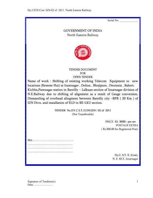
Serial No. _____________<br />
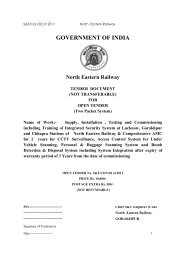
<strong>GOVERNMENT</strong> <strong>OF</strong> <strong>INDIA</strong><br />
<strong>North</strong> <strong>Eastern</strong> <strong>Railway</strong><br />
TENDER DOCUMENT<br />
FOR<br />
OPEN TENDER<br />
Name of work : Shifting of existing working Telecom Equipment to new<br />
locations (Remote Hut) at Izzatnagar , Dohna , Bhojipura , Deorania , Baheri,<br />
Kichha,Pantnagar station in Bareilly – Lalkuan section of Izzatnagar division of<br />
N.E.<strong>Railway</strong> due to shifting of alignment as a result of Gauge conversion,<br />
Dismantling of overhead alingment between Bareilly city –BPR ( 20 Km ) of<br />
IZN Divn. and installation of ELD in BE-LKU section.<br />
TENDER No.DY.C S.T./CON/IZN / 02 of 2011<br />
(Not Transferable)<br />
PRICE RS. 3000/- per set<br />
POSTAGE EXTRA<br />
( Rs.500.00 for Registered Post)<br />
M/s……………………………………..<br />
…………………………………………<br />
…………………………………………<br />
…………………………………………<br />
Dy.C. S.T. E. (Con),<br />
N. E. RLY, Izzatnagar<br />
Signature of Tenderer(s)<br />
Date…………………<br />
1
Dy.CSTE/Con/ IZN/02 of 2011 <strong>North</strong> <strong>Eastern</strong> <strong>Railway</strong><br />
IMPORTANT INFORMATIONS<br />
TENDER No.DY.C .S.T.E./CON/IZN/02 of 2011<br />
NAME <strong>OF</strong> THE WORK : As mentioned on first page.<br />
APPROXIMATE COST <strong>OF</strong> THE WORK : Rs. 39,35,674.50<br />
EARNEST MONEY: Rs. 78800.00<br />
PLACE, DATE & TIME <strong>OF</strong> GETTING,SUBMITTING & OPENING <strong>OF</strong> THE TENDER DOCUMENT:<br />
Place : Office of the Date Time<br />
Getting Dy.C.S.T.E./CON/N.E.RAILWAY/Lucknow 15.12.11 Up to 13.00 Hrs.<br />
Submission As per para 1.4 of page No. 3 or 1.2.1 of 16.12.11 Up to 14.30 Hrs.<br />
Opening page No. 6 16.12.11 At 15.00 Hrs.<br />
CONSIGNEE: - SSE / CON / TELE / BADSHAH NAGAR/N.E.Rly. at BAREILLY CITY.<br />
FIELD <strong>OF</strong>FICER (Engineer In Charge) : Dy.CSTE / Con / NERly. / Izzatnagar or his nominee.<br />
COMPLETION PERIOD: 03 MONTHS<br />
ADDRESS <strong>OF</strong> CORRESPONDENCE:<br />
Prior to award of the contract: The DY.Chief Sig. & Telecom. Engineer/Con/ N.E.<strong>Railway</strong><br />
/Izzatnagar -273012 or his successors / nominee (whose address will be indicated in due course).<br />
After the award of the contract: The Dy. Chief Sig. & Telecom. Engineer / Con / N.E.<strong>Railway</strong> /<br />
Izzatnagar or his successors/nominee (whose address will be intimated in due course).<br />
Signature of Tenderer(s)<br />
Date…………………<br />
2
Dy.CSTE/Con/ IZN/02 of 2011 <strong>North</strong> <strong>Eastern</strong> <strong>Railway</strong><br />
INSTRUCTIONS TO TENDERER(S) FOR SUBMITTING TENDER DOCUMENTS AFTER<br />
DOWNLOADING FROM WEBSITE GIVEN BELOW.<br />
1.0 INSTRUCTIONS :<br />
1.1 Tenderer(s) who are submitting downloaded (from website) tender documents<br />
must enclose with the tender form a non-refundable prescribed tender fee of in form of<br />
Bank Draft issued by any Nationalized Bank in favour of FA&CAO/Construction, <strong>North</strong><br />
<strong>Eastern</strong> <strong>Railway</strong>, Gorakhpur. Tender offers not accompanying with the requisite tender fee<br />
shall be summarily rejected.<br />
1.2 A certified copy of original tender document is available in the tender section of<br />
Dy.CSTE/Con, N. E. <strong>Railway</strong>, Lucknow, which may be seen on any working day during<br />
prescribed period for sale of tender form. Tenderer(s) on award of contract will have to enter<br />
into agreement with <strong>Railway</strong> in format of above mentioned original tender documents.<br />
Tenderer(s) shall not have any right/claim to insist on signing of contract agreements in<br />
format on which tender document were submitted by him after downloading from website.<br />
1.3 If during process of tender finalization, it is detected that tenderer has submitted<br />
tender documents after making any changes / additions / deletions in the tender documents<br />
downloaded from website, then, the earnest money deposited by the tenderer shall be<br />
forfeited by the <strong>Railway</strong>. Further, if after award of contract, it is detected that tenderer has<br />
submitted tender documents after making any changes/additions/deletions in the tender<br />
documents downloaded from website then <strong>Railway</strong> will take action to remove the contract<br />
from the work in terms of clause 62 of GCC 1999 and initiate such further legal action against<br />
contractor as it considered necessary.<br />
1.4 Tender must be submitted in the tender document (non- transferable) supplied by<br />
the <strong>Railway</strong>, along with other relevant enclosure in a sealed cover super-scribed “Tender No<br />
as mentioned in page no. 2” and must be deposited in the special Box allotted for this purpose<br />
in the Dy. Chief Signal & Telecommunication Engineer/Construction/ N.E.<strong>Railway</strong> /<br />
Lucknow-226001 or sent by Registered Post / Speed Post to the Dy.Chief Signal &<br />
Telecommunication Engineer/Construction / N. E. <strong>Railway</strong>/ Lucknow-226001 so as to reach<br />
the office not later than 14:30Hrs of prescribed date. The Tender box will be sealed at 14-30<br />
hrs of prescribed date. The tender will be opened on prescribed date at 15-00 hrs. If the date<br />
of opening happens to be holiday/bandh, the tender will be opened at 15-00 Hrs on the next<br />
working day.<br />
Signature of Tenderer(s)<br />
Date…………………<br />
3
Dy.CSTE/Con/ IZN/02 of 2011 <strong>North</strong> <strong>Eastern</strong> <strong>Railway</strong><br />
1. NAME <strong>OF</strong> WORK : AS CAPTIONED<br />
2. SCOPE <strong>OF</strong> WORK :<br />
SECTION – I<br />
PREAMBLE<br />
The work covered in this tender is for Shifting of existing working Telecom Equipment to<br />
new locations (Remote Hut) at Izzatnagar , Dohna , Bhojipura , Deorania , Baheri,<br />
Kichha,Pantnagar station in Bareilly – Lalkuan section of Izzatnagar division on N.E.<strong>Railway</strong><br />
due to shifting of alignment as a result of Gauge conversion, Dismantling of overhead alingment<br />
between Bareilly city –BPR ( 20 Km ) of IZN Divn. and installation of ELD in BE-LKU section.<br />
2.1 The <strong>Railway</strong> shall supply HDPE pipe<br />
2.2 The contractor shall be required to carry out all the remaining works .<br />
2.3 All the work shall be executed as per details given in technical supplement/specification.<br />
3. TENDER BID:<br />
Tender bid shall be submitted in sealed cover. The details are given in Para 1.2 of “instructions to<br />
tenders & conditions of tendering ” (section II chapter I ).<br />
4. ELIGIBILITY CRITERIA: Already specified at page No. 2 .<br />
5. LAST DATE <strong>OF</strong> SUBMISSION: Already specified at page No. 2<br />
6. DATE <strong>OF</strong> OPENING <strong>OF</strong> TENDER: Already specified at page No. 2<br />
7. COMPLETION PERIOD <strong>OF</strong> THE WORK: Already specified at page No. 2<br />
8. THE LIST <strong>OF</strong> ADDRESS TO WHICH CORRESPONDENCE AND DOCUMENTS RELATING<br />
TO THE CONTRACT SHOULD BE SENT: Already specified at page No. 2<br />
9. SUPPLY <strong>OF</strong> MATERIALS:<br />
All materials shall be supplied by the contractor at consignee’s store. Consignee has already been<br />
specified at Page N0.2. These stores will be issued to the contractor from consignee’s store. The<br />
contractor will transport the materials by their own means free of charge from consignee’s store to<br />
the site .<br />
10 SPECIFICATION/DRAWINGS:<br />
Reference of specifications / drawings of the important equipment, components and other materials<br />
required for the execution of the contract are given in technical supplement. The work shall be<br />
executed in compliance with the entire technical requirement given there.<br />
11. SCHEDULE <strong>OF</strong> QUANTITIES:<br />
The schedule of quantities for supplies and various works are indicated in schedule of work and given<br />
as enclosure to the preamble. The tenderer is advised to quote for all items.<br />
12. STORE To BE SUPPLIED BY RAILWAYS: (1) Quad Cable, (2) HDPE duct.<br />
13. INSPECTION <strong>OF</strong> MATERIALS:<br />
Materials to RDSO & TEC Specification will be inspected by RDSO as per their latest inspection<br />
Policy.<br />
The Firm should have valid type approval test for the items on the date of opening of tender.<br />
Signature of Tenderer(s)<br />
Date…………………<br />
4
Dy.CSTE/Con/ IZN/02 of 2011 <strong>North</strong> <strong>Eastern</strong> <strong>Railway</strong><br />
Name of the work :- AS CAPTIONED<br />
Approximate cost of the work ;- As per page No.2<br />
To<br />
The President of <strong>India</strong><br />
Acting through the DY.Chief Signal & Telecommunication Engineer (Construction)<br />
N. E. <strong>Railway</strong>, Izzatnagar – .<br />
1.0 I/We ___________________________________ have read the various conditions to the<br />
tender attached hereto and hereby agree to abide by all the said conditions. I/We also here<br />
by agree to keep this tender open for acceptance for a period of at least 120 (One hundred and<br />
twenty) days from the date fixed for opening of the same and in default thereof I/We will be<br />
liable for forfeiture of my/our earnest money . I/We offer to do the work for Dy.Chief Signal<br />
& Telecom. Engineer (Construction) / N. E. <strong>Railway</strong> at the rate quoted in the attached<br />
schedule and hereby bind myself/ ourselves to complete the work in all respect within four<br />
months from the date of issue of letter of acceptance of the tender.<br />
2.0 I/We _______________________________ also hereby agree to abide by the General Conditions<br />
of Contract of N.E.<strong>Railway</strong> edition 1999 with latest amendment. (although meant for use in<br />
connection with Civil Engineering Work but shall also be applicable in this<br />
contract),Instructions to tenderers and conditions of tender & Contract, Special conditions of<br />
tender & contract and to carryout the work according to the specification for materials and<br />
works laid down by railway for the present contract.<br />
3.0 I/We have been enclosed the requisite Earnest money in form of ______________in original<br />
issued from __________________ in favour of FA&CAO / Con / N. E. <strong>Railway</strong>, Gorakhpur<br />
and is valid up to ___________________________<br />
4.0 I/We enclosed herewith receipt in original from the Divisional Cashier /con / N. E. <strong>Railway</strong>,<br />
Gorakhpur. It’s particular are :-<br />
Receipt No. & Date of deposit.<br />
Amount<br />
Once the acceptance of the tender is communicated to me/us, a legal and enforceable<br />
contract comes into being. If in accordance with the letter of acceptance, I/We fail to<br />
commence work within the period stipulated in the acceptance letter and fail to execute the<br />
formal agreement, I/We shall be liable for breach of the contract and the consequences of the<br />
breach of any of the conditions of the contract entitling the <strong>Railway</strong> Administration to<br />
have work/job executed at the risk and cost of mine /ours and to claim the extra cost /<br />
expenditure sustained by the <strong>Railway</strong> Administration.<br />
Tenderer(s) full Address:<br />
Signature of Witnesses<br />
1. _________________<br />
Signature of the tenderer(s)<br />
Date___________________<br />
Stamp:………………………<br />
2.__________________<br />
Signature of Tenderer(s)<br />
Date…………………<br />
5
Dy.CSTE/Con/ IZN/02 of 2011 <strong>North</strong> <strong>Eastern</strong> <strong>Railway</strong><br />
(TENDER FORM SECOND SHEET)<br />
INSTRUCTIONS TO TENDERERS AND CONDITIONS <strong>OF</strong> TENDER & CONTRACT<br />
1.1 TENDER DOCUMENTS : The documents forming the ‘Complete Tender’ (which is<br />
deemed to be part of the contract) consist of the following:<br />
(a) Tender forms (First and Second Sheet)<br />
(b) Special conditions of Tender & Contract.<br />
(c) Technical specifications of Tender & Contract.<br />
(d) Schedule of work with approximate quantities.<br />
(e) “Regulations for Tender and contract”. “General condition of contract” of N.<br />
E. <strong>Railway</strong> Edition – 1999. (although meant for use in connection with Civil<br />
Engineering Works, shall also be applicable for this contract) hereinafter called<br />
General Condition of Contract, and “<strong>India</strong>n <strong>Railway</strong> Code for the Engineering<br />
Department” with up-to-date corrections (not enclosed herewith).<br />
However conditions/provisions in the tender forms (First & Second Sheets) and<br />
special conditions of tender & contract and Technical Specification vide 1.1(b)<br />
& (c) above will over-ride any overlapping or conflicting conditions /<br />
provisions given in these documents.<br />
(f) <strong>India</strong>n <strong>Railway</strong> Telecommunication Manual with latest corrections (not<br />
enclosed herewith).<br />
(g) All general and detailed drawings pertaining to this work which will be<br />
issued by the Engineer-in-charge or his representative from time to time with<br />
all changes and modifications.<br />
Note : The documents which are not enclosed herewith can be seen in the office of<br />
DY.Chief Signal & Telecommunication Engineer / Construction / N. E. <strong>Railway</strong> /<br />
Lucknow, on any working day during office hours.<br />
1.2 SUBMISSION <strong>OF</strong> TENDER:<br />
1.2.1 Tender must be submitted in the tender document (non- transferable) supplied<br />
by the <strong>Railway</strong>, along with other relevant enclosure in a sealed cover super scribed<br />
“Tender No as mentioned in page no. 2” and must be deposited in the special Box allotted<br />
for this purpose in the office of the Dy. Chief Signal & Telecommunication Engineer /<br />
Construction / N.E.<strong>Railway</strong> / Lucknow-226001 or sent by Registered Post / Speed<br />
Post to the Dy.Chief Signal & Telecommunication Engineer / Construction / N. E.<br />
<strong>Railway</strong> / Lucknow-226001 so as to reach the office not later than 14:30 Hrs of<br />
prescribed date. The Tender box will be sealed at 14-30 hrs of prescribed date. The<br />
tender will be opened on prescribed date at 15-00 hrs. If the date of opening happens<br />
to be holiday/ bandh, the tender will be opened at 15-00 Hrs on the next working day.<br />
1.2.2 Tender documents (non-transferable ) can be purchased and submitted through<br />
authorized agents of the tenderer.<br />
1.2.3 <strong>Tenders</strong> submitted by the tenderers who have not purchased the tender<br />
documents themselves or through their agents, tenders not accompanied by<br />
earnest money, tenders from agents without letter of authority from the<br />
Principals will be summarily rejected.<br />
1.2.4 Telex or incomplete offer will be summarily rejected.<br />
1.2.5 No rates should be quoted with fraction of rupees.<br />
Signature of Tenderer(s)<br />
6<br />
Date…………………
Dy.CSTE/Con/ IZN/02 of 2011 <strong>North</strong> <strong>Eastern</strong> <strong>Railway</strong><br />
1.2.6 Tender documents submitted by a tenderer shall become the property of<br />
<strong>Railway</strong> and the railway shall have no obligation to return the same to the<br />
tenderer(s).<br />
1.2.7 The tender shall be submitted in sealed envelope. The envelope should bear the<br />
tender number, its description and date of closing/opening.<br />
1.2.8 The Tender shall contain the offer letter and the price of each item quoted<br />
exactly according to the Performa and schedule of requirements and sealed.<br />
Any multiple offer without technical alternatives will make the offer/tender<br />
invalid and <strong>Railway</strong> will summarily reject such tender / offer.<br />
1.2.9 COMPLIANCE TO TENDER CONDITIONS, SPECIFICATION AND<br />
DRAWINGS :-<br />
The equipment offered shall be in accordance with the drawings and<br />
specifications. Details of variation from the drawings and specifications, if<br />
any, should be clearly indicated and in such an event, a certificate from the<br />
users must be furnished to the effect that the product offered performs the<br />
requisite functions satisfactorily, & is an alternative acceptable in one or more<br />
other countries. The name of users in those foreign countries should also be<br />
indicated.<br />
1.2.10 The tenderer shall indicate paragraph by paragraph for each section of the<br />
tender document that either his tender complies in every respect with the<br />
requirements of each clause and sub-clause or if not, precisely how they differ<br />
from the requirements of the tender. In later case, “the tenderer shall enclose<br />
a separate statement as per Proforma given, indicating only the deviations for<br />
any clause or sub-clause of General Conditions of Contract, Special conditions<br />
of Contract, Instructions to tenderer(s) and conditions of tendering, Technical<br />
specification, etc. which he proposes with” details justifications for deviations<br />
proposed. The purchaser, reserves the right to accept or reject these deviations<br />
and his decision thereon shall be final.<br />
1,2.11 The tenderer shall sign and stamp each and every page of the tender<br />
documents in token of his/their having read, understood, agreed and complied<br />
the same, and to this effect he shall submit in writing “I/We hereby confirm<br />
that I/We agree to comply all the conditions of the complete Tender<br />
mentioned in Para 1.1 above of this tender document”, along-with his offer,<br />
without which his/their offer is liable to be rejected.<br />
1.2.12 Tenderer(s) shall also sign at each and every page/paper of all other documents<br />
/ manuals / Literatures / drawings / sketches / leaflets etc., to be submitted by<br />
them along with their offer, in token of having been understood and owned<br />
such submission fully, by the tenderer(s) without which his/their tender is<br />
liable to be rejected.<br />
SIGNING <strong>OF</strong> TENDER :<br />
All offers shall be either type written or written neatly in indelible ink. Each<br />
page of the offer must be numbered consecutively. A reference to total number<br />
Signature of Tenderer(s)<br />
Date…………………<br />
7
Dy.CSTE/Con/ IZN/02 of 2011 <strong>North</strong> <strong>Eastern</strong> <strong>Railway</strong><br />
of pages comprising the offer must be made at the top right hand corner of the<br />
top page.<br />
All copies of the tender paper shall be signed in ink by the tenderer, on each<br />
page including closing page, in token of his having studied the tender papers<br />
carefully.<br />
1.2.13 The intending tenederer is advised to study the tender papers carefully. Any<br />
submission of a quotation by the tenderer shall be deemed to have been done<br />
after a careful study and examination of these documents with full<br />
understanding of the implication thereof. These conditions and specifications<br />
shall be deemed to have been accepted unless otherwise, specifically<br />
commented upon by the tenderer in his quotation. Failure of adhere to anyone<br />
or all these instructions may render his offer liable to be ignored without any<br />
reference.<br />
1.2.14 Should a tenderer find discrepancies or omission from the drawing or any of<br />
the tender papers or he has any doubt to their meaning, he should at once<br />
notice the <strong>Railway</strong> who may send a written clarification to all tenderer(s).<br />
1.2.15 ADDRESS FOR COMMUNICATION :-<br />
Tenderer shall indicate his postal address, telephone numbers, telegraphic<br />
address, if any, and telex/fax numbers. Any communication sent to the<br />
tenderer(s) at his said address, shall be deemed to have reached timely, not<br />
withstanding the fact that the communication could not reach the tenderer at<br />
all or in time because of any inaccuracy or defect in the said address. Any<br />
change thereof shall be advised to <strong>Railway</strong> promptly.<br />
1.3 EARNEST MONEY:<br />
1.3.1 The tenderer(s) is/are required to deposit with the Divisional Cashier / Con. /<br />
N. E. <strong>Railway</strong>/Gorakhpur in favour of FA&CAO/CON/ N.E. RLY/Gorakhpur a<br />
sum prescribed money as Earnest Money, and the receipt obtained thereof<br />
should be enclosed with the tender as a proof of the deposit of the requisite<br />
Earnest Money<br />
1.3.2 The Earnest Money can also be deposited in any of the following forms in<br />
favour of FA&CAO/CON/N. E. RAILWAY/Gorakhpur, in lieu of Cash. In<br />
such case the validity / currency (if applicable) should be at least three months<br />
beyond the date of validity of offer.<br />
(i) Deposit Receipt, Pay Order, and Demand Draft. These forms of Earnest<br />
Money should be either of The State Bank of <strong>India</strong> or any other Nationalized<br />
Banks. No confirmatory advice from the Reserve Bank of <strong>India</strong> will be<br />
necessary.<br />
(ii) Deposit Receipt executed by the scheduled banks (other than the State<br />
Bank of <strong>India</strong> and 8 Nationalized Bank) approved by the Reserve Bank of <strong>India</strong><br />
for the purpose.<br />
(iii) Deposit Receipt tendered by the scheduled bank which have not been<br />
approved by Reserve Bank of <strong>India</strong> for the purpose provided :<br />
Signature of Tenderer(s)<br />
Date…………………<br />
8
Dy.CSTE/Con/ IZN/02 of 2011 <strong>North</strong> <strong>Eastern</strong> <strong>Railway</strong><br />
a) The bond in question is countersigned by any of the approved bank<br />
(including the State Bank of <strong>India</strong>) whereby the later undertake full<br />
responsibility to indemnify the N. E. <strong>Railway</strong> in case of default.<br />
or<br />
b) The bank concerned lodged with the Reserve Bank of <strong>India</strong> requisite<br />
securities , namely cash deposits of Government securities in respect of<br />
the guarantees to be executed or deposit receipts to be tendered by it.<br />
Apart from the above provisions, prior concurrence of the Reserve<br />
Bank of <strong>India</strong>, in writing should be necessary before accepting Deposit<br />
Receipts under (iii) (a), (b).<br />
Government securities (stock certificates, bearer bonds, promissory<br />
notes, cash certificate etc.) will not be accepted.<br />
1.3.3 Tender un accompanied by the requisite earnest money will be summarily<br />
rejected. If the deposit receipt for earnest money is not in any of the<br />
prescribed forms as stipulated in Para 1.3.2 above, the tender will be<br />
considered as un accompanied by requisite earnest money, and hence will be<br />
summarily rejected.<br />
1.3.4 The tenderer(s) shall hold the offer open for a period of at least 120 days (One<br />
Hundred Twenty days) from the date fixed for opening the same. It is<br />
understood that the tender documents have been sold/issued to the tenderer in<br />
consideration of the stipulation on his part that after submitting his tender. He<br />
will not resile from his offer or modify the terms and conditions thereof in a<br />
manner not acceptable to the <strong>Railway</strong>. Should the tenderer fail to observe or<br />
comply with the foregoing stipulation the whole amount of Earnest Money shall<br />
be liable to be forfeited by the <strong>Railway</strong>.<br />
1.3.5 The earnest money will be refunded to the unsuccessful tenderer/ tenderer(s)<br />
within a reasonable time but the railway shall not be responsible for any loss or<br />
depreciation that may happen to the security for due performance to keep the<br />
offer open, or to the earnest money, while in their possession nor be liable to pay<br />
interest thereon. The earnest money deposit of the successful tenderer/<br />
tenderer(s) will be retained towards to security deposit for the due and faithful<br />
fulfillment of the contract, but shall be forfeited without prejudice to any other<br />
rights or remedies, if the, contractor/ contractors fail to execute the agreement<br />
bond or to start the work within the periods stipulated .<br />
Note: Earnest Money in the form of Guarantee Bond shall not be accepted.<br />
Security Deposit<br />
1.4.1 The Earnest Money deposited by the successful tenderer with his tender will<br />
be retained by the <strong>Railway</strong> as part of security deposit for the due and faithful<br />
fulfillment of the contract by the contractor. The full security deposit for the<br />
work will be calculated as provision of GCC applicable as with up to date<br />
corrections if any. The balance amount over and above amount of earnest<br />
money may be deposited by the contractor in cash with the Chief Cashier,<br />
<strong>North</strong> <strong>Eastern</strong> <strong>Railway</strong>, Gorakhpur or may be recovered from the contractor’s<br />
Signature of Tenderer(s)<br />
Date…………………<br />
9
Dy.CSTE/Con/ IZN/02 of 2011 <strong>North</strong> <strong>Eastern</strong> <strong>Railway</strong><br />
“on account” bills at the rate of 10% of the bill amount till the such time<br />
amount recovered plus amount of earnest money already adjusted becomes<br />
equal to the full requisite security deposit of 5% of the contract value.<br />
1.4.2 Security Deposit will be recovered only from the running bills of the contracts<br />
and no other mode of collecting security deposit such as Security Deposit in<br />
the form of instruments like Bank Guarantee, Fixed Deposit etc. shall be<br />
accepted towards security deposit.<br />
1.4.3 No interest will be payable upon the Earnest Money and Security Deposit or<br />
amounts payable to the contractor under the contract.<br />
1.4.4 The railway shall be entitle to deduct from the said deposit any loss or<br />
damages which the <strong>Railway</strong> may be put to by reasons of any act of default on<br />
the part of the contractor and may call upon the contractor to replenish and<br />
maintain a deposit as its original limit by making further deposits. In the even<br />
of the contractor failing to make the deposit within time and the manner<br />
aforesaid, the railway shall be entitled to cancel the contract and forfeit the<br />
security amount deposited by the contractor.<br />
1.4. The security deposit referred to above shall be forfeited to the <strong>Railway</strong> in the<br />
event of any breach on the part of the contractor of the terms and conditions<br />
of this contract without prejudice to the <strong>Railway</strong>s right to rescind the contract<br />
and other rights and remedies warranted by law.<br />
1.4.6 The security deposit shall be repaid on the expiry of the warranty period on<br />
receipt of the certificate from the Engineer concerned to the effect that work<br />
has been satisfactorily completed in all respects within the stipulated period<br />
mentioned therein and no defects have been noticed.<br />
1.5 BRIEF DESCRIPTION <strong>OF</strong> THE WORK: As captioned vide page No. 2.<br />
(a) O.F.C./Quad cable ( as the case may be ) & (b) HDPE duct will be supplied<br />
by the <strong>Railway</strong><br />
(b) For exact item wise details, schedule of work may be referred. However,<br />
any further clarifications thereof can be obtained from the office of<br />
Dy.Chief Signal & Telecommunication Engineer /con / N. E.<br />
<strong>Railway</strong>/Lucknow , well in advance.<br />
1.6 LOCAL CONDITIONS :-<br />
1.6.1 It will be imperative on each tenderer to fully acquaint himself with all the<br />
local conditions and factors which would have any effect on the performance<br />
of the contract and cost of the stores. The purchaser shall not entertain any<br />
request for clarifications from the tenderer regarding such local conditions. No<br />
request for the change of price, or time schedule of delivery of stores shall be<br />
entertained after the offer is accepted by the purchaser on account of any local<br />
condition or factor.<br />
1.6.2 In the event of the tenderer desiring to have a field survey before furnishing<br />
his quotations, he may apply to railways for permission in this regard. Such<br />
permission will be given in writing by the railways but the expenses in this<br />
regard will be borne by the tenderer completely.<br />
Signature of Tenderer(s)<br />
Date…………………<br />
10
Dy.CSTE/Con/ IZN/02 of 2011 <strong>North</strong> <strong>Eastern</strong> <strong>Railway</strong><br />
1.6.3 Before submitting tender the tenderer(s) is/are advised to inspect the proposed<br />
site of work and fully acquaint himself/themselves with the site conditions,<br />
working hours, stacking space for materials, approach roads, pathways<br />
available etc. and all relevant items connected with the execution of the work.<br />
No claim shall be entertained at a later stage by the railway on such grounds<br />
from the contractor(s).<br />
1.6.4 DRAWING(S) FOR THE WORK: Drawing(s) related for the work can be seen<br />
in the office of the Chief Signal & Telecomm Engineer / con / N. E.<br />
<strong>Railway</strong>/Gorakhpur at any working day during office hours. The drawings are<br />
tentative and <strong>Railway</strong> reserves the right to make changes in plans if<br />
considered necessary and no compensation in any form will be admissible on<br />
this account. The contractor(s) will have to execute the work as per final plans<br />
at the rates quoted by him/them.<br />
1.7 QUALIFYING CRITERIA :- As mentioned at Page No. 2 along with the following<br />
notes.:<br />
(i) Certificate from private individuals for whom such works are executed/being<br />
executed should not be accepted.<br />
(ii) Tenderer must submit documentary proof and credentials duly attested in<br />
support of Eligibility criteria along with tender document, failing which no<br />
further correspondence shall be made/entertained and no opportunity shall be<br />
given after opening of tender. However, <strong>Railway</strong> reverses the right to<br />
accept/reject the tender.<br />
(iii) In case of submission of any fake credentials by the tenderer, <strong>Railway</strong> reserves<br />
the right to forfeit earnest money.<br />
1.8. Engineering Organisation :<br />
(The tenderer should have at least one graduate Engineer and two experienced<br />
supervisors (Diploma Holders) having 5 years experience in the relevant field,<br />
supported by at least 5 nos. of artisan staff like Telecom. fitters. Details of which will<br />
be furnished by them along-with the tender.<br />
1.8.1 Construction Machinery :- The firm should have minimum construction<br />
machinery, Tools and plants, vehicle etc. Details of which will be furnished by<br />
them along with the tender<br />
1.8.2 Test and measuring instruments, special tools and installation material.<br />
(a) Special tools required for installation and maintenance of all the<br />
equipment shall be arranged by the tenderer in adequate quantities. All<br />
installation materials for commissioning of the system shall be provided by<br />
the tenderer.<br />
(b) All tests and measuring instruments and other arrangements required for<br />
all the acceptance tests shall be provided by the tenderer free of cost.<br />
1.8.3 Financial Criteria :- Audited Balance Sheet and Income statement of just<br />
concluded year.<br />
Signature of Tenderer(s)<br />
Date…………………<br />
11
Dy.CSTE/Con/ IZN/02 of 2011 <strong>North</strong> <strong>Eastern</strong> <strong>Railway</strong><br />
1.8.4 Equipments: The tenderer shall identify the sources from which the<br />
equipment to be supplied under this tender will be obtained.<br />
1.9 SYSTEM PERFORMANCE GUARANTEE.<br />
1.9.1 Since the design of the system to achieve the end objective shall be checked<br />
and confirmed by the contractor and the supply of the materials will be<br />
according to this system design, the tenderer shall give unqualified and<br />
unconditional guarantee that when the equipment supplied by him is<br />
installed and commissioned at site , it shall achieve desired objective. In the<br />
event of performance of the system when installed not complying the end<br />
objective or with the specifications , he shall provide further inputs to enable<br />
the <strong>Railway</strong>s to realize the end objectives with full compliance of the<br />
specifications contained in these documents. No additional payment will be<br />
made to the contractor for supply of any additional goods and services required<br />
in this regard.<br />
1.9.2 This certificate in the Proforma given in Annexure shall accompany the final<br />
offer. Absence of this certificate which will form part of the agreement will<br />
disqualify the tenderer automatically.<br />
1.9.3 WARRANTY. The contractor shall warrant that every equipment/ software<br />
furnished shall be free from defects and faults in design, material,<br />
workmanship and manufacture and shall be of highest grade and consistent<br />
with the established and generally accepted standards for goods of the type<br />
ordered. The warranty of the product shall be for a period of 12 months from<br />
the date of Final Acceptance certificates. During warranty period system<br />
should be available for 98% (99% during maintenance period) of Time at least.<br />
1.9.4 If the tenderer proposes to buy any equipment from other supplier / source,<br />
document indicating their willingness to supply the equipment and provide<br />
technical support to the tenderer that may be required during installation ,<br />
commissioning and warranty andlater on directly to the railways and also<br />
performance guarantee bond of the equipment for minimum twelve<br />
months(from the date of commissioning ) shall be included in the tender.<br />
1.10 PARTNERSHIP DEEDS, POWER <strong>OF</strong> ATTORNEY FOR PARTNER(S)/AGENT(S).<br />
1.10.1 The tenderer shall clearly specify whether the Tender is submitted on his own<br />
behalf or on behalf of partnership concern. If the tender is submitted on behalf<br />
of partnership concern he should submit the certified copy of partnership deed<br />
and power of Attorney to sign the tender documents on behalf of the<br />
partnership concern along with the tender. If these documents are not<br />
enclosed along with the tender documents, the tender will be treated as having<br />
been submitted by individual signing the documents. The <strong>Railway</strong> will not be<br />
bound by any power of Attorney granted by the tenderer or by changes in the<br />
composition of the firm made subsequent to the execution of the contract. It<br />
may, however recognize such power of attorney and changes after obtaining<br />
proper legal advice, the cost of which will be chargeable to the contractor. If<br />
the tender is on behalf of the company, it should be signed by a duly<br />
Signature of Tenderer(s)<br />
Date…………………<br />
12
Dy.CSTE/Con/ IZN/02 of 2011 <strong>North</strong> <strong>Eastern</strong> <strong>Railway</strong><br />
authorized person on behalf of the company. Non-compliance with any of the<br />
conditions set forth herein above is liable to result in the tender being rejected.<br />
1.10.2 The tenderer whether sole proprietor, a limited company or a partnership firm,<br />
if any, want to act through agents or individual partner/partners should submit<br />
along with the tender or at a later stage a power of attorney duly stamped and<br />
authenticated by a Notary public or by a Magistrate in favour of the specific<br />
person(s) whether he/they be partner /partners of the firm or any other<br />
person(s) specifically authorising him/them to sign the agreement, receive<br />
money, witness measurement, sign measurement book, compromise, settle,<br />
relinquish any claim or claims preferred by the firm and sign “No claim<br />
certificate” and refer all or any disputed items to arbitration<br />
1.11 EMPLOYMENT, PARTNERSHIP, SHARE HOLDER ETC. <strong>OF</strong> RETIRED<br />
RAILWAY EMPLOYEE:<br />
1.11.1 Should tenderer be a retired Engineer of the gazetted rank or any other<br />
gazetted officer working before his retirement whether in the executive or<br />
Administrative capacity or whether holding a pensionable post or not in the<br />
Signal & Telecommunication Engineering Department of any of the <strong>Railway</strong><br />
owned and/or administered by the President of <strong>India</strong> for the time being or<br />
should tenderer being a partnership firm have as one of its partners a retired<br />
Signal & Telecommunication Engineer or a retired Gazetted Officer as<br />
aforesaid or should a tenderer being an incorporated company have any such<br />
retired Signal & Telecommunication Engineer or retired gazetted officer as<br />
one of the Directors, or should a tenderer have in his company any retired<br />
Signal & Telecommunication Engineer or retired gazetted officer as aforesaid,<br />
the full information as to the date of retirement of such engineer or gazetted<br />
officer from the said service and, in case where such Signal &<br />
Telecommunication Engineer or officer had not retired from Govt. service at<br />
least two years prior to the date of the submission of the tender, as to whether<br />
permission for taking such contract or, if the contractor be a partnership firm<br />
or any incorporated company to become a partner or director as the case may<br />
be or to take employment under the contractor has been obtained by the<br />
tenderer or the Signal & Telecommunication Engineer or the officer or his<br />
agent authorized by him in this behalf, shall be clearly stated in writing at the<br />
time of submitting the tender. Tender without the information’s above<br />
referred to or a statement to the effect that no such retired Signal &<br />
Telecommunication Engineer or retired Gazetted officer is so associated with<br />
the tenderer, as the case may be, shall be rejected.<br />
1.11.2 Should a tenderer or contractor being an individual on the list of approved<br />
contractor, have relative employed in Gazetted capacity in any department of<br />
the N. E. <strong>Railway</strong>, or in the case of partnership firm or company incorporated<br />
under the <strong>India</strong>n Company Law, should a partner or a relative of the partner<br />
or a shareholder or a relative of a shareholder be employed in gazetted<br />
capacity in any department of the N. E. <strong>Railway</strong>, the authority inviting tender<br />
Signature of Tenderer(s)<br />
Date…………………<br />
13
Dy.CSTE/Con/ IZN/02 of 2011 <strong>North</strong> <strong>Eastern</strong> <strong>Railway</strong><br />
shall be informed of the fact at the time of submission of tender failing which<br />
the tender may be rejected or if such fact subsequently comes to light the<br />
contract may be rescinded in accordance with the provisions in clause 62 of<br />
the General Condition of Contract.A declaration to this effect should be signed<br />
and enclosed with the tender.<br />
1.12 ERRORS, OMISSION & DISCREPENCIES: -The contractor(s) shall not take any<br />
advantages of any mis-interpretation of the conditions due to typing or any<br />
other error and if in doubt, shall bring it to the notice of the Engineer, without<br />
delay. In case of any contradiction only the printed rules, and books should be<br />
followed and no claim for the mis-interpretation shall be entertained<br />
1.13 ACCEPTANCE/REJECTION <strong>OF</strong> TENDER(S):<br />
1.13.1 The authority competent for the acceptance of this tender does not bind<br />
himself to accept the lowest or any other tender nor does he undertake to<br />
assign reasons for declining to consider any particular tender or tenders. No<br />
tenderer/(s) shall demand any explanation of the cause of rejection of his/their<br />
tender. No correspondence will be entertained with the tenderer(s) in respect<br />
of the rejection of any or all tenders.<br />
1.13.2 The tender containing erase and/or alterations of the tender<br />
documents are liable to be rejected. Any corrections made by the tenderer(s)<br />
in his/their entries must be attested.<br />
1.13.3 If a tenderer deliberately gives/tenders wrong information/s in his/their tender<br />
or creates/create circumstances for the acceptance of his/their tender, the<br />
railway reserves the right to reject such tender at any stage.<br />
1.13.4 If a tenderer expires after the submission of his tender or after the acceptance<br />
of his tender, the railways shall deem such tender as cancelled. If a partner of<br />
the firm expires after the submission of their tender or after the acceptance of<br />
their tender the railway shall deem such tender as cancelled unless the firm<br />
retains its character.<br />
1.14 EXECUTION <strong>OF</strong> CONTRACT AGREEMENT: The successful tenderer(s) shall be<br />
required to execute a contract agreement (herein after called C.A)with the<br />
railway for carrying out the work according to condition of Tender &<br />
Contract, Special Condition of Tender & Contract, Specification of Tender,”<br />
General Conditions of Contract”, edition-1999 with latest amendment of N. E.<br />
<strong>Railway</strong> (which shall also be applicable in this work, although meant for use in<br />
connection with Civil Engineering Works) and Schedule of work after<br />
depositing the required Security Deposit in terms of clause No.1.4 .<br />
1.15 DOCUMENTS TO ACCOMPANY THE <strong>OF</strong>FER : The following documents shall<br />
invariably accompany the offer, failing which the offer can be treated as<br />
invalid and liable to be summarily rejected without any correspondence with<br />
the firm. Hence the firm is well advised to ensure that all the minimum<br />
documents, as laid down hereunder are attached with their offer:-<br />
1.15.1 Earnest money amount drawn in favour of the FA & CAO / CON / N. E. Rly.<br />
Gorakhpur<br />
Signature of Tenderer(s)<br />
Date…………………<br />
14
Dy.CSTE/Con/ IZN/02 of 2011 <strong>North</strong> <strong>Eastern</strong> <strong>Railway</strong><br />
1.15.2 Tender documents including prices & schedule duly signed and stamped in<br />
each page.<br />
1.15.3 Documents in support of financial solvency.(Solvency certificate from any<br />
Nationalized Bank ).<br />
1.15.4Clause wise compliance statement of technical specification/special conditions<br />
etc. with documentary support.<br />
1.15.5 Details of technical staff to be deployed for this project with their name,<br />
designation, Qualification and experience.<br />
1.15.6 Testimonials / Credentials / Documentary evidence and performance record in<br />
support of satisfactory performance of the equipment supplied and for<br />
satisfactory completion of the project / work executed and any other relevant<br />
information for the last five years. The firm should summarily submit list of<br />
works carried out, which are similar to the present work in the tender<br />
document.<br />
1.15.7 As the work is of special nature, requiring highly skilled technical expertise,<br />
the firm is required to establish that they possess the requisite skill, technical<br />
expertise, technical and skilled man power and all their equipments are of high<br />
quality, able to withstand the rigorous/intensive usage in <strong>Railway</strong><br />
Telecommunication applications.<br />
1.15.8 List of personnel, Organization available on hand and proposed to be engaged<br />
for the subject work.<br />
1.15.9 List of plant & Machinery available on hand ( own) and proposed to be<br />
inducted (own and hired to be given separately) for the subject work.<br />
Signature of Tenderer(s)<br />
Date…………………<br />
15
Dy.CSTE/Con/ IZN/02 of 2011 <strong>North</strong> <strong>Eastern</strong> <strong>Railway</strong><br />
SECTION-II ,<br />
CHAPTER – II<br />
SPECIAL CONDITIONS <strong>OF</strong> TENDER AND CONTRACT<br />
2.1 GENERAL:<br />
2.1.1 These special conditions of Tender and Contract, the technical specifications<br />
and the schedule of works of this contract in addition to the General Condition<br />
of the Contract of N. E. <strong>Railway</strong> Edition – 1999 (although meant for use in<br />
connection with Civil Engineering Works, shall also be applicable for this<br />
contract), <strong>India</strong>n <strong>Railway</strong> Code for the Engineering Department with up-todate<br />
corrections, Standard Specifications for materials and works and the<br />
<strong>India</strong>n <strong>Railway</strong> Telecommunication Manual shall govern the work to be<br />
executed.<br />
2.1.2 Where there is any conflict between these specifications and conditions (as<br />
mentioned in Para 2.1.1 above) of contract on one hand and General<br />
Conditions of Contract of <strong>North</strong> <strong>Eastern</strong> <strong>Railway</strong> on the other hand, the<br />
former shall prevail.<br />
2.1.3 Any special conditions stated by the tenderer(s) in the covering letter<br />
submitted along with the tender shall be deemed to be the part of the contract<br />
to such extant only as have explicitly been accepted by the <strong>Railway</strong>s, and<br />
incorporated in the contract agreement.<br />
2.2 DEFINATIONS AND INTERPRETATIONS<br />
2.2.1 ”Engineer” shall mean the Assistant Signal & Telecommunication Engineer<br />
(Construction) and shall include the superior officers of Signal &<br />
Telecommunication Department of the N. E. <strong>Railway</strong> i.e. Divisional Signal &<br />
Telecommunication Engineer (Construction)/Deputy Chief Signal &<br />
Telecommunication Engineers / Chief Signal & Telecommunication Engineer /<br />
Construction<br />
2.2.2 Engineer-in-charge: As specified at page No. 2. “ Engineer-in-charge” will be<br />
the in-charge for execution of this work. However railway reserves the right to<br />
change the Engineer in charge at any stage due to any reason whatsoever.<br />
2.2.3 “Site engineer” shall mean any Sr. Section Engineer/Tele of Construction<br />
Organization authorized by the Engineer-in-charge.<br />
2.3 SCOPE <strong>OF</strong> THE WORK :<br />
The scope of the work broadly includes supply of materials and execution of the work<br />
as described in details in the schedule of work, drawings and technical specifications<br />
of the tender, unless deviations if any, specifically approved by the <strong>Railway</strong>.<br />
2.4 PROGRAMME <strong>OF</strong> WORKS :-<br />
2.4.1 (a) The contractor shall have necessary resources to execute the work so that<br />
the entire work is completed within a period as mentioned in the preamble<br />
from the date of issue of Letter of Acceptance of the tender.<br />
Signature of Tenderer(s)<br />
Date…………………<br />
16
Dy.CSTE/Con/ IZN/02 of 2011 <strong>North</strong> <strong>Eastern</strong> <strong>Railway</strong><br />
(b)The Program of work to be followed is given as under:<br />
D: Date of issue of Letter of Acceptance from <strong>Railway</strong> to the<br />
Contractor.<br />
D+1/2 months Completion of supply of Scheduled materials.<br />
D+1 months Completion of 50% of Scheduled outdoor works .<br />
D+1-1/2 month Completion of 50% of remaining Scheduled outdoor works .<br />
D+2 month Testing and commissioning of entire outdoor works<br />
(c) The contractor shall be held responsible for the execution of the work<br />
according to the Programme given above for the execution of the work in full<br />
compliance of the approved plans and also the various clauses of the technical<br />
supplements, Technical specifications, instructions and drawings available<br />
separately. Failure to comply with any of these will be dealt with as per<br />
provision laid down in General Conditions of Contract and Instructions for<br />
Tenderers of the Engineering Department of the N.E.<strong>Railway</strong>.<br />
(d) The contractor on his part will have to employ labour in full strength<br />
commensurate with working area available. He will also arrange matching<br />
materials and equipment to complete the job most expeditiously so as to ensure<br />
that the work is completed in phases within the stipulated period<br />
(i) The tenderer should nominate a competent graduate Engineer as his<br />
representative on the works who will be authorized to receive and<br />
acknowledge materials issued by the <strong>Railway</strong> and take all orders issued<br />
by the inspecting officer of the <strong>Railway</strong><br />
(ii) Inspection Register shall be maintained at the site of work by the<br />
<strong>Railway</strong> wherein instructions regarding the working etc. shall be<br />
recorded by the Engineer or his executive subordinates. It is expected of<br />
the contractor or his representative at the site to note such instructions<br />
whenever asked upon to do so and take action accordingly.<br />
(iii) No facility whatsoever, e.g. provisions of approach road and<br />
provision of temporary level crossing etc. will be provided by <strong>Railway</strong><br />
for carting materials. Approach roads within the <strong>Railway</strong> limits can be<br />
used for carting materials.<br />
(iv)Programming Of Work To Avoid Interference With Train<br />
Movements:-The contractor will programme his work in such a manner<br />
so as not to interfere in the working and movement of trains. No extra<br />
payment shall be allowed on this account and for taking any<br />
precautions or wastage of contractor’s labour, time etc. due to train<br />
working.<br />
(v) Presence of Supervisors At Site :-<br />
(vi) No work of wiring, commissioning of equipment should be done<br />
unless and until contractors technical supervisors are present at site.<br />
(vii) The execution of all works must be restricted to one or at the most<br />
two sites at a time as it may not be possible for the railway to provide<br />
Signature of Tenderer(s)<br />
Date…………………<br />
17
Dy.CSTE/Con/ IZN/02 of 2011 <strong>North</strong> <strong>Eastern</strong> <strong>Railway</strong><br />
more than two supervisors for supervision of the contractor’s work at<br />
any time.<br />
(viii) Progress Reporting :-The contractor shall submit to <strong>Railway</strong> at<br />
his own cost periodic progress reports at regular intervals regarding the<br />
state and progress of work. The details and Proforma of the report will<br />
mutually be agreed after award of the contract. Such reports shall be for<br />
daily man power, equipment and plant development, weekly work<br />
progress and monthly progress review reports. All actions as directed by<br />
IR pursuant to such reports shall be promptly attended to.<br />
2.4.2 The successful tenderer will however have no claim or right in the execution<br />
of any work which in the opinion of Engineer should be carried out<br />
departmentally or otherwise and the railway reserves the right at any time to<br />
keep back from the contract and carry out the work or any portion of the work<br />
through any other agency, it may think necessary, without assigning any<br />
reason. No claim for compensation / loss or whatsoever on this account will be<br />
entertained by the railway.<br />
2.4.3 No work on working installations shall be undertaken without the specific<br />
permission of the <strong>Railway</strong> representative and without the presence of <strong>Railway</strong><br />
representative at the site of the work<br />
2.4.4 The contractor shall be responsible for safe custody of all newly installed<br />
equipment including <strong>Railway</strong> materials, if any, till such time installation is<br />
completed in all respects and is taken over by the railway.<br />
2.4.5 The work during execution shall be subjected to checks and tests at all stages as<br />
prescribed in Technical Specification. The tests shall be carried out by the<br />
engineer-in-charge or his authorized representative. After taking the test a list<br />
of discrepancies / deficiencies, if any, shall be given to the contractor. The<br />
contractor shall be liable to remedy such discrepancies/ deficiencies as<br />
discovered during these tests and make good at his own cost, within a period of<br />
30 (Thirty) days from the date of testing.<br />
2.4.6 a) The contractor shall have to arrange adequate tools and measuring<br />
equipment for execution of the work at his own cost.<br />
b) If at any time, any materials or tools which the contractor would normally<br />
have to arrange for himself for executing the work is supplied by the <strong>Railway</strong><br />
either at the contractor’s request suo-moto in order to prevent possible delay in<br />
the execution of the work due to contractor’s inability to make adequate<br />
arrangements for the supply thereof or otherwise, such materials or tools may<br />
be made available to the contractor from the <strong>Railway</strong> stores if available at the<br />
discretion of engineer-in-charge. All handling thereof will be contractor’s<br />
responsibility. Recovery of a consolidated rent charge @1% (One percent) of<br />
book value of materials and/or tools per day (inclusive of holidays, lost<br />
working days and bandh etc.) shall be made from the contractor’s bill for such<br />
supply. The amount decided by the engineer-in-charge shall be binding on the<br />
contractor.<br />
Signature of Tenderer(s)<br />
Date…………………<br />
18
Dy.CSTE/Con/ IZN/02 of 2011 <strong>North</strong> <strong>Eastern</strong> <strong>Railway</strong><br />
In case of loss or damage caused to materials and/or tools supplied as<br />
mentioned above recovery shall be made from the contractor in terms of clause<br />
No.2.11.4.<br />
c) If the materials or tools however, not available in <strong>Railway</strong> stock or railway<br />
decides not to supply the same, whatsoever be the reason, the railway shall not<br />
be bound to arrange for the supply nor will this fact be accepted as an excuse<br />
for delay in the execution of the work.<br />
2.4.7 While executing the work any increase of quantity up to 25% shall in no<br />
degree affect the validity of the contract and shall be performed by the<br />
contractor as provided therein and be subject to the same conditions,<br />
stipulations and obligations originally included and approved for in<br />
specification and drawings and the amount to be paid thereof shall be<br />
calculated in accordance with the accepted rates of the schedule.<br />
2.4.8 a)For completion of the work if any necessity arises for execution of excess<br />
quantity of any item (work as well as supply) beyond 25% of the quantity<br />
provided in the schedule of work, the contractor shall notify the engineer-incharge<br />
at least 7 (Seven) days in advance. The railway shall have the option to<br />
execute such extra work / supply by any other means and the contractor shall<br />
have no claim for loss or damage that may result from such procedure.<br />
b) The rates for such items increasing beyond 25% shall be decided in terms of<br />
clause No. 2.13.2(b).<br />
2.4.9 (a) COMMISSIONING & TESTING: After execution of all the items of the<br />
work as per schedule of the work the contractor will offer the entire work for<br />
commissioning tests with at least 15 (fifteen) days advance intimation to the<br />
Engineer-in-charge.<br />
In case of any faults detected during the said test, the contractor shall be<br />
responsible for localization of fault(s) and rectify of those at his own cost and<br />
then re-offer for testing, till the entire work is finally cleared for acceptance<br />
by the Engineer-in-charge<br />
Any special type of Measuring Instruments and accessories required for<br />
Commissioning Testing of the installations are to be arranged and brought at<br />
site by the contractor at his cost.<br />
2.4.9 (b) SUPPLY <strong>OF</strong> COMPLETION PLAN / DRAWINGS :- The contractor shall<br />
submit completion plan / drawings duly bound in book form and in four copies<br />
along with the commissioning of the system.<br />
2.5 COMPLETION <strong>OF</strong> WORK : After executing the entire work including Commissioning &<br />
Testing the contractor shall give one week’s notice in writing to the engineer-incharge<br />
to take over the installation. The engineer-in-charge shall accept and take over<br />
the entire work after satisfying that the work has been executed properly and all the<br />
requirements of Commissioning Tests have been met by the contractor, then only the<br />
work shall be treated as to have been completed by the contractor.<br />
Signature of Tenderer(s)<br />
Date…………………<br />
19
Dy.CSTE/Con/ IZN/02 of 2011 <strong>North</strong> <strong>Eastern</strong> <strong>Railway</strong><br />
The date of taking over of the entire work as mentioned above, shall be treated as the<br />
date of completion of the work, for all purposes, in this contract.<br />
2.6 COMPLETION PERIOD: Time is the essence of the contract. The contractor will have to<br />
complete the work, as defined in Clause No. 2.5 above within sprecified period as<br />
mentioned at page No. 2 from the date of issue of the letter of acceptance of his<br />
tender, unless any extension to the date of completion is granted subsequently,<br />
(period being inclusive of monsoon). If extension to completion period is granted with<br />
imposition of Liquidated Damages, recovery of Liquidated Damage will be made @<br />
0.5% per week or part thereof on the total value of the contract in terms of clause on<br />
17(4) of the General Condition of Contract.<br />
The entire work shall be completed within the stipulated period except for any delays<br />
due to :<br />
a) Non supply of materials by the <strong>Railway</strong> Administration on demand of contractor.<br />
b) Decision not given by <strong>Railway</strong> administration on technical matters referred to by the<br />
contractor.<br />
c) Hindrance created by any other department.<br />
d) Disconnection not permitted by Operating Department causing delay to the work.<br />
e) Demarcation not given in time on demand.<br />
f) Power failure and power cuts.<br />
i) Due to any force de majure clause mentioned in the time limitation.<br />
Provided the delay in completion of works which is attributed by the contractor to<br />
the <strong>Railway</strong>’s causes mentioned above should be advised in writing to the <strong>Railway</strong><br />
Engineer immediately by the contractor for rectification/investigation. If such advice<br />
in writing is not given the delay will not be accepted by the <strong>Railway</strong> and no extension<br />
will be granted on this account.<br />
2.7 TIME LIMITATION: Subject to any requirement in the contract as to execution of<br />
any portion or portions of the work before completion of the whole, the contractor<br />
shall fully and finally complete the whole of the work comprised in the contract by<br />
the date entered in the contract, provided that if any modifications have been ordered<br />
which, in the opinion of the railway engineer have materially increased the<br />
magnitude of the work, then such extension of the contract date of completion may<br />
be granted as shall appear to the <strong>Railway</strong> Engineer to be reasonable in the<br />
circumstances, provided moreover that the contractor shall be responsible for<br />
requesting such extension of the date as he may consider necessary as soon as cause<br />
thereof shall arise and in any case not less than one month before expiry of the<br />
original date fixed for completion of the work.<br />
In all cases where extension of the contract date of completion is required the<br />
contractor shall have to make normal request in writing to the Engineer-in-charge of<br />
the work who shall then promptly forward such request to the competent authority<br />
with his clear and complete comments, recommendation and any other information as<br />
necessary for obtaining final decision by the competent authority.<br />
2.8 INSPECTION <strong>OF</strong> THE MATERIALS TO BE SUPPLIED BY THE CONTRACTOR:<br />
2.8.1 Material to IRS/RDSO design or specification shall be inspected by RDSO as<br />
per their latest inspection policy before they are finally used in works.<br />
Signature of Tenderer(s)<br />
Date…………………<br />
20
Dy.CSTE/Con/ IZN/02 of 2011 <strong>North</strong> <strong>Eastern</strong> <strong>Railway</strong><br />
Materials other than this shall be inspected by Purchaser Engineer or his<br />
representative at site or manufacturer's premises.<br />
2.8.2 Materials put up for inspection shall be exactly of the type and quantity laid<br />
down in the schedule of materials. Any variation shall require the prior<br />
approval of the <strong>Railway</strong> before the material is manufactured or tendered for<br />
inspection.<br />
2.8.3 All materials that are not covered under the specification, designs and<br />
drawings of RDSO/TEC etc. shall be procured from the manufacturers of<br />
repute/their authorized dealers. Such materials are to be approved by <strong>Railway</strong><br />
Engineer. The Contractor may be required to produce test certificate from the<br />
manufacturer wherever called for by the Engineer.<br />
2.8.4 The cost of services of <strong>Railway</strong> Engineers or other personnel for inspection of<br />
material will be to the <strong>Railway</strong>’s account subject to other provisions herein<br />
contained. The contractor shall give at least 4 weeks notice to the purchaser or<br />
his nominee to enable him to arrange necessary inspection.<br />
2.8.5 During the execution of the contract, samples may be taken from all the<br />
materials employed for the purpose of test and/or analysis under the conditions<br />
laid down in specification; such samples to be prepared for testing and<br />
forwarded to the testing entity shall be free of all costs to the <strong>Railway</strong><br />
2.8.6 The decision of the purchaser or his successor shall be final in respect of<br />
acceptability or otherwise of any material, equipment etc. required for the<br />
work. The cost of equipment and materials, all tests and/or analysis performed<br />
for inspection shall be borne by the contractor.<br />
2.8.7 All expenses of the purchasers representative shall be borne by the purchaser<br />
whether the inspected material is utilized in the work or not.<br />
2.8.8 The Firm/Manufacturer should have valid type approval for the items on the<br />
date of opening of tender, which should be submitted along with the tender<br />
form.<br />
2.9 INSPECTION <strong>OF</strong> WORKS:<br />
Field Book and Order Book in terms of Para 1122E and 1123E respectively of the<br />
Engineering Code shall be maintained at the site of the work by <strong>Railway</strong> wherein<br />
instructions regarding the working etc. shall be recorded by the Engineer or his<br />
executive subordinates. It is expected of the contractor or his representative at the site<br />
to note such instructions whenever asked upon to do so and take action accordingly.<br />
In the Field Book, the date of inspection and particulars of any special features,<br />
incorrect practice(s) and deficiencies observed in the work being executed and/or<br />
materials supplied by the contractor shall be recorded by the Engineer or his<br />
executive subordinates. It will be the responsibility of the contractor to rectify the<br />
deficiencies observed (if any) at his own cost and also to prevent any recurrence.<br />
Complaints, deficiencies if any, pointed out by the contractor or his representative<br />
shall also be recorded in this book.<br />
In the Order Book, all instructions issued by the engineer or the supervisor to the<br />
contractor or his representative as the case may be, shall be entered. The contractor(s)<br />
Signature of Tenderer(s)<br />
Date…………………<br />
21
Dy.CSTE/Con/ IZN/02 of 2011 <strong>North</strong> <strong>Eastern</strong> <strong>Railway</strong><br />
or his/their representative at the site shall acknowledge such instructions whatever<br />
asked upon to do and take action accordingly.<br />
2.10 REPRESENTATION ON WORKS :<br />
The contractor(s) shall nominate in writing his representative(s) on the works who<br />
will be authorized to receive and acknowledge materials issued by the <strong>Railway</strong> and<br />
take all orders issued by the inspecting official of the <strong>Railway</strong>, as mentioned in clause<br />
No. 2.9 above before commencement of execution of work at site, with intimation to<br />
the engineer-in-charge well in advance. Contractor shall also ensure that at least one<br />
nominated representative remains available at site during execution of work.<br />
2.11 SUPPLY <strong>OF</strong> MATERIALS BY RAILWAY:<br />
2.11.1 Subject to any requirement in the contract as to execution of any portion or<br />
portions of the work before completion of the whole, the contractor shall fully<br />
and finally complete the whole of the work comprised in the contract by the<br />
date entered in the contract, provided that if any modifications have been<br />
ordered which, in the opinion of the railway engineer have materially<br />
increased the magnitude of the work, then such extension of the contract date<br />
of completion may be granted as shall appear to the <strong>Railway</strong> Engineer to be<br />
reasonable in the circumstances, provided moreover that the contractor shall<br />
be responsible for requesting such extension of the date as he may consider<br />
necessary as soon as cause thereof shall arise and in any case not less than one<br />
month before expiry of the original date fixed for completion of the work.<br />
All materials shall be supplied by the contractor at consignee’s store. These store<br />
will be issued to the contractor from consignee’s store. The contractor will transport<br />
the materials by their own means free of charge to the site .<br />
2.11.2 (a)The contractor shall take delivery of materials to be supplied by the <strong>Railway</strong><br />
at Godown of consignee’s store and make his own arrangement for working<br />
out the materials to the site at his own cost. The contractor shall be responsible<br />
for checking before taking delivery that the materials given to him are all in<br />
good condition. Any replacement required for defective or broken parts have<br />
to be requisitioned and obtained by the contractor from the <strong>Railway</strong> stores<br />
depot of consignee after returning the defective or broken equipment provided<br />
the Engineer is satisfied that such breakage or defects etc. is not due to<br />
negligence etc. of the contractor or his representatives.<br />
(b) Issue of materials for execution of work :<br />
All the materials (<strong>Railway</strong> materials as well as those to be supplied by the<br />
contractor and duly accepted by the Rly.) shall be handed over to the<br />
contractor at any time for execution of the work depending upon the progress<br />
and item of the work to be executed. The contractor shall furnish a<br />
“INDEMNITY BOND” for a sum equal to the cost of materials proposed to be<br />
taken by him. The Indemnity Bond shall be made strictly as per the format<br />
given in Annexure and its validity should be at least three months beyond the<br />
date of completion period. The quantity of materials shall be given by the<br />
railway at any time shall not exceed the value of the “INDEMNITY BOND”<br />
Signature of Tenderer(s)<br />
Date…………………<br />
22
Dy.CSTE/Con/ IZN/02 of 2011 <strong>North</strong> <strong>Eastern</strong> <strong>Railway</strong><br />
furnished by the contractor. The Indemnity Bond shall not be released till<br />
such time the materials for which the INDEMNITY BOND is furnished are<br />
installed and handed over with full accountal to the railway by the contractor.<br />
2.11.3 The materials issued by the <strong>Railway</strong> shall be used solely and economically for<br />
the purpose of the works covered under this contract only. The materials shall<br />
be used in such quantity and manner as are indicated in the schedule or in the<br />
relevant specifications or drawings as approved by the Engineer whose<br />
decision thereon shall be final. Wastage and damage to such materials in any<br />
manner shall not be caused by the contractor.<br />
2.11.4 The contractor shall be liable to render full accountal for the materials issued<br />
by the <strong>Railway</strong>. If the quantity of the <strong>Railway</strong> materials is consumed in excess<br />
or wasted or damaged or lost or otherwise not satisfactorily accounted for,<br />
recovery shall be made from the contractor at twice the assessed rate of<br />
materials, prevailing at the time of last issue of the materials, if necessary by<br />
encashing the Indemnity Bond mentioned in Clause No. 2.11.2(b). The<br />
assessed rate will be calculated by escalating the N.E.Rly’s last purchase rate at<br />
the rate of 12% (Twelve percent) cumulative per year or part there of.<br />
Materials consumed in excess or wasted or damaged or lost or unsatisfactorily<br />
accounted for shall be similarly charged to the contractor at the above rate<br />
2.12 RETURN <strong>OF</strong> RAILWAY MATERIALS:<br />
The contractor has to return at his cost any cut pieces of wires /Cable etc. that may be<br />
left out and any surplus materials from the work and other packing materials that<br />
might have been handed over to him. These shall be handed over to consignee. The<br />
contractor shall take proper written acknowledgement from the representative of the<br />
engineer-in-charge for all the materials returned by him.<br />
2.13 RATES FOR ITEMS :<br />
2.13.1 (a) The rate quoted by the contractor in the schedule shall be inclusive of all<br />
taxes and charges for labour, transportation, plants and equipment, tools, fuel<br />
and consumable (if any) etc.<br />
(b) All prices and other information like discounts etc. having a bearing on the<br />
price shall be written both in figures and in words in the prescribed offer form.<br />
In case of difference in words and figures the amount written in words will be<br />
taken into consideration.<br />
No price escalation of the rate(s) shall ordinarily apply under this contract.<br />
However, tenderer(s), wishing to quote with any price variation condition,<br />
shall furnish clearly and unambiguously the formula for the same, subject to<br />
acceptance of the railway, without which his / their offer is liable to be<br />
rejected.<br />
(c) On specific demand by the contractor, “Form D” can be issued to avail<br />
concessional rate of Central Sales Tax (CST) on supply items which are to be<br />
mentioned clearly in the offer.<br />
Signature of Tenderer(s)<br />
Date…………………<br />
23
Dy.CSTE/Con/ IZN/02 of 2011 <strong>North</strong> <strong>Eastern</strong> <strong>Railway</strong><br />
(d) The tenderer(s) are advised to judiciously offer item-wise rate,<br />
commensurate to the very item of work and/or supply otherwise his/their<br />
tender is liable to be passed over irrespective of the total cost quoted.<br />
(e) However if due to any special reason like materials/work force etc. being<br />
available as surplus with the contractor which may influence the quoted<br />
rate(s), the same may be explained against each such item(s).<br />
2.13.2 (a) Variation in quantity:<br />
New Clause 42(4) to <strong>India</strong>n <strong>Railway</strong>s General Conditions of Contract.<br />
(Ref: Item-9 to <strong>Railway</strong> Board’s letter No. 2007/CE-I/CT/18, dated 28.09.2007 and<br />
Item-2 to letter no.2007/CE.I/CT/18 Pt.XII, dated 31.12.2010)<br />
The procedure detailed below shall be adopted for dealing with variations in<br />
quantities during execution of works contracts :<br />
1. Individual NS items in contracts shall be operated with variation of plus or minus<br />
25% and payment would be made as per the agreement rate. For this, no finance<br />
concurrence would be required.<br />
2. In case an increase in quantity of an individual item by more than 25% of the<br />
agreement quantity is considered unavoidable, the same shall be got executed by<br />
floating a fresh tender. If floating a fresh tender for operating that item is considered<br />
not practicable, quantity of that item may be operated in excess of 125% of the<br />
agreement quantity subject to the following conditions :<br />
(a) Operation of an item by more than 125% of the agreement quantity needs the<br />
approval of an officer of the rank not less than S.A.Grade.<br />
(i) Quantities operated in excess of 125% but upto 140% of the agreement quantity of the<br />
concerned item, shall be paid at 98% of the rate awarded for that item in that<br />
particular tender;<br />
(ii) Quantities operated in excess of 140% but upto 150% of the agreement quantity of the<br />
concerned item shall be paid at 96% of the rate awarded for that item in that<br />
particular tender.<br />
(iii)Variation in quantities of individual items beyond 150% will be prohibited and would<br />
be permitted only in exceptional unavoidable circumstances with the concurrence of<br />
associate finance and shall be paid at 96% of the rate awarded for that item in that<br />
particular tender.<br />
The variation in quantities as per the above formula will apply only to the Individual<br />
items of the contract and not on the overall contract value.<br />
Execution of quantities beyond 150% of the overall agreemental value should not be<br />
permitted and, if found necessary, should be only through fresh tenders or by negotiating<br />
with existing contractor, with prior personal concurrence of FA&CAO/FA&CAO(C) and<br />
approval of General Manager.<br />
3. In case where decrease is involved during execution of contract:<br />
(a) The contract signing authority can decrease the items upto 25% of individual item<br />
without finance concurrence.<br />
(b) For decrease beyond 25% for individual items or 25% of contract agreement value,<br />
the approval of an officer not less than rank of S.A. Grade may be taken, after<br />
Signature of Tenderer(s)<br />
Date…………………<br />
24
Dy.CSTE/Con/ IZN/02 of 2011 <strong>North</strong> <strong>Eastern</strong> <strong>Railway</strong><br />
obtaining ‘No Claim Certificate’ from the contractor and with finance concurrence,<br />
giving detailed reasons for each such decrease in the quantities.<br />
(c) It should be certified that the work proposed to be reduced will not be required in the<br />
same work.<br />
4. The limit for varying quantities for minor value items shall be 100% (as against 25%<br />
prescribed for other items). A minor value item for this purpose is defined as an item<br />
whose original agreement value is less than 1% of the total original agreement value.<br />
5. No such quantity variation limit shall apply for foundation items.<br />
6. As far as SOR items are concerned, the limit of 25% would apply to the value of SOR<br />
schedule as a whole and not on individual SOR items. However, in case of NS items,<br />
the ,imit of 25% would apply on the individual items irrespective of the manner of<br />
quoting the rate(single percentage rate or individual item rate).<br />
7. For the tenders accepted at Zonal <strong>Railway</strong>s level, variations in the quantities will be<br />
approved by the authority in whose powers revised value of the agreement lies.<br />
8. For tenders accepted by General Manager, variations upto 125% of the original<br />
agreement value may be accepted by General Manager.<br />
9. For tenders accepted by Board Members and <strong>Railway</strong> Ministers, variations upto 110%<br />
of the original agreement value may be accepted by General Manager.<br />
10. The aspect of vitiation of tender with respect to variation in quantities should be<br />
checked and avoided. In case of vitiation of the tender (both for increase as well as<br />
decrease of value of contract agreement), sanction of the competent authority as per<br />
single tender should be obtained.<br />
2.13.2 (b) Condition regarding use of contractor’s vehicles and equipments: The vehicles<br />
and equipments available with the contractor can be draft by the <strong>Railway</strong><br />
Administration in case of Accidents/ Natural calamities involving human lives. For<br />
the payment purposes, this item may be operated treating as a Non- Schedule (N.S.).<br />
2.13.2 (c) CONDITION AND RATES FOR USE <strong>OF</strong> RAILWAY LAND AS<br />
ACCOMODATION DURING CONTRACT PERIOD: The rate for use of railway<br />
accomodation during contract period will be applicable in accordance with prevailing<br />
rules framed by railway from time to time.<br />
2.13.3 In the event of any reduction in the quantity to be supplied or work to be<br />
executed for any reasons whatsoever the contractor shall not be entitled to any<br />
compensation but shall be paid only for the actual amount of work done or<br />
quantity of supply made in accordance with the accepted rate of the schedule.<br />
Supply of materials and works not covered by the schedule of work but<br />
necessary for completion of the work as per approved plan will be executed by<br />
the contractor, for which contractor will quote separately.<br />
2.13.4 Site facilities : The rates should be deemed to include charges for any and all<br />
site facilities that are considered necessary for the execution of the work unless<br />
otherwise indicated in the contract. In this connection, specific attention is<br />
drawn to stipulations in clause 1(1) of the general condition of the contract.<br />
2.14 MEASUREMENTS & PAYMENT FOR WORKS:<br />
Signature of Tenderer(s)<br />
Date…………………<br />
25
Dy.CSTE/Con/ IZN/02 of 2011 <strong>North</strong> <strong>Eastern</strong> <strong>Railway</strong><br />
(a) In terms of clause No. 45 of General Condition of Contract<br />
measurements of the work in progress shall be taken and recorded in<br />
the prescribed official Measurement Book from time to time and at such<br />
intervals as in the opinion of the engineer-in-charge shall be proper<br />
having regard to the progress of the work. The contractor shall be<br />
present at the site and shall sign the results of the measurements (which<br />
shall also be signed by the engineer-in-charge or his authorized<br />
representative) recorded in the aforesaid measurement book as an<br />
acknowledgement of his acceptance of the accuracy of the<br />
measurements.<br />
(b) 90% of the charges for execution of each activity will be paid to the<br />
contractor on its completion duly verified by the <strong>Railway</strong><br />
representative. This will be subject to the submission of written<br />
certificate of the <strong>Railway</strong> representative that the work has completely<br />
been done in all respect.<br />
(c) 10% against the execution of each activity will be paid to the<br />
contractor after the completion of the entire work..<br />
2.15 DEDUCTION <strong>OF</strong> INCOME TAX:<br />
The railway shall at the time of arranging payment to the contractor be<br />
entitled to deduct Income Tax on the gross amount of each bill, at specified<br />
rate decided by <strong>Railway</strong> Board from time to time . An Income Tax Deduction<br />
Certificate can be issued to the firm on demand and the final settlement of<br />
Income Tax should be made with concerned income tax authority.<br />
2.16 DEDUCTION <strong>OF</strong> SALES TAX :<br />
Deduction of the sales tax at a rate applicable in the state of U. P. will be made<br />
at source from the payment made to the Contractor for carrying out works by<br />
the N. E. <strong>Railway</strong> Administration. In view of the above, <strong>Railway</strong><br />
Administration decided to deduct the Sales Tax from each running bill and<br />
deposit the same in treasury of Respective Governments and any adjustment of<br />
deduction to be made on final bill. The % (Percentage) of deduction will vary<br />
as per the directive of the State Govt.<br />
2.17 ATTENDING DEFECTS WITHIN FREE MAINTENANCE PERIOD UNDER<br />
WARRANTY:<br />
The contractor shall be bound to rectify free of cost at site any defects and/or<br />
short comings that may arise in the work executed for a period of 365 (Three<br />
hundred sixty five ) days after completion and taking over of the installation<br />
by the railway (as defined in clause No. 2.5 ). The aforesaid maintenance<br />
period of 365 days shall be reckoned from the date of taking over the work by<br />
the railway, excluding day(s) that will elapse, from the date of sending the<br />
intimation by the railway, to the Contractor (at his last known address) up to<br />
the date of completion of rectification. Should any dispute arise as to the<br />
correctness of the defects pointed out, the decision of Engineer-in-charge in<br />
this regard shall be final and binding. The necessary disconnection of working<br />
Signature of Tenderer(s)<br />
Date…………………<br />
26
Dy.CSTE/Con/ IZN/02 of 2011 <strong>North</strong> <strong>Eastern</strong> <strong>Railway</strong><br />
circuits / equipment (if any ) for carrying out rectification shall be arranged by<br />
the Engineer-in-charge and such work shall be done only in presence of his<br />
authorized representative.<br />
After completion of such rectification works, all the circuits and equipment<br />
shall be tested and checked thoroughly by authorized representative of the<br />
Engineer-in-charge before reintroduction of normal working.<br />
2.18 ARBITRATION:<br />
(a) All disputes on difference of any kind whatsoever arising out of or in<br />
connection with the contract. Whether during the progress of the work or<br />
after the completion and whether before or after the determination of the<br />
contract shall be referred by the contractor to the <strong>Railway</strong> and the <strong>Railway</strong><br />
shall within a reasonable time after their presentation make and notify<br />
decisions thereon in writing. The decision direction and certificates with<br />
respect to any matters/decision of which is specially provided for by these<br />
conditions given and made by the <strong>Railway</strong>, which matter are referred to<br />
hereinafter as “Excepted Matters” shall be final and binding upon the<br />
contractor and shall not be set aside or attempted to be set aside on account of<br />
any informality, omission, delay or error in preceding kin or about the same or<br />
any other ground or any other reason and shall be without appeal.<br />
(b) If the contractor is dissatisfied with the decision of the <strong>Railway</strong>, on any<br />
matter in-question, dispute or difference or any account or as to the<br />
withholding by the <strong>Railway</strong> of any certificates to which the contractor may<br />
claim to be entitled to or the <strong>Railway</strong> fails to make a decision within a<br />
reasonable time, then in any such case but except in any of the “Excepted<br />
Matters” referred in Para 2.18 (a) of these conditions, the contractor shall<br />
within 10 days of the receipt of the communications of such decision or after<br />
the expiry of the reasonable time as the case may be, demand in writing that<br />
such matters in question dispute or difference be referred to arbitration.<br />
(c) All the arbitration matters referred in Para 2.18(b) above shall be guided by<br />
the rules No.62 and 63 of Regulation for Tender Contracts, General Condition<br />
of Contract and Standard Specification Book,1993 edition issued by Chief<br />
Engineer, N. E. <strong>Railway</strong>.<br />
2.19 PROGRAMMING <strong>OF</strong> WORK TO AVOID INTERFERENCE WITH TRAIN<br />
MOVEMENTS:<br />
The contractor will programme his work in such a manner so as not to<br />
interference in the working and movement of trains. No extra payment shall<br />
be allowed on this account and for taking any precautions on wastage of<br />
contractor’s labour, time etc. due to train working.<br />
2.20 SITE CLEARANCE: At the end of work at each station, the contractor shall as<br />
a part of his contractual obligation leave the area completely cleared of rubbish<br />
and obstructions of all kinds according to the instructions of the <strong>Railway</strong>’s<br />
representatives. Besides, he shall take execution of work to avoid the presence<br />
Signature of Tenderer(s)<br />
Date…………………<br />
27
Dy.CSTE/Con/ IZN/02 of 2011 <strong>North</strong> <strong>Eastern</strong> <strong>Railway</strong><br />
of loose earth and ballast on platforms, in drains, on the track formation and<br />
pathways in the vicinity. If within fortnight of completion of the particular<br />
item of work, the refuge is not cleared, the <strong>Railway</strong> will arrange to get them<br />
removed at the cost of the contractor. However, before the railway actually<br />
gets the site cleared, intimation in writing shall be sent to the contractor.<br />
2.21 PROGRESS REPORTING :<br />
The contractor shall submit to <strong>Railway</strong> at his own cost periodic progress reports<br />
at regular intervals regarding the state and progress of work. The details and<br />
Proforma of the report will be mutually be agreed after award of the contract.<br />
Such reports shall be for daily man power, equipment and plant development,<br />
weekly work progress and monthly progress review reports. All actions as<br />
directed by Engineer-in-charge pursuant to such reports shall be promptly<br />
attended to.<br />
2.22 PRESENCE <strong>OF</strong> SUPERVISORS AT SITE :<br />
(I) No work of wiring, commissioning of equipment, cable laying, jointing and<br />
balancing should be done unless and until contractors & Rly’s technical<br />
supervisors are present at site.<br />
(II) The execution of works in respect of and connected with laying of cables<br />
must be restricted to one or at the most two sites at a time as it may not be<br />
possible for the railway to provide more than two supervisors for supervision<br />
of the contractor works at any time.<br />
2.23 FORCE MAJURE :<br />
2.23.1 If, at any time, during the continuance of the agreement, the performance in<br />
whole or in part by either party of any obligation under the agreement shall be<br />
prevented or delayed by reasons of any war, hostile acts of the enemy, civil<br />
commotion, sabotage, fires, floods, explosions, epidemics, quarantine<br />
restrictions, strikes and lock-outs and any statute, statute rules, regulations,<br />
orders or requisitions issued by any Govt. Department or a competent<br />
authority or acts of God (hereinafter referred to as eventualities), then<br />
provided notice of the happening of any such eventuality is given by either<br />
party to the other within fifteen days from the date of occurrence thereon,<br />
neither party shall, by reason of such eventualities be entitled to terminate<br />
this contract agreement nor shall either party have any claim for damages<br />
against the other in respect of such non-performance or delay in performance.<br />
2.23.2 Performance of the contract agreement shall, however, be resumed as soon as<br />
practicable after such eventuality has come to an end or ceased to exist.<br />
Provided that, if performance in whole or part of any obligation under the<br />
contract agreement is delayed by means of any such eventuality for a period<br />
exceeding six months, either party may, at his option, terminate the contract<br />
agreement provided further that in the event of such prevention or delay as<br />
aforesaid, then, instead of exercising the option, both parties may consult with<br />
each other with a view to agreeing between them the action mutually to be<br />
Signature of Tenderer(s)<br />
Date…………………<br />
28
Dy.CSTE/Con/ IZN/02 of 2011 <strong>North</strong> <strong>Eastern</strong> <strong>Railway</strong><br />
taken in order to minimize the effects of such prevention or delay and<br />
continue the operation of this contract agreement.<br />
2.24 PERFORMANCE GUARANTEE BOND :<br />
Revised Clause 16(4) to <strong>India</strong>n <strong>Railway</strong>s General Conditions of Contract<br />
(Ref: Item-1 to <strong>Railway</strong> Board’s letter no.2007/CE.I/CT/18 Pt.XII dated 31.12.2010)<br />
The procedure for obtaining Performance Guarantee is outlined below:<br />
The successful bidder shall have to submit a Performance Guarantee(PG) within 30<br />
(thirty) days from the date of issue of Letter of Acceptance (LOA). Extension of time<br />
for submission of PG beyond 30(thirty) days and up to 60 days from the date of issue<br />
of LOA may be given by the Authority who is competent to sign the contract<br />
agreement. However, a penal interest of 15% per annum shall be charged for the<br />
delay beyond 30 (thirty) days, i.e. from 31 st day after the date of issue of LOA. In case<br />
the contractor fails to submit the requisite PG even after 60 days from the date of issue<br />
of LOA, the contract shall be terminated duly forfeiting EMD and other dues, if any<br />
payable against that contract. The failed contractor shall be debarred from<br />
participating in re-tender for that work.<br />
The successful bidder shall submit the Performance Guarantee (PG) in any of the<br />
following forms, amounting to 5% of the contract value:<br />
A deposit of Cash;<br />
Irrevocable Bank Guarantee.<br />
Government Securities including State Loan Bonds at 5% below the market value.<br />
Deposit Receipts, Pay Orders, Demand Drafts and Guarantee Bonds. These forms of<br />
Performance Guarantee could be either of the State Bank of <strong>India</strong> or of any of the<br />
Nationalized Banks;<br />
Guarantee Bonds executed or Deposits Receipts tendered by all Scheduled Banks;<br />
A Deposit in the Post Office Saving Bank;<br />
A Deposit in the National Savings Certificates;<br />
Twelve years National Defence Certificates;<br />
Ten Years National Defence Certificates<br />
National Defence Bonds and<br />
Unit Trust Certificates at 5% below market value or at the face value whichever is<br />
less.<br />
Also, FDR in favour of FA&CAO (free from any encumbrance) may be accepted.<br />
NOTE:-The instruments as listed above will also be acceptable for Guarantees in case of<br />
Mobilization Advance.<br />
The Performance Guarantee shall be submitted by the successful bidder after the<br />
Letter of Acceptance (LOA) has been issued, but before signing of the contract<br />
agreement. This P.G. shall be initially valid upto the stipulated date of completion<br />
plus 60 days beyond that. In case, the time for completion of work gets extended the<br />
contractor shall get the validity of P.G. extended to cover such extended time for<br />
completion of plus 60 days.<br />
The value of PG to be submitted by the contractor will not change for variation upto<br />
25% (either increase or decrease). In case during the course of execution, value of the<br />
Signature of Tenderer(s)<br />
Date…………………<br />
29
Dy.CSTE/Con/ IZN/02 of 2011 <strong>North</strong> <strong>Eastern</strong> <strong>Railway</strong><br />
contract increase by more than 25% of the original contract value, an additional<br />
Performance Guarantee amounting to 5% (five percent) for the excess value over the<br />
original contract value shall be deposited by the contractor.”<br />
The Performance Guarantee (PG) shall be released after physical completion of the<br />
work based on ‘Completion Certificate’ issued by the competent authority stating that<br />
the contractor has completed the work in all respects satisfactorily. The Security<br />
Deposit shall, however, be released only after expiry of the maintenance period and<br />
after passing the final bill based on ‘No Claim Certificate’ from the contractor.<br />
Whenever the contract is rescinded, the Security Deposit shall be forfeited and the<br />
Performance Guarantee shall be encashed. The balance work shall be got done<br />
independently without risk & cost of the failed contractor. The failed contractor shall<br />
be debarred from participating in the tender for executing the balance work. If the<br />
failed contractor is a JV or a Partnership firm, then every member/partner of such a<br />
firm shall be debarred from participating in the tender for the balance work in his/her<br />
individual capacity or as a partner of any other JV/Partnership firm.<br />
The engineer shall not make a claim under the Performance Guarantee except for<br />
amounts to which the President of <strong>India</strong> is entitled under the contract (not<br />
withstanding and/or without prejudice to any other provisions in the contract<br />
agreement) in the event of :<br />
(i)Failure by the contractor to extend the validity of the Performance Guarantee as<br />
described herein above, in which event the Engineer may claim the full amount of the<br />
Performance Guarantee.<br />
(ii)Failure by the contractor to pay President of <strong>India</strong> any amount due, either as<br />
agreed by the contractor or determined under any of the Clauses/Conditions of the<br />
Agreement, within 30 days of the service of notice to this effect by Engineer.<br />
(iii)The Contract being determined or rescinded under provision of the GCC, the<br />
Performance Guarantee shall be forfeited in full and shall be absolutely at the disposal<br />
of the President of <strong>India</strong>.<br />
2.25 TRANSPORTATION <strong>OF</strong> MATERIALS.<br />
All the materials will be delivered by the <strong>Railway</strong>s from the <strong>Railway</strong> Depot as<br />
indicated in Preamble. The contractor shall transport the materials from Depot<br />
to site of work free of charge. The Road permit will be issued by the <strong>Railway</strong><br />
on demand of contractor.<br />
2.26 ASPECT <strong>OF</strong> VITIATION:<br />
During the execution stage or after completion of work, due to variation in the<br />
quantities of various items if it is seen that the contract is vitiated, the<br />
contractor will be paid only the lowest amount for the quantities executed,<br />
taking into account of all the valid offers for this tender.<br />
Signature of Tenderer(s)<br />
Date…………………<br />
30
Dy.CSTE/Con/ IZN/02 of 2011 <strong>North</strong> <strong>Eastern</strong> <strong>Railway</strong><br />
SECTION – II<br />
CHAPTER – III<br />
FORMS <strong>OF</strong> TENDERS ETC.<br />
The following forma are being used in connection with works contract. Form No. 1 is<br />
with the tender document and other forms can be had from office of the<br />
CSTE/Constructuion/N.E.<strong>Railway</strong>/ Gorakhpur as and when needed on any working<br />
day.<br />
Form No. 1 : Offer Letter<br />
Form No. 3 : Agreement.<br />
Form No. 5 : Statement of Deviations.<br />
Form No. 6 : Standing Indemnity Bond for Stores supplied by <strong>Railway</strong>.<br />
Form No. 7 : System Performance Guarantee.<br />
Form No. 9 : Certificate for Joint Inspection of Cable Trench and Protective Works.<br />
Form No. 10 : Acknowledgement for receiving materials from <strong>Railway</strong>s.<br />
Form No. 11 : Extension of period of completion of work.<br />
Form No. 12 : Qualification Experience.<br />
Signature of Tenderer(s)<br />
Date…………………<br />
31
Dy.CSTE/Con/ IZN/02 of 2011 <strong>North</strong> <strong>Eastern</strong> <strong>Railway</strong><br />
FORM – 1<br />
<strong>OF</strong>FER LETTER<br />
To,<br />
The President of <strong>India</strong>, Acting through<br />
Dy.Chief Signal & Telecom. Engineer/ Con ( or his Successor ),N. E. <strong>Railway</strong>,Izzatnagar.<br />
I/We ———————————————————————— have read the various conditions to<br />
tender attached here to and hereby agree to ABIDE BY THE SAID CONDITIONS. I/We also agree to<br />
keep this tender open for acceptance for a period of 180 days from the date fixed for opening the<br />
same and in default thereof, I/We will be liable for forfeiture of my/our Earnest Money. I/We offer to<br />
do the work for——————————————(Name of work )section of ___________ <strong>Railway</strong> at<br />
the rates quoted in the attached Schedules and hereby bind myself/ourselves to complete the work<br />
within ( 4 ) months from the date of issue of Letter of Acceptance of the tender. I/We also hereby<br />
agree to abide by the General and Special Conditions of Contract and to carry out the work according<br />
to the Specifications for materials and works laid down by the <strong>Railway</strong>s for the present contract.<br />
A sum of Rs. ----------------- only is herewith forwarded as “Earnest Money”. The full value<br />
of Earnest Money shall stand forfeited without prejudice to any other rights or remedies if,<br />
(a) I/We do not execute the contract Agreement within 21 days after receipt of notice issued by<br />
the <strong>Railway</strong> that such documents are ready or,<br />
(b) I/We do not commence the work within 10 days after receipt or orders to that effect.<br />
3. Until a formal agreement is prepared and executed the acceptance of this tender shall constitute<br />
a binding contract between us subject to modifications, as may be mutually agreed to between us and<br />
indicated in the “Letter of Acceptance” of my/our offer for this work.<br />
SIGNATURE <strong>OF</strong> CONTRACTOR(S)<br />
DATE:<br />
SIGNATURE <strong>OF</strong> WITNESS:<br />
1……………………………………<br />
2-……………………………………<br />
CONTRACTOR(S) ADDRESS<br />
…………………………..<br />
………………………………<br />
ACCEPTANCE <strong>OF</strong> TENDERS<br />
I accept the tender as above and agree to pay the rate as entered in Schedule of rates and quantities.<br />
WITNESS<br />
1._____________________<br />
2._____________________<br />
DY.CSTE/ CON/ N.E.RAILWAY/ Izzatnagar<br />
for & on behalf of President of <strong>India</strong>.<br />
DATE_________<br />
Signature of Tenderer(s)<br />
Date…………………<br />
32
Dy.CSTE/Con/ IZN/02 of 2011 <strong>North</strong> <strong>Eastern</strong> <strong>Railway</strong><br />
SECTION-III<br />
CHAPTER-I<br />
RAILWAY TELECOMMUNIICATION SYSTEM ON SAID SECTION <strong>OF</strong> N. E. RAILWAY<br />
Contractor should consult site engineer and understand the telecommunication system exists<br />
in the section before starting the work<br />
1 Control CIRCUITS:<br />
1.1 The control circuits used in railway system are of omnibus voice control type<br />
wherein large number of telephones are connected across one voice channel in<br />
parallel at way side stations. The controller in control office is given the<br />
facility of selectively calling any station /control point for giving instructions<br />
or receiving information. No ringing facility is necessary from station or<br />
control point to controller as controller is always available at his place. It is<br />
also possible for any two or more stations to communicate with each other<br />
once they are called by controlled and are on line.<br />
1.2 The conventional control circuits work on Quad cable system. On AC traction<br />
the control circuits will work on 4 Wire system through underground cables.<br />
1.3 The following are the various arrangement by which the overhead circuits can<br />
be transferred to underground telecommunication cable .<br />
i) Optical fibre cable for control communication with Quad communication<br />
for Emergency communication.<br />
ii) Optical Fibre cable for control communication with 6 quad Copper cable<br />
for Emergency, Block & Gate operations.<br />
In case of option i & ii some times it may also be desired/recommended to also have<br />
mobile communication between Driver, Guard & adjacent ASM’s.<br />
2 Types of omnibus control circuits<br />
The following types of control circuits are provided on omnibus 4 W / 2W circuit.<br />
2.1 Train control: This circuit is operated by the section controller and is used<br />
mainly for controlling train movement . It has got connections with cabins,<br />
ASM’s office, Loco Diesel Shed and Yard Master’s office.<br />
2..2 DY. TRAIN CONTROL, : This circuit is operated by the Dy.Controller and is<br />
used for traffic operation in general and for Diesel Power, Wagon movement.<br />
It has got connections with important Station Master Offices, Yards Master<br />
Office, Loco Sheds and important Signal cabins.<br />
2.3 DIESEL POWER CONTROL: This is a special circuit and will be operated by<br />
diesel power controller. It will mainly be used for maintenance of diesel<br />
power. It has got connections with important Station Master office<br />
Loco/Diesel Shed Shed & Yard Master office.<br />
2.4 S&T CONTROL S&T Control is provided for communication with<br />
maintenance inspectors and maintainers on the way side stations. The control<br />
equipment shall be provided in the test room.<br />
Signature of Tenderer(s)<br />
Date…………………<br />
33
Dy.CSTE/Con/ IZN/02 of 2011 <strong>North</strong> <strong>Eastern</strong> <strong>Railway</strong><br />
2.5 ORDER WIRE Repeater to Repeater communication circuit shall also be<br />
provided with tone dialing or Loud speaker calling system for the maintenance<br />
of repeater station and cable huts.<br />
2.6 OTHER CONTROL CIRCUITS: With the ever increasing requirements of<br />
instantaneous communication engineering control, commercial control,<br />
carriage & wagon control etc. is also being provided in some busy section of<br />
the railways<br />
3. POINT TO POINT COMMUNICATION FOR LEVEL CROSSING GATES<br />
For informing the manned level crossing gates in the block section , regarding<br />
approaching trains , communication is provided from the nearest station master /<br />
block cabin using magneto telephones ./DTMF Telephone.<br />
4. EMERGENCY CIRCUITS:<br />
4.1 The emergency telephone circuit have been provided for enabling the train<br />
crews to contact the controller in the event of an emergency/accident. This<br />
works on 4wire system and l not have facility for calling in field station by the<br />
controller.<br />
4.2 Emergency sockets has been provided in socket boxes mounted on suitable Rail<br />
post all along route at an interval of one Km.(Max.) generally in accordance<br />
with the approved tapping diagrams. In addition to the above emergency<br />
socket have also been provided at some obligatory locations i.e. LC gates ,<br />
approach of long bridges.<br />
4.3 Communication for Disaster management: As an accident relief measure, DOT<br />
& <strong>Railway</strong> telephones are required to be extended to accident site as per<br />
<strong>Railway</strong> Board’s Letter No. 93/Safety/31/2 Dt. 1.2.93. channel provision is<br />
required to be made up to the nearest station and the circuits shall be extended<br />
to the site by drawing temporary cable when required.<br />
5. Administrative Trunk Circuits: Administrative Trunk Circuit whether departmental<br />
or DOT rented will be suitably transferred on <strong>OF</strong>C system.<br />
6. DATA CIRCUITS: PRS & FOIS circuits are data circuits which are normally located at<br />
considerable distance, hence provision for RS 232 or G.703 interface at remote<br />
location shall be required for the working of these circuits. During commissioning of<br />
<strong>OF</strong>C system, all these circuits will be transferred on <strong>OF</strong>C link.<br />
7. Other General Instructions:<br />
7.1 The <strong>Railway</strong> Control Telephone circuits, Block Circuits, Train wire circuits,<br />
Administrative Trunk Telephone circuits, Teleprinter circuits will be suitably<br />
transferred into underground <strong>OF</strong>C cables<br />
7.2 The circuit running in cable media will not be transferred into <strong>Railway</strong><br />
signaling system. Similarly no signaling circuit will be provided<br />
telecommunication cable. Telephone circuit shall not be provided in signaling<br />
cable except those that are running from cabin to cabin are from cabin to ASM<br />
office.<br />
Signature of Tenderer(s)<br />
Date…………………<br />
34
Dy.CSTE/Con/ IZN/02 of 2011 <strong>North</strong> <strong>Eastern</strong> <strong>Railway</strong><br />
7.3 Special protective measures (Viz. provision of G.D. tubes, fuses and earthing<br />
etc.) are required to be taken for telecommunication lines.<br />
8 SCHEME FOR OPTICAL FIBRE SYSTEM:<br />
8.1 The Scheme envisages the Supply, laying, testing and commissioning of long<br />
haul Optical Fibre Communication system for providing communication<br />
facilities as per channeling plan along with the Technical specifications given<br />
in the tender document.<br />
8.2 Optical Fibre Cable as per IRS-TC-55/2000 (with latest amendments), 24<br />
Fibres, is required to be provided in the section under consideration. Two Pairs<br />
of fibres shall be derived at every repeater The remaining fibres shall however<br />
be made through for end to end continuity. One pair of fibre shall be used for<br />
STM-1/4 as per tender schedule and the second pair shall be a ready spare duly<br />
terminated on pig tails with FC/PC connector. All the 24 fibers shall be<br />
terminated at repeater stations in Fiber distribution management system<br />
provided at every 40-50 Kms. to facilitate its long haul use.<br />
8.3 The Optical Repeaters/Drop & Insert equipments are required to be provided<br />
at every <strong>Railway</strong> station to cater for its communication requirements. The 30<br />
channel Drop/Insert MUX shall be fully equipped at every station. The<br />
Omnibus control circuits remote control, emergency and point to point<br />
circuits shall be extended to the user through PIJF/6 Quad telecom cable by<br />
using DTMF 4 wire or 2 wire way stations control equipment.<br />
8.4 Remote monitoring & network management system shall be provided for <strong>OF</strong>C<br />
Systems & MUXes etc. to monitor alarms & facilitate changes upto VF channel<br />
level remotely from Control station which may not be necessarily located in<br />
the link and in that event it shall be made operable from other available<br />
communication channels.<br />
8.5 The <strong>OF</strong>C system shall work on 48 VDC supply, and 230 V AC/48 V DC float<br />
charger along with Lead Acid / maintenance free Battery of adequate capacity<br />
shall be provided.<br />
8.6 Quad Telecom cable 0.9 mm (IRS-TC-30/97) has already been provided all<br />
along the route. This caters for –<br />
a) Block working between two adjoining stations.<br />
b) Communication to LC gates in the mid section from the adjacent station<br />
c) Emergency communication with sockets at every Km. in the block<br />
section and also from LC gates. A loop of Quad cable has been left at all<br />
L/C gates so that communication may be provided in future<br />
The emergency communication circuit shall be dovetailed with <strong>OF</strong>C system at VF level at<br />
every drop insert location at the station for communication with the Emergency controller in<br />
control office.<br />
Signature of Tenderer(s)<br />
Date…………………<br />
35
Dy.CSTE/Con/ IZN/02 of 2011 <strong>North</strong> <strong>Eastern</strong> <strong>Railway</strong><br />
SECTION-III<br />
CHAPTER-II<br />
ROUTE SURVEY FOR <strong>OF</strong>C & QUAD TELECOM CABLE<br />
2.1 PRELIMINARY CABLE ROUTE SURVEY : The objective of this survey is :<br />
a) Designing and finalizing drawing for the proposed route of the 6 quad<br />
cable/O.F.C. Cable.<br />
b) Planning location of crossing tracks, over bridges, culverts etc.<br />
c) Deciding the cable termination location under the system.<br />
d) Deciding cable hut/drop and insert location under system design.<br />
e) Planning for extending control communication from cable termination<br />
location to various users in station area and other locations etc.<br />
2.2 POINTS TO BE COVERED UNDER THE PRELIMINARY SURVEY FOR CABLE<br />
ROUTE.<br />
2.2.1 Avoiding underground structures, Signalling cable, power cables and<br />
pipe lines etc.<br />
2.2.2 Avoid rodent/termite infested or infected side of the alignment<br />
2.2.3 Off set of the cable trench from the central line of the track such as<br />
having burrows.<br />
2.2.4 Avoiding proximity to chemical, paper and such other industries which<br />
discharge chemically active affluent.<br />
2.2.5 Avoiding areas prone to water logging.<br />
2.2.6 Avoiding large rock cutting/thick jungles and areas difficult to approach<br />
etc.<br />
2.2.7 Avoid the side of the alignment which is likely to be affected due to<br />
addition/alteration of earth work/super structures (such as doubling,<br />
shifting of alignment of the existing track etc.) For this, cable route<br />
should be discussed with construction and doubling organization.<br />
2.2.8 The orientation of the route (left or right side of the track in the<br />
sections(c) to be decided on following:<br />
i) That side of main line which is away from coastal side, other cables<br />
such as signalling and power.<br />
ii) Side which is likely to involve least track crossings and likely to be<br />
more convenient for crossing the track, bridges, culverts etc.<br />
2.2.9 Figure out and scale, crossing of roads, tracks etc.<br />
2.2.10 Scale out proposed arrangement of crossing bridges, culverts etc,. out of<br />
the many alternative available.<br />
2.2.11 Assess special problems, if any, of the section such as undulating<br />
surface, long cutting tunnels etc.<br />
2.12 Scale out the cable entry/exit arrangement at the cable termination<br />
locations. Avoid built up areas including those area where building etc.<br />
are likely to come up in future.<br />
Signature of Tenderer(s)<br />
Date…………………<br />
36
Dy.CSTE/Con/ IZN/02 of 2011 <strong>North</strong> <strong>Eastern</strong> <strong>Railway</strong><br />
2.2.13 With engineering drawing already in hand, verify pathways/pedestrian<br />
crossing and other lateral clearances.<br />
2.2.14 Scale out the special work required if any and the manner of the cable<br />
route in approach of the existing bridges locations.<br />
2.2.15 Identify if any special lengths of cable is required to avoid joints on<br />
bridges/culverts etc.<br />
2.2.16 For the straight run as far as possible a separation of 10 Mtr. Should be<br />
kept from the nearest track This is as per CCITT recommendations K.8<br />
2.2.17 As a rule a minimum distance of 5.75 M should be maintained between<br />
the OHE masts & the cable. In yards etc., where observance of this rule<br />
may be difficult, aminimum distance of 3Mtr. Should be maintained. In<br />
exceptional cases where the cable trench depth is less than 0.5 Mtr the<br />
lateral distance may be reduced to 1 Mtr. In such trenches which are in<br />
close proximity to OHE masts, the cable should be laid in<br />
PVC/HDPE/RCC pipe.<br />
2.3 PROPOSED CABLE ROUTE PLAN<br />
The proposed cable route plan will show different locations against reference points<br />
which are also called chainages. There are two kinds of references points available in<br />
section on date.<br />
Kilometer stones of engineering department provided along with the track.<br />
Telegraph posts along with the track in section.<br />
In addition to above all major Engineering land marks like bridges, culverts, etc. can<br />
also be used for all reference points on cable route plan. There is a possibility that<br />
telegraph posts may be taken away by DOT at a later date, hence on completion of<br />
work, a completion cable route plan will be drawn, Which will also show locations of<br />
" socket indication posts".<br />
Any other reference point for the purpose bench marking, the cable route as discussed<br />
with Engineer in charge of work will also be shown on cable route plan.<br />
Based on above survey, the cable route plan should be prepared:-<br />
2.3.1 <strong>OF</strong>C / quad telecom cable route plan (5 Km. charts) with horizontal scale as 1<br />
km =10 cm The ASM's office, etc. are to be marked on the chart.<br />
2.3.2 Drawings of the laying of the cable in special terrain viz. Station yards,<br />
Approaches of cable huts, Long bridges, Culverts etc. are to be made as 1 Km.<br />
chart. (Scale 1km = 50 cm) to show the details.<br />
The name of location should be put in the LOC column and the<br />
chainages in the CH column. At every 10 cm the Km. post No. should be<br />
written and its exact equal chainages as per survey plan entered in the CH<br />
column. The equivalent chainage is required for working out the length of<br />
main cable required. The name of station should be shown against the<br />
locations of the SM’s office<br />
2.3.4 Based on the survey, the Sr. No. and the length of culverts, bridges and LC<br />
gates should be marked on the track line of the cable route plan. The survey<br />
Signature of Tenderer(s)<br />
Date…………………<br />
37
Dy.CSTE/Con/ IZN/02 of 2011 <strong>North</strong> <strong>Eastern</strong> <strong>Railway</strong><br />
party should be supplied with prints of 5 Km. chart with the above details<br />
entered for enabling them to mark the route and other details after surveying.<br />
2.3.5 The actual measurement of the separation distance from the center line of the<br />
track (The adjacent main line) is to be shown on the 5 km chart.<br />
2.3.6 All the plans and drawings shall be neatly prepared by using CAD and Plotter<br />
etc. The drawings shall be in A3 size and suitably filed for ease of handling.<br />
2.3.7 Based on the requirement of various types of circuit proposed, channelling<br />
plan on <strong>OF</strong>C & 6 Quad cable is prepared.<br />
2.3.8 The requirement of tapping of different control circuit are assessed based on<br />
existing communication system in consultation with open line and a tentative<br />
tapping chart prepared<br />
2.4 INFORMATION IN CABLE ROUTE PLAN : The cable route plan shall contain<br />
following:-<br />
2.4.1 Whether the cable route is on north or south side of the <strong>Railway</strong> track.<br />
2.4.2 Approximate location and lengths where the cable shall be laid in pipes under<br />
the bed on culverts.<br />
2.4.3 Locations of track crossing and the number of tracks to be crossed.<br />
2.4.4 Locations of road crossings and the number of HDPE pipes to be provided<br />
2.4.5 Locations and length for protection of cable in rocky area and platform cutting<br />
etc.<br />
2.4.6 Locations of derivation joints, LC gates or emergency sockets posts will be<br />
provided on 6 quad cable.<br />
2.4.7 The size , length and route of derivation/PIJF cables from SM's office to<br />
various subscriber points.<br />
2.5 DETAILS <strong>OF</strong> CABLE ROUTE SURVEY<br />
The purpose of detailed survey is to undertake the closer study of the various existing<br />
telecommunication facilities, to work out the exact requirement of the <strong>OF</strong>C / 6 quad<br />
and derivation / PIJF cables and materials required for different items of work, finalize<br />
all the drawings and site plans required for the execution of the work and also to<br />
examine the details collected during preliminary survey and to affect necessary<br />
changes/modifications, if any.<br />
2.6 MAIN ITEMS <strong>OF</strong> WORK<br />
The following are the main items of work which should constitute the detailed<br />
survey:-<br />
2.6.1 Closely examine the proposed cable route and prepare cable route plans.<br />
2.6.2 Siting of Telecom building ,cable hut (drop insert equipments ) building &<br />
preparation of building plan. Siting of areas for loading/unloading of cable<br />
drums and siding facilities for the EMTs (Engineering materials, trains for the<br />
project)<br />
2.6.3 Preparation of route charts for derivation, PIJF cables with the size and length<br />
of the cables for each tapping and termination arrangement.<br />
Signature of Tenderer(s)<br />
Date…………………<br />
38
Dy.CSTE/Con/ IZN/02 of 2011 <strong>North</strong> <strong>Eastern</strong> <strong>Railway</strong><br />
2.6.4 Estimating of requirement of special cable lengths of cables for long girder<br />
bridges.<br />
2.6.5 Deciding location of each joint and preparation of a joint schedule and <strong>OF</strong>C<br />
cable dropping<br />
2.6.6 Determining earth resistively measurement of each cable section along the<br />
proposed cable route.<br />
2.6.7 Working out the exact length of derivation, PIJF cable required.<br />
2.6.8 Preparation of material schedule required for different protective works.<br />
2.6.9 Arranging isolated telephone circuits to be provided in the cab le.<br />
2.6.10 Investigation on special problems of the section and finding out proposed<br />
solution thereof.<br />
2.6.11 Examination of chemical composition of soil to see whether any special<br />
precaution are to be taken to protect cable from soil corrosion.<br />
2.7 FINALISATION <strong>OF</strong> CABLE ROUTE PLAN.<br />
The following are the guidelines for finalizing the route and preparation of the cable<br />
route plan:-<br />
2.7.1 Prepare the "5 Km. charts" as explained above showing the relevant chainages<br />
and details in the "5 Km. charts".<br />
2.7.2 Actual measurement by 30M steel tape or chain along the route is necessary<br />
only in case of important locations to be terms as "special terrains" for example,<br />
approach to repeater station/Cable hut, long bridges, big yards, sharp<br />
diversions in the cable route from its parallel course along the main railways<br />
track due to obstruction, cutting etc.<br />
2.7.3 Inspect and decide the portions of route falling in category of "special terrains"<br />
i.e. where actual longitudinal measurement is necessary.<br />
2.7.4 The remaining portions of the route i.e. other than the portion decided as<br />
"special terrain" are to be terms as "straight runs" . Actual chaining along the<br />
route is not necessary for such 'straight runs' and these can be marked on the '5<br />
Km. charts'.<br />
2.7.5 For the 'straight runs' on the cable route an allowance of 3.5 % of the drum<br />
length should be made for the contours ,joining etc. and each drum length<br />
should be considered to cover a route length of 0.965 x cable drum length.<br />
The cable route should be started from a repeater cable hut station. Actual<br />
measurement along the route should be done by means of a 30M steel tape for a few<br />
drum lengths up to a convenient point along the main line where from the distance<br />
along the route may be reckoned from the Plan. A termination allowance of 5M cable<br />
length inside the repeater station/cable hut building should be made, in addition to a<br />
length of about 10M being kept in a pit just outside the building.<br />
2.7.6 It should be ensured that both "special terrains" and "straight runs" should<br />
consist of full drum lengths, so that the position of joints (other than 'T' joints)<br />
is fixed without difficulty in both the cases.<br />
2.7.7 Actual measurements of the separation distance from the center line of the<br />
reference track, a reference track "special terrains".On 'straight runs' this<br />
Signature of Tenderer(s)<br />
Date…………………<br />
39
Dy.CSTE/Con/ IZN/02 of 2011 <strong>North</strong> <strong>Eastern</strong> <strong>Railway</strong><br />
measurement should be made where necessary. In case of special terrains, the<br />
separation distance at some points on the route may also have to be reckoned<br />
from some other permanent structures depending upon the site conditions.<br />
2.7.8 The separation distance of the cable route from the nearest track on the<br />
"straight runs" should be 10M The deviating from this standard separation of<br />
10M should be kept to the minimum and as soon as any obstruction has been<br />
negotiated, the route should again follow this standard separation distance. It is<br />
desirable from the point of view of calculating the induced voltage that the<br />
uniformity of the separation is maintained for the maximum possible length of<br />
the main cable route.<br />
2.7.9 Separation distance should be marked on the "straight runs" portion of the<br />
cable route plan (5 Km. chart) at intervals of not more than 250 M In addition,<br />
the separation distance at points of change in the cable route such as<br />
diversions, track crossings, approaches to bridges, culverts, etc. should<br />
invariably be marked on the cable route plan in such a way as the intended<br />
cable route is clearly defined for "special terrain" the separation distance<br />
should be marked at as close intervals as is considered necessary depending on<br />
the site conditions.<br />
2.7.10 The route should be decided by walking along the track. On long stretches<br />
"straight runs" a push trolley moving slowly may be used . The trolley should<br />
be on the track closes to the proposed route.<br />
2.7.11 Actual measurement should be made for the protective works required for the<br />
cable passing over the culverts, under tracks, over long girder bridges, level<br />
crossings, rocky areas, under the bed of culverts etc.<br />
2.7.12 Once the cables are laid, the actual length of cable as per the printed marking<br />
on the cable is required to be indicated at every kilometer of cable route, at<br />
diversions, crossings, approaches of bridges and joints for optical & quad<br />
cables.<br />
2.8 FINALISATION <strong>OF</strong> TAPPING DIAGRAM<br />
2.8.1 The survey team should visit each location such as cabin, SM's offices, Loco<br />
sheds, cabins, gate lodges, etc. and verify the details collected during the<br />
preliminary survey of all the existing telecommunication facilities, and<br />
additional telecommunication facilities to be provided.<br />
2.8.2 The position of each tapping should thus be finalized and a final tapping<br />
diagram prepared.<br />
2.9 ISOLATED TELEPHONE CIRCUITS<br />
It is necessary that all the telephone circuits such as isolated quarry sites, gate lodges,<br />
etc. are taken note of and provision made for transferring the overhead alignment into<br />
cables wherever considered necessary.<br />
2.1 LENGTH <strong>OF</strong> <strong>OF</strong>C/6 QUAD CABLE<br />
The cable length is worked out on following basis to arrive at the locations of the<br />
straight joints:-<br />
a) Route length as per actual measurement plus contour allowances of 3.5%.<br />
Signature of Tenderer(s)<br />
Date…………………<br />
40
Dy.CSTE/Con/ IZN/02 of 2011 <strong>North</strong> <strong>Eastern</strong> <strong>Railway</strong><br />
b) Extra length for track crossing including 2.5M loop on each side etc.<br />
c) Extra length on approach/crossing of the bridges and culverts as per<br />
measurement in the detailed survey.<br />
d) 10M of cable to be kept on either side of major steel bridges and 5M on<br />
minor bridges.<br />
e) At every joint a loop of 10M on either side.<br />
f) In cable hut a loop of 10M in the cable pit.<br />
2.11 SIZE & LENGTHS <strong>OF</strong> DERIVATIONS/PIJF CABLES AND ROUTE CHARTS<br />
The derivation/PIJF are required to be laid from ASM's office to cabins, enquiry &<br />
other operational points, depots, supervisor's residence etc. for extending control<br />
tapings. The plan and requirement of different sizes PIJF/derivation cables shall be<br />
suitably worked out. As for as possible derivation/PIJF cables shall be laid in the<br />
trenches for main telecom cables and branched off at suitable locations.<br />
PREPARATION <strong>OF</strong> JOINT SCHEDULES<br />
The details of type and number of joints in main 6 quad cables is required to be<br />
worked out based upon the location of emergency sockets, obligatory locations, LC<br />
gates etc. The typical drum lengths of 6 quad telephone cable is 1 Km. and therefore,<br />
it shall generally be possible to combine straight through and emergency joints. VF<br />
transformers 1quad/2T, 470:1120 shall be used. Phantom will be derived at all<br />
emergency sockets and repeaters.<br />
2.12.1 No isolation transformer is considered necessary for LC gate & other location<br />
telephones up to a distance 7.5 Km. on 6 quad telephone cables.<br />
2.12.2 The jointing schedule shall be made as straight line diagram indicating the<br />
locations of various joints with reference to chainages. The length of 6 quad<br />
cable from leading cable hut / ASM's office shall be specifically indicating<br />
taking into account the factory printed markings on the cables.<br />
2.12.3 The requirement of termination boxes for cables at various locations shall be<br />
worked out.<br />
2.12.4 The termination of cable should be done in very neat & clean fashion, so that<br />
there is no chances of touching one wire with other wire or getting earth, in<br />
naked condition<br />
2.12.5 The 12 pair C.T. boxes should be fixed at every stations & L.C.gates etc., as per<br />
direction of site engineer.<br />
2.13 MATERIALS REQUIRED FOR PROTECTIVE WORKS FOR QUAD CABLES<br />
2.13.1 The cables are meant for direct burial underground and no special protection is<br />
required in plain normal territory. For building, masonry platforms, culverts,<br />
crossing of tracks, level crossings and roads etc. special protection for the cable<br />
is required . Some of the methods adopted for different types of protective<br />
works are specified in the following drawings:-<br />
i) For girder bridges, G.I. pipe / HDPE pipe medium grade with ISI mark<br />
ii) For cable entries to cabins, ASM's office etc. through GI pipes as per<br />
Drg. No. CSTE/ CON / <strong>OF</strong>C – 1 /2004.<br />
Signature of Tenderer(s)<br />
Date…………………<br />
41
Dy.CSTE/Con/ IZN/02 of 2011 <strong>North</strong> <strong>Eastern</strong> <strong>Railway</strong><br />
iii) For cable terminations in ASM's office as per Drg. No. Dy.CSTE/ CON /<br />
W – 52 /2005.<br />
iv) For cable jointing pit the cable trench as per Drg. No. CSTE/ CON /<br />
<strong>OF</strong>C – 18 /2001.<br />
2.13.2 Actual measurement should be made for the length for which special<br />
protection is necessary and the requirement of materials for the protective<br />
works should be worked out. The requirement of materials based on the actual<br />
measurement should be shown in the cable route plan at the appropriate place.<br />
2.14 SPECIAL PROBLEMS <strong>OF</strong> THE SECTION:<br />
2.14.1 Certain Sections may present special problems such as presence of chemically<br />
active soils, marshy areas, deep cuttings in the rocky areas, requirement of<br />
specially constructed platforms for distribution of cable drums along a high<br />
embankment etc.<br />
2.14.2 Approaches to large bridges may also present special problems due to high<br />
embankment as well as deep ravines.<br />
2.14.3 The survey party should inspect and report to Dy.CSTE/DSTE (whosoever is<br />
in-charge of field unit) such problems at the very outset so that suitable<br />
solutions can be worked out.<br />
2.15 ADDITIONAL MATERIALS REQUIRED FOR PROTECTIVE WORKS FOR <strong>OF</strong>C<br />
CABLES :- The minimum depth of trenches for <strong>OF</strong>C cables should be as described<br />
in the scheduleof work. <strong>OF</strong>C cable must be laid in HDPE pipe (HDPE duct) through<br />
out the route. This will avoid possible breakage of fibre due to vibrations of trains<br />
moving on track. The site engineer will remain present during progress of work, who<br />
will keep a watch on correct laying practice.<br />
2.16 COMMUNICATION ARRANGEMENT IN MAJOR YARDS & STATIONS<br />
In big yard and major stations involving large number of cabins/Depot/Tapping<br />
points, it may not be practicable to lay independent derivation cables for various<br />
locations. Therefore one main cable shall be laid to transverse in a zigzag way through<br />
the yard involving frequent tapping points. Lead sheath derivation., 6 quad or higher<br />
size PIJF cable may be laid for this purpose. The circuits should preferably be tapped<br />
through V.F. transformers.<br />
2.16.1 The typical layout of <strong>OF</strong>C hut is given in Drg. No. Dy.CSTE/Con/East/12.2001 (MW).<br />
2.16.2 There should be sufficient area available near the building for installation of earthing<br />
system. In certain locations this may require large area so as to achieve low resistance<br />
of earthing for which an electrode grid consisting of 30 or 40 rods with 5.0 meter<br />
spacing is to be installed or a large ring of earthing will have to be buried.<br />
2.16.3 Preference should be given for housing <strong>OF</strong>C cable hut in existing Microwave<br />
Repeaters, Telephone building etc.<br />
2.16.4 Selection of site for cable hut, route survey as well as laying of cables shall be<br />
in consultation with site engineer.<br />
Signature of Tenderer(s)<br />
Date…………………<br />
42
Dy.CSTE/Con/ IZN/02 of 2011 <strong>North</strong> <strong>Eastern</strong> <strong>Railway</strong><br />
SECTION –III<br />
CHAPTER – III<br />
TECHNICAL SPECIFICATION AND INSTRUCTIONS FOR TRENCHING AND LAYING <strong>OF</strong><br />
UNDERGROUND TELECOMMUNICATION CABLE AND PROTECTIVE WORKS<br />
3.1 SCOPE:<br />
This chapter deals with the specifications under which the various work for trenching &<br />
laying of underground telecommunication cables coming under the purview of the contract<br />
are to be executed by the contractor.<br />
SUPPLY <strong>OF</strong> TAPPING & ROUTE PLAN<br />
Cable route plan, Tapping plan and splicing/jointing schedule for splicing/jjointing of cable<br />
will be prepared and supplied by the contractor in consultation with the site engineer before<br />
the commencement of the work. This shall give a fairly accurate idea of the number &<br />
locations of the various tapings required on various circuits and the quantities and type of<br />
various equipment to be fixed, wired and commissioned. These shall be got approved from<br />
the Engineer.<br />
INSTRUCTIONS FOR EXCAVATION & BACK FILLING <strong>OF</strong> TRENCHES<br />
The representative of Engineer in charge of the work will mark the route of the cable<br />
in white chalk or lime as per the tapping and route plan and the instructions given to him by<br />
the Engineer, not with standing the cable route shown in the tapping and route plan to meet<br />
the requirement of local conditions at site, if any and as required shall be taken by the<br />
contractor to be final. The contractor shall be present at the time of marking and he shall<br />
furnish to the engineer's representative required quantities of lime, rope labour etc. for<br />
carrying out this work. The marking will be given on the track side of the trench at a<br />
distance approx. one meter away from the center line of the trench. In the difficult terrains<br />
such as water logged areas, the position of the cable route will be specified by off sets from<br />
the center line of the nearest track.\<br />
Trenches for telecommunication cable shall normally be done as per Drg.<br />
No.Dy.CSTE/Con/<strong>OF</strong>C-1/2001(MW) i.e. but digging to a depth of 1.65 meter or 1.2 Meter or<br />
1.0 Meter) as specified in schedule of work. The width of the trench shall be 300 or 400 mm<br />
or as per schedule of work. In places where underground pipes, electric main etc. come in the<br />
way, trenches deeper than 1.65 meter shall be dug as necessary and HDPE pipes shall be<br />
placed to protect the telecom cables.<br />
Metalled, mecademised, concrete and stone paved roads shall also be cut to a depth of<br />
at least 1.2 meter. The cable shall be laid through HDPE pipe as per Drg. No. CSTE/ CON /<br />
<strong>OF</strong>C – 2 /2004, but depth should be 1.65 meter (instead of 1.2 meter) or through trenchless<br />
method at a depth of 1.65 Mtr, as per direction of site engineer. The road surface shall be<br />
restored to original.<br />
The bottom of the trench where the cable is to be laid shall be thoroughly prepared<br />
and shall be free from any stones. The bottom of the trench shall be horizontal and shall in<br />
no case be undulating. When the cable bed changes from solid to soft surface or from the<br />
bridge to soft soil, tamped fill at the transition point shall be provided so that cable is not<br />
pressed against the edge of a hard surface.<br />
Signature of Tenderer(s)<br />
Date…………………<br />
43
Dy.CSTE/Con/ IZN/02 of 2011 <strong>North</strong> <strong>Eastern</strong> <strong>Railway</strong><br />
In the cable route, brick covering is required to be provided for Quad cable as per the<br />
approved 'Tapping route plan' (i.e. about 1.25 Km both sides from the ASM/SM room, in the<br />
station limit area) or as per instructions of the site engineer. The contractor shall arrange<br />
supply and distribution of well burnt bricks of standard size at site, along the station limit<br />
portion of excavated trenches and after uniformly covering the cable laid in the trenches by<br />
Stone-free sieved soil up to 50mm height above the cable, he shall arrange to place the bricks<br />
flat and position them breadth wise so that on an average, 8 (eight) bricks shall be laid in a<br />
meter length. (NOTE: In order to be certain that the full requirement of bricks has been<br />
arranged by the contractor for placing on the top of the cable to be laid on any day, he shall<br />
arrange to spread the bricks side by side on the top of the trenches before the depth of the<br />
trenches are inspected by the <strong>Railway</strong> representative.)<br />
The back filling of trenches shall be done by tamping and consolidating the excavated<br />
soil in layers of 15-20 cm at time. All the soil that is excavated shall be put back to the trench<br />
and care shall be taken in consolidation to ensure that the back filling does not suffer any<br />
sinkage in monsoon. The left out earth if any within station limit has to be thrown out from<br />
<strong>Railway</strong> premises by the contractor at his own cost.<br />
Wherever the Engineer's representative considers it necessary to adopt shoring, the<br />
contractor will be required to adopt shoring for which the contractor shall have sufficient<br />
quantities of shoring material on hand. Where the direction of trench has to change, it<br />
should be done in a gentle curve of not less than one meter radius and not at sharp angles.<br />
Places where back filling is not done properly are likely to get water logged with the<br />
first rains after completion of the work, the contractor and engineer's representative will<br />
inspect the entire section soon after the first monsoon and the contractor will arrange to set<br />
right such areas.<br />
TRACK / BUSY ROAD CROSSING Cables, crossings across railway tracks/busy roads<br />
etc. shall be done in G.I. pipes, taking the cable through these pipes. The contractor shall<br />
cross the railway track / busy road by excavating trenchless method at a depth mentioned in<br />
schedule, where ever necessary on the direction of site engineer. Two G.I. wire of 10 SWG<br />
size shall be threaded through G.I. pipe, one to pull the cable one for future use.<br />
ROAD CROSSING<br />
When crossing road ways it is necessary to lay the cables in such a manner as to avoid<br />
the necessity of handling the cable sharply and minimize the excavation of road surface as far<br />
as possible. Where cable is laid in surfaced trunking, the trunking alignment should be<br />
curved down to the pipes and proper bricks or concrete joint should be made between<br />
trunking and pipe.<br />
The crossing of main roads often involves difficulties especially if traffic is heavy ,<br />
precautions to avoid accidents to workmen, pedestrians and vehicles should be taken. on<br />
minor roads which can be temporarily closed to traffic it is possible to open up and cross the<br />
entire width of the road. Pipes should be installed quickly in the cutting which is then filled<br />
in there by reducing to a minimum time for which the road is closed.<br />
Track crossing and crossing at busy roads should be done through trenchless method<br />
according to schedule of work.<br />
Signature of Tenderer(s)<br />
Date…………………<br />
44
Dy.CSTE/Con/ IZN/02 of 2011 <strong>North</strong> <strong>Eastern</strong> <strong>Railway</strong><br />
Drg. No. CSTE/ CON / <strong>OF</strong>C – 2 /2004.shows the arrangement of HDPE pipe trunking<br />
under metal roads but depth should be as per schedule of work & as per direction of site<br />
engineer.<br />
CABLES OVER STEEL GIRDER BRIDGES<br />
Cable may be laid through G.I. pipe / HDPE pipe on steel girder bridges or by way of<br />
High Depth Drilling (HDD) trenchless technogy method using HDPE pipe as per direction of<br />
site engineer.<br />
Where the cable has to cross the steel girder bridges, the cable shall be protected with<br />
G.I. pipe/HDPE pipe fitted on the steel girder bridges with suitable galvonised clamps<br />
without drilling holes in the girders. Arrangements for laying the cable over girder bridges<br />
shall be similar to one shown in Drg. No. CSTE/Con/<strong>OF</strong>C-4/2004 or by way of High Depth<br />
Drilling (HDD) trenchless technogy method using HDPE pipe as per direction of site<br />
engineer.<br />
When laying cable on long bridges, the question of longitudinal expansion caused by<br />
temperature differences should be taken into consideration and suitable cable loops should be<br />
provided at the pillars of the bridge.<br />
The laying of the cable on the bridge is to be done with much care and planning. it is<br />
necessary that the cable drum to be laid on the bridge is inspected and tested thoroughly so<br />
that damaged cable is not installed.<br />
As the laying involves movement of large number of staff over the bridge the line<br />
should be blocked and flagman posted on either side . on a double line near which the cable<br />
is being laid should be blocked but care should be taken to see that staff are aware of this and<br />
measures taken to prevent staff from staying on to the unblocked line.<br />
3.6 TO CROSS THE CULVERTS & BRIDGES<br />
3.6.1 Where feasible the cable shall be laid under the bed of the culvert, using High Depth<br />
Drilling (HDD) trench less technology method using HDPE pipe as per tender<br />
schedule as well as per direction of site engineer. up to a length of approximately 100<br />
meters.<br />
3.6.2 In case of wet culverts or unfriendly terrains where it is not feasible to lay cable under<br />
the bed of the culvert through trench less method using HDD system, the cable may<br />
be laid over the culvert in HDPE pipe as per Drg No. CSTE/Con/<strong>OF</strong>C-9/2001<br />
3.6.3 The protection of cable on Arc Bridges & approach to culvert & bridges should be as<br />
per Drg. No. CSTE/Con/<strong>OF</strong>C-10/2001<br />
CABLES IN MARSHY AREAS In marshy area where it is not possible to divert<br />
the cable route the cable shall be suitably laid and protected as per decision of site engineer<br />
depending on site condition, like laying cable in HDPE pipe / RCC pipe supported on<br />
masonary pillers/iron channels etc.<br />
LAYING <strong>OF</strong> MAIN / DERIVATION CABLE IN MASONARY BUILDINGS &<br />
CABINS:<br />
When Cable will have to be laid inside any masonry building such as cable hut, ASM's<br />
room at a depth of 0.75 M by cutting the masonry structure of the wall as per Drg. No.CSTE/<br />
CON / <strong>OF</strong>C – 1/2004. After the cable has been led inside the masonry wall the floor inside<br />
shall be duly repaired and plastered.<br />
Signature of Tenderer(s)<br />
Date…………………<br />
45
Dy.CSTE/Con/ IZN/02 of 2011 <strong>North</strong> <strong>Eastern</strong> <strong>Railway</strong><br />
When a cable has to be taken and terminated on the Ist. floor cabin it shall be first led<br />
inside the ground floor of the cabin by cutting the masonary structure of the wall of the<br />
cabin and then it will be taken through a HDPE pipe fixed vertically on the inside of the<br />
cabin wall by suitably clamps to be embodied on the wall as per arrangement shown in<br />
Drg.No. CSTE/ CON / <strong>OF</strong>C – 1/2004.<br />
3.9 LAYING <strong>OF</strong> CABLE IN SPECIAL CASES<br />
3.9.1 NEAR POWER CABLE :When the contractor comes across any other cable already<br />
laid, he shall first report the fact to the engineer .& cable should be identified by<br />
the Engineer as a power cable (LT or HT). the trench shall be dug as far away from the<br />
route of the power cable as practicable.<br />
3.9.2 CROSSING <strong>OF</strong> TLECOMMUNICATION CABLE WITH ANOTHER CABLE: Crossing<br />
of the telecommunication cable with another cable shall be avoided wherever<br />
possible. Where however, this is not possible, the telecommunication cable shall be<br />
laid in cement or asbestos cement pipes. The length of pipe of to be provided on either<br />
side of the crossing shall be at least one meter.<br />
3.9.3 LAYING <strong>OF</strong> OTHER THAN TELECOM. CABLE IN THE SAME TRENCH<br />
No other cable shall be laid in the trench for the telecommunication cable. Where,<br />
however, exceptional circumstance exits, the telecommunication cable may be laid<br />
along with another cable in the same trench provided a specific permission of each<br />
such case is obtained in writing from Engineer. When telecommunication cable and<br />
L.T power cable/ Signalling cable have to be laid in the same trench they shall be<br />
separated by placing a layer of brick between them vertically (approx. 16 bricks/<br />
meter) or laid in HDPE pipe.<br />
3.9.4 LAYING <strong>OF</strong> CABLE THROUGH PIPES.<br />
i) The cable shall be laid through G.I./HDPE pipes at the locations marked on the<br />
tapping and route plan and as advised by the Engineer or his representative.<br />
ii) Laying the cable through pipes galvanized steel wires of a cross section not less<br />
than 10 SWG shall be used as a lead wire. Two such lengths of wires shall be<br />
laid through the pipes, so that after the cable is threaded through the pipe, one<br />
lead wire is permanently left in the pipe with a suitable overlay at two ends, to<br />
eagle the cable to be pulled out at a later stage if required to do so.<br />
iii) On arch bridges and culverts bridges the cables will be threaded through<br />
GI/HDPE pipes etc. while threading the cable through these pipes the<br />
contractor shall do the trenching to the required depth wherever necessary for<br />
which no extra charge will be paid.<br />
LAYING NEAR OILY SURFACE. If during the excavation of trenches for laying<br />
cables the contractor or his representative notices the presence or oil or oily substance or any<br />
other chemical which is likely to cause the deterioration of the cable protective material he<br />
shall bring the matter to the notice of the engineer or his representative and on the latter's<br />
decision he shall choose an alternative cable route or he shall protect the cable in such places<br />
in such a manner as advised in writing by the engineer or his representative. No additional<br />
charges are payable.<br />
Signature of Tenderer(s)<br />
Date…………………<br />
46
Dy.CSTE/Con/ IZN/02 of 2011 <strong>North</strong> <strong>Eastern</strong> <strong>Railway</strong><br />
SPECIAL SOIL CONDITION.:Cable should not be run through abnormally high<br />
acidic or alkaline soil or through sewages. If this is unavoidable special measures should be<br />
taken against corrosion as advised by the engineer in charge.<br />
PROTECTION AGAINST DAMAGE DUE TO SHARP EDGES. When cable are laid in<br />
trunking care should be taken to see that no ballast or stones have been dropped inside the<br />
trunking, should be cleared of all ballast and stones before the cover is secured. When the<br />
ends of covers are joined together with cement plaster a piece of paper or wood should be<br />
placed under the joint to prevent the cement plaster from falling on the cables.<br />
HANDLING <strong>OF</strong> CABLE DRUMS & LAYING <strong>OF</strong> CABLES:<br />
The drums shall be unloaded by the side of the <strong>Railway</strong> Track from either a crane or<br />
any other suitable means very carefully so as not to cause any damage to the cable. The<br />
drums at site shall be protected until they are laid.<br />
On each drum there are two ends, A&B. The 'B' end of one cable length shall meet 'A'<br />
end of the next cable at a joint. The 'A' end shall be normally on the top unless indicated<br />
otherwise on a drum.<br />
The drums shall always be kept upright i.e. axle in parallels position to the base. The<br />
drums shall not be set by jerks but shall be handled slowly and with care. The walls of the<br />
drums should not be damaged while moving the drums if required for unrolling.<br />
The drums shall normally be unrolled at the same place and the cable carried by<br />
workmen near the trench. The drums shall not be dragged in any case , but where drums of<br />
cable have to be moved would always be rolled in the direction of the arrow, otherwise the<br />
coils tend to unwind and the cable may get battered. In case no direction arrow is marked on<br />
the drum remove several battens and determine the direction in which the cable is coiled.<br />
The arrow should then be painted on the drum pointing in the opposite direction in which<br />
the upper cable end is coiled so that future handling of the cable drum is facilitated and then<br />
replace the battens carefully.<br />
The drum should be properly mounted on jacks (or on a cable wheel) making sure<br />
that the spindle is strong enough to carry the weight without bending and that it is laying<br />
horizontally in the bearings so as to prevent the drum creeping to one side or the other while<br />
it is rotating. Before attempting to pull off the cable , remove the end protection box attached<br />
to the flange of the drum and cut the security ropes so as to leave the cable and free to move.<br />
If a portion of the cable only is taken out from the cable drum, the battens should be<br />
immediately replaced to prevent damages to the balance of the cable . This is important.<br />
With armoured cables having Hessian serving it is possible under extreme conditions<br />
for the bitumen to soften and cause adjacent turns of the cable on the drum to stick to each<br />
other. In such cases, particular care must be taken to pull the cable of these drums very<br />
slowly and to free the cables carefully from the adjacent turns on the drums. Snatching of<br />
the cable to cause it to break away may result in kinks and damage, small size cable require<br />
care in this respect.<br />
The use of steel bars between the bolt heads to 'jump' or turn the drum around is<br />
dangerous to staff and likely to damage the drums . A better method is to use two steel plates<br />
with grease between them by standing the drum on these greased plates, it can be easily<br />
turned round to the desired position.<br />
Signature of Tenderer(s)<br />
Date…………………<br />
47
Dy.CSTE/Con/ IZN/02 of 2011 <strong>North</strong> <strong>Eastern</strong> <strong>Railway</strong><br />
All care should be taken in handling cable drums with a view to ensure safety not of<br />
the cables but also of the working party handling them. The man should not be allowed to<br />
brake the cable drum by standing in front but only from side.<br />
3.11. REWINDING AND REDRUMING <strong>OF</strong> CABLES.<br />
i) If for any reason it is found necessary to rewind a cable on a drum, cable drum<br />
with a proper barrel diameter not less than of the original drum should be<br />
chosen.<br />
ii) The drums should be mounted on cable jacks during rewinding operations<br />
using proper size of spindles passed through the flange holes which will<br />
not buckle under the lead. The cable should not be bent opposite to the set it is<br />
having already.<br />
iii) In the redruming operations the full and empty drums should be so turned that<br />
the cable passes from the bottom of the original set as little as possible\<br />
iv) Replace all the laggings on the cable drum.<br />
3.12 CABLE LAYING:<br />
3.12.1 It is advisable to employ the same people at the same place or job while cable is being<br />
laid.<br />
3.12.2 Before commencement of the laying inspection of the trench and inspection of<br />
protection works should be carried out so as to ensure their conformity with the<br />
specification. The trench bottom should be clean, smooth and free of small stone.<br />
When the soil contains stone or pieces of rock and therefore cannot be raddled, sieved<br />
earth about 10 cm thick should be used both for the bedding on which the cable is<br />
laid and for covering the cables.<br />
3.12.3 The cable drum should be brought as close to the cable trench as possible. it should be<br />
lifted with the aid of cable jacks firmly mounted on a support of stone or wood . The<br />
spindle should be minimum of 55mm diameter and lower edge of drum should be 5 to<br />
10 cm above the ground.<br />
3.12.4 Where necessary the cable drum may be placed at such a point so that 2/3 of the cable<br />
is laid directly and the balance in other direction. Care should be taken in such a case<br />
to see that there is no kinks or loops in the cable.<br />
3.12.5 The wooden battens on the drums should be carefully removed shortly prior to laying<br />
and before the drum is mounted on the jack. The nails on the lagging should be<br />
carefully removed.<br />
3.12.6 While rolling a cable drum for laying the drum shall be supported on an axle running<br />
through its center the height of the axle being such that the end frames are free to<br />
rotate and do not touch the ground at any point. The cable shall be carefully uncoiled<br />
by gently pulling the cable assisted as necessary by carefully turning the drums quick<br />
pulling of the cable or turning the drums shall be avoided at all costs. Each cable drum<br />
shall be braked while laying is in progress to prevent sharp bending or buckling,<br />
particularly when the cable coils are sticking together.<br />
3.12.7 The following personnel shall be employed near the drum.<br />
1 Man : for handling the brakes.<br />
1 Man : for permanent observation of the uncoiling of cable.<br />
Signature of Tenderer(s)<br />
Date…………………<br />
48
Dy.CSTE/Con/ IZN/02 of 2011 <strong>North</strong> <strong>Eastern</strong> <strong>Railway</strong><br />
2 Men : for uncoiling close to the drums.<br />
3.12.8 The method of mounting the brakes is shown in Drg. No CSTE/ CON / <strong>OF</strong>C – 13<br />
/ 2001.<br />
3.12.9 When drums are turned for change of direction , wooden blocks shall be carefully put<br />
under the drum bolts which stand out from the drum discs.<br />
3.12.10 It is customary for the mate to stand in a commanding position where he can view<br />
the entire route and shout evenly timed calls to his men to pull. If there is proper<br />
synchronization between the mate's calls and the pulling by the men, the cable will<br />
leave the drum without difficulty. It is important that the cable should be pulled with<br />
steady and even pulls and not be unnecessarily jerked or strained. On no account<br />
should a cable be allowed to twist or kink as this is likely to spring the Armour and<br />
fracture the paper insulation and outer serving of the cable. When pulling cable<br />
around bends, one or two men should be stationed to give the cable the correct bend<br />
when it passes.<br />
3.12.11 When the cable drums are exposed to great heat before laying, them danger exists<br />
that the individual coils and layers stick together in spit of the half overlay Special<br />
attention should be paid to see that no buckling of the cable occurs while pulling the<br />
cable. A man should stand near the drum and loosen the cable carefully by hand and<br />
shout a warning whenever the cable can not be loosened. Separation must be affected<br />
as close to the drum as possible as otherwise kinks may result. The rate of pulling<br />
should also be slow to prevent possible damage to cable that is being carried when the<br />
paying out stops . The drum should be kept in shade where possible.<br />
3.12.12 While laying the cable employ adequate number of men such that the cable can be<br />
conveniently carried by them in both hands without stretched arms. The distance<br />
between any two persons carrying the cable shall be from 2 to 10 meters depending<br />
upon weight of cable such that the maximum sag of the cable between any two<br />
persons is not more than 0.5 meters<br />
3.12.13. The cable shall be gently drawn by pulling the cable which may be assisted as<br />
required by smoothly and slowly turning the winch. The cable shall not be twisted on<br />
any account.<br />
3.12.14 Before laying is commenced the cable shall be uncoiled first in a straight line<br />
supported by men and then carried to the trench and laid gently & carefully. Cable<br />
should be laid as per Drg. No.Dy.CSTE/C/W-15/2006(MW).<br />
3.12.15 While the laying work is in progress one man must continuously observe the cable<br />
and feel along its length in order to determine whether any indentations. holes or<br />
other damaged parts are apparent. Such damaged parts have to be protected<br />
immediately by the cable jointer provided with the laying party.<br />
3.12.16 When two or three turn of cable are left on the drum the pulling should be stopped<br />
and the inner end of the cable removed from the slot in the drum. pulling should then<br />
be continued. if this is not done the cable end is likely to be stretched and damaged.<br />
3.12.17 The ends of the telecommunication cable should have an overlap of 1 M at the end of<br />
each drum for jointing purpose.<br />
Signature of Tenderer(s)<br />
Date…………………<br />
49
Dy.CSTE/Con/ IZN/02 of 2011 <strong>North</strong> <strong>Eastern</strong> <strong>Railway</strong><br />
3.12.18 The conditions of the cable shall be visually inspected through out its length and in<br />
case any damage or defect is noticed, the trench shall not be filled up until the<br />
engineer's representative in notified to examine and authorize filling of the trench.<br />
3.12.19 MINIMUM BENDING RADIUS: Cable should always be bent ( or straightened)<br />
slowly; They should never be bent to small radius while handling. The minimum safe<br />
vending radius for telecommunication cables should be 30 times the diameter of the<br />
cable but wherever possible larger radius should be used.<br />
3.13 CABLE RESERVE:<br />
a) At the following locations, it will necessary to provide reserve cable for future<br />
possible use.<br />
(i) Where a change to cable line is expected, the reserve to be allowed<br />
depends on circumstances.<br />
(ii) In freshly banked soil to allow for slipping of the bank an allowance of<br />
30 cm. should be provided for every 10M of trench (3%).The cable<br />
should be laid in a sinuous form.<br />
(iii) Near roadways, buildings and culverts reserve of 5 M should be allowed<br />
at drum end .<br />
(iv) On each side of girder bridges a reserve of 10M should be left.<br />
(v) Where remodeling works on culverts, bridges and track doubling work<br />
are going on, it may be necessary to kept loops of cable as an extra<br />
reserve pending finalization of its future route.<br />
(vi) At the cable hut a loop of 10M in the cable pit & At every joint a loop<br />
of 10M on either side.<br />
FRP CABLE ROUTE MARKER:<br />
3.14.1 The FRP CABLE ROUTE MARKERS shall normally be provided at the<br />
distance of every 100 Meter on the cable route and also at places or corners<br />
wherever the route of the cable changes, as per direction of site engineer. The<br />
cable joint markers shall be provided at all types of cable joints, as per<br />
direction of site engineer. The cable route makers and cable joint markers shall<br />
be provided & installed as per Drg.No.JBP/ S&T/C/083 & as per RDSO<br />
specification No.RDSO/SPN/151/1997 with latest amendments.<br />
3.14.2 TEC APPROVED ELECTRONIC MARKERS shall normally be provided at a<br />
distance of every 100 M on the cable route and also at places or corners<br />
wherever the route of the cable changes, as per direction of site engineer. The<br />
inter spacing between the adjascent FRP CABLE ROUTE MARKER &<br />
Signature of Tenderer(s)<br />
Date…………………<br />
50
Dy.CSTE/Con/ IZN/02 of 2011 <strong>North</strong> <strong>Eastern</strong> <strong>Railway</strong><br />
ELECTRONIC MARKER should be 50 Mtr (& in no case less than 50Mtr in<br />
straight path).<br />
3.15 LAYING <strong>OF</strong> DERIVATION CABLE:<br />
The derivation cable are required to be laid from cable hut to the subscriber<br />
premises (ASM, Cabin Depots, Residence, LC gates, etc.) and from main cable<br />
trench to emergency post for extending control and other tapings . The plan &<br />
requirement of PIJF/derivation cables shall be suitably worked out and got<br />
approved from the Engineer well in advance.<br />
As far as possible derivation/PIJF cables shall be laid in the trenches/protective<br />
works already done for 6 quad cable. From the diversion point, cables shall<br />
have to be laid on independent trenches. For taking out different tapings on<br />
route, the cable may be tapped at different locations. However, it must be<br />
ensured that every tapping is taken on independent conductors right from<br />
cable hut to the subscriber for ease of isolation in case of malfunctioning.<br />
All the required protective works shall be implemented for protecting these<br />
cables.<br />
TOOLS REQUIRED FOR TRENCHING, CABLE LAYING AND FILLING : Normally<br />
in addition to the tools mentioned below all tools & plants required to speed up the cable<br />
laying through mechanized methods will generally be utilized by the contractor.<br />
Sl.No. Tools Name S.No. Tools Name<br />
1 Cable jack 18 Measuring cord for strain gauge<br />
2 cable grip 19 Slip winch<br />
3 Reopening device 20 Wire rope<br />
4 Free hood hook 21 Portable VHF set<br />
5 Shackle free head hook 22 Measuring tape<br />
6 Grouling hook. 23 Fawrah<br />
7 Pulling bolt 25 Loader backhoe for drilling<br />
8 Tension meter 26 Warning tape<br />
9 Pulley 27 Caterpiller Tractor<br />
10 Anti twist device (swivel) 28 Fork lifter<br />
11 Roller 29 Vehicle Van type<br />
12 Flexible cable 30 Tacho meter<br />
13 Pulling Rope 31 OTDR<br />
14 Brush 32 Automatic Splicing Machine (Fusion type)<br />
15 Road measurer. 33 Cleaving Machine/tool<br />
16 Mandrel 34 Optical talk set etc<br />
17 Chain<br />
Signature of Tenderer(s)<br />
Date…………………<br />
51
Dy.CSTE/Con/ IZN/02 of 2011 <strong>North</strong> <strong>Eastern</strong> <strong>Railway</strong><br />
SECTION – III<br />
CHAPTER – IV.a<br />
JOINTING <strong>OF</strong> <strong>OF</strong>C & QUAD TELECOM CABLE AND ACCEPTANCE TEST<br />
JOINTING AND TERMINATION <strong>OF</strong> FIBRE OPTIC CABLE<br />
4a.1 Techniques for jointing of fibre optics cable<br />
4a.1.1 Following types of techniques are used for splicing of fibres<br />
a Mechanical splicing : This align the axis of the two fibres to be<br />
joined and physically hold them together.<br />
b Fusion Splicing: This is accomplished by applying localized heat at<br />
interface between two butted , pre aligned fibre ends, causing them<br />
to soften and fuse together.<br />
4a.1.2 Mechanical splicing can be used for temporary splicing of fibres or when<br />
fusion splicing is impracticable or undesirable. At all other locations and<br />
during initial installation of fibre optic cable, fusion splicing should be<br />
adopted.<br />
4a.2 STRAIGHT JOINT FOR FIBRE OPTIC CABLE :<br />
4a.2.1 There are various types of joint enclosure available in the market.<br />
Procedure for assembly of joint closure is described in the installation<br />
manual supplied with the straight joint closure. This includes the following.<br />
A Material for joint closure kit<br />
B Installation tool required<br />
C Detailed procedure for cable jointing<br />
D Procedure for reopening of closure<br />
4a.2.2 The optical fibre straight through joint shall be as per<br />
RDSO/SPN/TL/25/98 with latest modification. The joint shall be protected<br />
with brick chamber as per given drawing. (cable pit for <strong>OF</strong>C joint )<br />
4a.2.3 However, following steps are involved for jointing of cable:<br />
Preparation of cable for jointing, Stripping / Cutting of cable, Preparation of<br />
cable & joint closure for splicing, Stripping and cleaving of fibres, Fibre<br />
splicing, Organizing fibres & finishing joints ,Sealing of joint closure &<br />
Placing joint in the pit.<br />
4a.2.3.4 Preparation of cable for jointing: During the installation, a minimum<br />
of 10 meter cable of each end is coiled in the jointing pit to provide for<br />
jointing to be carried out at convenient location as well as spare length to<br />
be available for future use in case of failure. The pit size must be chosen<br />
carefully to ensure the length of wall on which the joint is to be mounted is<br />
greater than the closure length plus twice the minimum bending radius of<br />
the cable. A pit length of 1.0 meter is sufficient for most of the cable and<br />
joint closure. Bracket to support the coil are also fixed on the wall of the pit.<br />
The cable is then coiled on to the pit wall in the same position as required,<br />
after the joint is complete. The marking done on all the loops so that it will<br />
be easier to install it later. The distance from last centre to the end of the<br />
Signature of Tenderer(s)<br />
52<br />
Date…………………
Dy.CSTE/Con/ IZN/02 of 2011 <strong>North</strong> <strong>Eastern</strong> <strong>Railway</strong><br />
cable must be at least 1.8 meters . This is being minimum to be stripped for<br />
preparation of joint. Sufficient cable at each end up to the jointing<br />
vehicle/enclosure is then uncoiled from the pit for jointing.<br />
4a.2.3.5 Stripping / Cutting of cable: The cables are to be stripped of their<br />
outer and inner sheath with each sheath staggered approximately 10 mm.<br />
From the one above it. Proper care must be taken when removing the inner<br />
sheath to ensure the fibres are not to be scratched or cut with the striping<br />
tool. To prevent this , it is the best to only score the inner sheath twice on<br />
opposite side of the cable, rather than cut completely through it. The two<br />
scores marking on either side of the cable are then stripped of the inner<br />
sheath by hand quite easily. The fibres are then removed from the cable<br />
one by one and each fibre is cleaned individually using kerosene to remove<br />
the jelly.<br />
4a.2.3.6 Preparation of cable & joint closure for splicing: The type of<br />
preparation work performed on the cable prior to splicing differs on the<br />
type of closure & fibre organizer used . However the following steps are<br />
usually common :<br />
4a.2.3.7 The strength member of the each cable are jointed to each other<br />
and/ or the central frame of the joint closure. The joint closure is assembled<br />
around the cable. The sealing compound of or heat shrink sleeve is applied<br />
to the cables and the closure, or prepared for application after splicing is<br />
complete. The fibre are protected (usually with plastic tubing) in their run<br />
from cable core to fibre organizer trays. (Particularly if cable construction<br />
is slotted core type). Tags which identify the fibres numbers are attached at<br />
suitable location on the fibres. Splice protector are slipped over each fibre<br />
in readiness for placing over bare fibre after splicing.<br />
4a.2.3.8 Stripping and cleaving of fibres : Prior to splicing each fibres must<br />
have approximately 50 mm. of it's primary protective U.V. cured coating<br />
removed, using fibre stripper which are manufactured to fine tolerances<br />
and only score the coating without contacting the glass fibre. The bare<br />
fibre is then wiped with lint free tissue doused with ethyl alcohol. Cleaving<br />
of fibre is then performed to obtain as close as possible to perfect 90 degree<br />
on the fibre.<br />
4a.2.3.9 Fibre splicing : Two types of method can be used for splicing as<br />
already discussed. Some of the basic steps for both the types are as under :<br />
4a.2.3.10 Fusion Splicing of the Fibre: This is accomplished by applying<br />
localized heat at interface between two butted , pre aligned fibre ends,<br />
causing them to soften and fuse together. Some of general steps with full<br />
automatic microprocessor based splicing machine are as under:<br />
4a.2.3.11 Wash hands thoroughly prior to commencing this procedure. Dip<br />
the clean bare fibre in the beaker of Ethyl Alcohol of the ultrasonic cleaver.<br />
Switch on ultrasonic cleaver for 5-10 seconds. ( Some manufacturers does<br />
Signature of Tenderer(s)<br />
53<br />
Date…………………
Dy.CSTE/Con/ IZN/02 of 2011 <strong>North</strong> <strong>Eastern</strong> <strong>Railway</strong><br />
not prescribe above cleaning). Place the fibre inside the 'V' groove of<br />
splicing machine by opening the clamp such that the end of fibre is<br />
approximately 1.0 mm over the end of 'V' groove towards the electrodes.<br />
Repeat the same procedure for other fibres, however, first insert heat shrink<br />
splice protector. Press the start button of the splice controller. Machine will<br />
pre-fuse, set align both X & Y direction and then finally fusr the fibre.<br />
Inspect the splice on monitor if provided on fusion splicing machine and<br />
assure no nicking, bulging is there and core appears to be aligned<br />
adequately. If splice does not look good repeat the procedure again. Slide<br />
the heat shrink protector over the over the splice and place in the tube<br />
heater . Heat is competing when soft inner layer is seen to be " oozing" out<br />
of the ends of the outer layer of protector. Repeat for other fibre.<br />
4a.2.3.12 Mechanical Splicing of the Fibre : There two types splicing system,<br />
one with precision alignment of fibre in "V' groove and their ends are<br />
sealed with some index matching fluid and adhesive. The other uses<br />
ultrasonic light source for curing optical adhesive in addition to alignment<br />
etc. The general steps involved for above are as under:<br />
4a.2.3.13 Stripping and cleaving of fibres is done as described above. Remove<br />
the protective end cap from mechanical splice and pull out vent tube. Inject<br />
adhesive as specified by supplier to thje splice. Insert fibre until it butts<br />
against fibre end already bonded in place. Cure adhesive with UV light<br />
following exposure times as indicated by the supplier, if required. Repeat<br />
the same procedure for all fibres.<br />
4a.2.3.14 Organizing fibres & finishing joints: After each fibre is spliced , the<br />
heat shrink protection sleeve must be slipped over the bare fibre before any<br />
handling of fibre takes place, as uncoated fibres are very brittle and can not<br />
withstand small radius bend without breaking. The fibre is then organized<br />
into it's tray by cooling the fibre on each side of protection sleeve using the<br />
fully tray side to ensure the maximum radius possible for the fibre coil. The<br />
tray are placed in the position. OTDR reading taken for all splices in this<br />
organized state and recorded on the test sheet to confirm that all fibres<br />
attenuation are within specification. This OTDR test confirms fibre were<br />
not subjected to excessive stress during the organizing process. After this ,<br />
the joint can be closed with necessary sealing etc. and ready for placement<br />
into pit.<br />
4a.2.3.15 Placing of the completed joint in the Pit : Joint is taken out from the<br />
vehicle and placed on tarpaulin provided near the pit. The cable is laid on<br />
the ground, loop the cable such that pen mark previously place on the cable<br />
line up. Tape these loops togather at the top of the coil. The joint can now<br />
be parmanently closed and sealed by heating heat shrinkable sleeve etc.<br />
However, before closing , the silica gel to be kept inside for moisture<br />
Signature of Tenderer(s)<br />
Date…………………<br />
54
Dy.CSTE/Con/ IZN/02 of 2011 <strong>North</strong> <strong>Eastern</strong> <strong>Railway</strong><br />
protection. Now the joint closure is fixed to the bracket on the pit wall and<br />
pit is closed. Refer Drg. No. CSTE/Con./<strong>OF</strong>C-25/ 2001.<br />
4a.2.3.16 Reopening of the pit: If required for attending the faults etc.,<br />
manufacturer supply special kits for opening of joint and the steps to be<br />
followed. However, the general steps are as under;<br />
4a.2.3.17 Using suitable knife cut heat opening shrink sleeve longitudely along<br />
it's entire length. Do not damage the smaller heat shirnk sleeve on the ends<br />
of the joint. Apply heat to cut sleeve untill it begins to separate. Gently<br />
remove the cut sleeve from joint. Now the joint can br opened. Protective<br />
sleeve/ cover can be removed for attending the faults etc.<br />
4a.2.3.18 Termination of joint for fibre optic cable: This joint is provided in cable<br />
hut for terminating the outdoor fibre optic cable. df both the sides, splicing<br />
through fibres, connecting fibres to pig tails for the connection to optical<br />
line terminal equipment etc. The <strong>OF</strong>C cables shall be dressed on teak wood<br />
plank/Aluminium ladder inside cable hut. (The armour of the <strong>OF</strong>C cable<br />
shall be cut before taking the cable in the equipment rack). The cable shall<br />
be terminated on <strong>OF</strong>C termination joint box. The <strong>OF</strong>C termination joint<br />
box as per soecification No. DOT G/FTB-01/02 March'99 with latest<br />
amendment and shall be provided in each cable hut to terminate both<br />
optical fibre cable and deriving required pig tails. Two pairs of fibres shall<br />
be derived from either side cable for 2 Mb stream at every <strong>OF</strong>C cable hut<br />
through pig tails with FC/PC connectors. All the fibres from both sides of<br />
repeater shall be provuded with FC/PC connectors to connect FDF. FDF<br />
will be arranged by the <strong>Railway</strong> .<br />
4a.2.3.19 Jumper Cable ( 10 Meter long ): The jumper cable shall be cout into<br />
two pigtails of 5 meters long which is considered adequate. Once fibre<br />
termination box mounted on the equipment rack itself. The material may<br />
be supplied as per latest specification. The procedure for installation of<br />
termination joint box deprnds upon the type of joint enclosure. The<br />
installation manual supplied give the step by step procedure for installation.<br />
However the general steps are : Marking the cable, Stripping/cutting the<br />
cable, Treatment of tension member, Fibre splicing, Enclosing the fibres,<br />
Fixing strength member, closing the cover, Fixing the termination box &<br />
fixing the cable.<br />
4a.2.3.20 Marking the cable: Determine the cable length upto the proposed<br />
location of termination box. It is also ensured that atleast 10 meter cable is<br />
coiled in the pit. Determine the cutting point and mark the cable.<br />
Determine the sheath peeling point and mark the cable.<br />
4a.2.3.21 Cutting / Stripping the cable : Cut the cable as per marking. Remove<br />
the cable sheath from cable ends. During sheath stripping care should be<br />
taken not to damage the fibre. The length and the steps for various sheath<br />
by cutting shall be as per the instruction given in the manual.<br />
Signature of Tenderer(s)<br />
55<br />
Date…………………
Dy.CSTE/Con/ IZN/02 of 2011 <strong>North</strong> <strong>Eastern</strong> <strong>Railway</strong><br />
4a.2.3.22 Gripping of the cable: Wind PVC tape around the cable core just<br />
beside the edge of the sheath. Insert bushing inside sheath by cutting the<br />
cable sheath for about 25 mm. Place the sheath grip (lower half & upper<br />
half) and cut, tighten it with the help of torque wrench.<br />
4a.2.3.23 Fixing the tension member: Mark the tension member for specified<br />
length and cut it. Clean the tension member thoroughly by alcohol and<br />
cotton cloth. Fix the tension member holder with the help of instant<br />
adhesive at the end of tension member<br />
4a.2.3.24 Fibre splicing: Already described for straight joint above.<br />
4a.2.3.25 Enclosing fibres: Set the fibre cassette on the base. Arrange excess<br />
length of fibre to make double figure of eight. Enclose the spliced fibre and<br />
it's excess length carefully. Repeat the procedure for other fibres. After this<br />
the box can be closed. However a packet of silica gel may be placed inside<br />
to protect from moisture.<br />
4a.2.3.26 Mounting of cable termination Box :- Termination box can be fixed<br />
either on wall or on equipment rack. Mark the fixing holes on the<br />
wall/bracket/frame. Place the termination box & tightened the nuts inside<br />
the base box. Put the covers.<br />
4a.2.3.26 Fixing the cable: Secure the cable on the wall/ frame at two places<br />
within one meter from termination box keeping in veiw straight entry of<br />
the cable in termination box.<br />
4a.2.4 Acceptance test for fibre optic cable: The procedure for testing of fibre optic cable<br />
shall be jointly finalized by the contractor with the engineer of the <strong>Railway</strong>. The<br />
parameters specified by the manufacturer shall be taken as reference. The test shall<br />
be conducted from cable hut to cable hut, once, the splicing and termination of<br />
joints are completed. The length of cable (as per marking in the cable and OTDR)<br />
loss in the cable, average loss per kilometer, number of splices, splice loss etc shall<br />
be recorded and jointly signed as per proforma given below.<br />
4a.2.4.1 TEST PROTOCOL FOR OPTICAL FIBRE CABLE<br />
SYSTEM TEST PROTOCOL <strong>OF</strong> OPTICAL FIBRE CABLE & FIELD TEST<br />
Route ………………………<br />
Date……………….<br />
Station………………………<br />
No. of Mid section splices……………..<br />
Section……………………..<br />
Measured By …………………………..<br />
Length …………………….<br />
Length as per meter<br />
(By OTDR)<br />
Marking on cable sheath<br />
1 Opticxal Measurement ( On line ) :<br />
Measurement Fibre No. Accepted Value<br />
1,2,3,4,5,6,7,8,9.10,……………24<br />
1.1<br />
Total attenuation at 1300 nm with OTDR<br />
1.2<br />
Total attenuation per kilometer ( db/Km)<br />
1.3<br />
Splice loss in db with OTDR location<br />
Average Splice loss<br />
2<br />
Total attenuation at 1550 nm with OTDR<br />
2.1<br />
Total attenuation per kilometer (db/Km)<br />
Signature of Tenderer(s)<br />
Date…………………<br />
56
Dy.CSTE/Con/ IZN/02 of 2011 <strong>North</strong> <strong>Eastern</strong> <strong>Railway</strong><br />
2.2<br />
Splice loss in db with OTDR location<br />
Average Splice loss<br />
Note: Also attach OTDR Results<br />
3 Visual Inspection (On line) :<br />
3.1 S.No. of cable and length of each<br />
S.No. Length of each drum<br />
1_____________________<br />
_________________ M<br />
2_____________________<br />
_________________ M<br />
3_____________________<br />
_________________ M<br />
4_____________________<br />
_________________ M<br />
5_____________________<br />
_________________ M<br />
4 Location of Isolation sleeve : 1. 2. 3.<br />
Contractor's Representative<br />
<strong>Railway</strong>'s Representative<br />
Signature of Tenderer(s)<br />
Date…………………<br />
57
Dy.CSTE/Con/ IZN/02 of 2011 <strong>North</strong> <strong>Eastern</strong> <strong>Railway</strong><br />
SECTION – III<br />
CHAPTER – IV.b<br />
JOINTING <strong>OF</strong> 6 QUAD TELECOM CABLE AND ACCEPTANCE TEST<br />
The contractor can follow instructions issued by M/s REPL or other approved supplier of<br />
Thermo shrink jointing kit, provided such instructions are issued formally by the supplier<br />
and it is certified that joint will be free of defect.<br />
4.1 Jointing & termination of PIJF quad & derivation cables.<br />
4.1.1 Thermo shrink joints of appropriate size for straight through or branch off<br />
joints as per DOT specification shall be provided.<br />
4.1.2 All the Quad/derivation(PIJF) cables shall be terminated on C.T. box of<br />
suitable size duly mounted on cable huts / ASM room and other locations as<br />
advised by the site engineer.<br />
4.1.3 The details of cable of different types of jointing of cable are as per Drawing<br />
No.Dy.CSTE/Con/W-43/2004 (MW) & Dy.CSTE/Con/W-45/2004(MW).<br />
4.2 ACCEPTANCE TEST FOR 6 QUAD AND PIJF CABLES<br />
The characteristic impedance of unloaded 6 quad cables (IRS/TC/30) is 470 (±10%)<br />
ohm at 800 Hz. when loaded with inductance of 88 mH, the characteristic impedance<br />
is 1120 (±10%) ohm.<br />
Joint tests are to be carried out by engineer's representative and contractor's<br />
representative for accepting the cables from the contractor.<br />
4.3 TESTING <strong>OF</strong> VF TRANSFORMER:<br />
Following tests may be conducted on VF transformers before using in the joint:-<br />
a) Continuity and DC resistance of windings:- Use and AVO meter to check<br />
continuity, measure DC resistance of primary/secondary windings with LCR bridge.<br />
The readings obtained should be comparable.<br />
b) Insulation resistance:- Connect one lead of a 500 V megger to one winding<br />
connect the other lead of Megger first to another winding and take reading . Next<br />
connect it to all other windings connected together and the case and again take the<br />
reading insulation resistance should not be less than 10,000 Mega Ohms.<br />
c) Insertion Loss:- Adjust output level of transmission measuring set to O/db<br />
and connect it across the primary of transformer connect a dB meter on the secondary<br />
side. Db meter reading should not be more than 1 dB.<br />
4.3.2 LOOP RESISTANCE AND CONTINUITY TEST<br />
Instruments to be used : Multimeter<br />
(a) The Multimeter will provide ready means for continuity test and also it<br />
will be capable of testing D.C. and A.C.Voltage D.C. resistance and also low<br />
frequency levels for test and maintenance purpose. The input sensitivity shall<br />
be at least 100K Ohms per volt D.C. and 10K Ohm per Volt of A.C.<br />
(b) The maximum average loop resistance of a pair measured with direct<br />
current at 20 deg C shall be 58 Ohm per Km. for the PE quad of 0.9 mm<br />
diameter Cu conductors. The normal loop resistance of a pair shall be 55.2<br />
Signature of Tenderer(s)<br />
Date…………………<br />
58
Dy.CSTE/Con/ IZN/02 of 2011 <strong>North</strong> <strong>Eastern</strong> <strong>Railway</strong><br />
Ohm per Km. at 20 Deg C. This test shall be carried out only on untapped pairs<br />
of cable.<br />
4.3.3 INSULATION TEST.<br />
(a) Instruments to be used- Mega ohm Meter/Megger. The insulation<br />
resistance measured between a conductor of a quad and all conductors of all<br />
other quads connected together to the sheath and earth shall not be less than<br />
625 mega ohms per Km. When measured at 100 volts DC after energizing for<br />
one minute at a temperature of not less than 16ºC.<br />
(b) For measuring insulation all conductors may be bunched together and tied<br />
properly with a bare wire and insulation to the sheath/ screen measured. The<br />
insulation resistance per Km. can be obtained as - No. of wires tested x<br />
deflection ( Megs (c) x Length (KM Meg ohms per Km.)<br />
4.3.4 FREQUENCY ATTENUATION & TRANSMISSION MEASUREMENT.<br />
Instrument to be used - Transmission Measuring sets (IRS TC 43.87 or latest).<br />
Two transmission measurement sets are required for this measurements. One<br />
set is kept at one end of the cable and the other at the other end of the cable.<br />
Before sending the set to other end the zero errors of all meters are checked.<br />
Zero dB tone is sent from one end and the level received at the other end and<br />
is measured. Whenever the frequency is changed the zero level should be<br />
adjusted again Zero level of the tone should also be adjusted first before taking<br />
any reading.<br />
The reading are taken at the following frequencies 300Hz, 400Hz, 600 Hz,<br />
800Hz.1000 Hz, 1400 Hz, 1600 Hz, 2000 Hz, 2400 Hz, and 3000 Hz and<br />
recorded and it should be as per specification of quad cable laid.<br />
4.3.5 CROSS TALK MEASREMENT. Instrument to be used a cross talk measuring<br />
set ( IRS EC - 45) and oscillator 1 KHz / 800 Hz. Zero dB, Tone of 800Hz is<br />
given on one pair and cross talks is measured on the other pair in the same<br />
quad. Also the cross talk has to be measured in adjacent quads, cross talks is<br />
measured at' Near - End' and also ' Far- End' The far- End cross- Talks<br />
attenuation between any two air spaced paper insulated VF pairs at a<br />
frequency of 800 Hz shall not be less than 65 dB. The near- End Cross- Talks<br />
shall not be less than 61 dB.<br />
4.3.6 NOISE LEVEL MEASUREMENT- PSOPHOMETRIC Instrument to be used -<br />
Psophometer (RDSO SPECN. NO. STE/RE/C/SPN/M1) - 1975( or latest)<br />
SIEMENS Germany Model No. V 2233(1994) are presently used for<br />
measurement of noise. The detail procedure for measurements is supplied by<br />
manufacturer. The far end of test pair is terminated at the resistance equivalent<br />
to characteristic impedance of the cable (600 or 1120 Ohms). At near end<br />
Psophometer is connected. The readings of weighted and unweighted noise<br />
can be directly read on the meter. The permissible limit of Psophometer<br />
voltage is 2mv.<br />
4.3.7 MEASUREMENT <strong>OF</strong> CIRCUIT ELEMENTS Instruments to be used –<br />
impedance Bridge (L C R Bridge) (Specn. No.STT/RE/SPN(M1)-1973 or latest).<br />
Signature of Tenderer(s)<br />
Date…………………<br />
59
Dy.CSTE/Con/ IZN/02 of 2011 <strong>North</strong> <strong>Eastern</strong> <strong>Railway</strong><br />
This measures electrical data of components like coils, capacitors and<br />
transformers as well as of sub-assemblies, amplifier, filters etc. The<br />
measurement of resistive and reactive components of impedance and<br />
admittance can also be measured with this bridge. These parameters are<br />
generally factory tested and need not be measured at site. The impedance<br />
bridge can also be used for assessing the distance of cable fault/low insulation<br />
quad with reference to healthy quads.<br />
Signature of Tenderer(s)<br />
Date…………………<br />
60
Dy.CSTE/Con/ IZN/02 of 2011 <strong>North</strong> <strong>Eastern</strong> <strong>Railway</strong><br />
SECTION – III<br />
CHAPTER – IV c<br />
TECHNICAL SUPPLEMENT FOR OPTIC FIBER CABLE COMMUNICATION SYSTEM<br />
1 OBJECTIVE The end objective of this system is such that it shall be capable of<br />
providing.<br />
a). Omnibus voice circuits with selective calling.<br />
b). Point – to – point circuit with associated signaling.<br />
c) Circuits suitable for remote control switching.<br />
d) Circuits for emergency control working in conjunction with quad cable<br />
through optical fibre cable system.<br />
e) Inter connectivity of the exchanges en-route.<br />
f) Data circuits like PRS & FOIS.<br />
g) Circuit for emergency control working in conjunction with emergency socket<br />
provide on 6 Quad Telecom cable and subsequent extension to control office<br />
on optical fiber cable system.<br />
2 SYSTEM DESIGN REQUIREMENTS : The Tenderer in consultation with engineer in<br />
charge prepare system design for <strong>OF</strong>C communication system and quad cable<br />
communication system as per <strong>Railway</strong>’s requirement and submit report before starting<br />
execution of the work.<br />
2.1 GENERAL The Optical Fiber system envisages provision of STM -4,STM -1 with 63<br />
E1 & 21 E1 digital equipment employing long haul & short haul SDH technology.<br />
2.2 Channel Allocation<br />
2.2.1 At a way station it is possible to connect up to 3 way station control equipment<br />
to the same omnibus channel in parallel without calling for any additional<br />
multiplexing equipment. The extension will be within a distance of 4 km<br />
connected to copper cable of 0.63 mm dia PIJF cable or 0.9mm dia Quad cable ,<br />
to be provided by <strong>Railway</strong> . The extension shall be on 4 wire or 2 wire basis .<br />
2.2.2 Additional hardware interface to meet this requirement, if any should be indicate<br />
along with their cost . the offer of the tender shall be loaded accordingly .<br />
Any limitations on this accounts or any alternative solution may be explicitly<br />
brought out in the offer .<br />
2.2.3 The system shall allow any two way station establishing the communication<br />
through the same 4 wire omnibus channels after the control office call the<br />
attention of one way station through the selective calling at the oral request of<br />
the other way station .<br />
2.2.4 Any inband / outband / any other type of signaling used for purposed shall not<br />
in any way interface with or interfered by the telephone conversation .<br />
2.2.5 The channeling plan shall be finalized in consultation with the <strong>Railway</strong> , the<br />
exact no. of circuits /channels required at every station shall be worked out and<br />
appropriate interface card provided by means of manipulating within the cards<br />
supplied.<br />
3.1 CABLE CUTTING OUT & COMMUNICATION : Without considering the<br />
protective patching arrangement of STM-1 , STM-4 , and digital MW system<br />
Signature of Tenderer(s)<br />
Date…………………<br />
61
Dy.CSTE/Con/ IZN/02 of 2011 <strong>North</strong> <strong>Eastern</strong> <strong>Railway</strong><br />
detailed in the system design requirements stated above ,if the fiber optic cable<br />
gets cut , the communication between the various points on the control office<br />
side shall remain undisturbed; Similarly the communication in the portion<br />
beyond the cut shall remain undisturbed. Only the through circuits beyond the<br />
cut shall get affected for the channels for which Radio patching are not provided<br />
3.2 Failure of way station PCM equipment : Any failure of PCM equipment at way -<br />
side station shall not affect communication at any other station especially in the<br />
case of omnibus circuits<br />
3.3 OPTICAL LOSS BUDGET AND POWER SOURCE : Optical attenuation of <strong>OF</strong>C,<br />
Splice loss, connector loss, equipment margin, cable operation margin, system<br />
operation margin shall be specified and subsequently measured. Based on this and<br />
receiver sensitivity, the minimum optical power of the transmitter / The Optical loss<br />
budget shall be worked out for each sub section between at joining stations. The<br />
power source is decided.<br />
3.4 SIGNAL TO NOISE RATIO AND NOISE BUDGET<br />
3.4.1 The signal- to-noise ratio for the worst channel at any time of the year from point to<br />
control office on omnibus channels shall be better than 40 db; considering a length of<br />
300 kilometers for such omnibus channels and irrespective of the number of<br />
tapping.<br />
3.4.2 The signal-to-noise ratio of all other channels shall be better than 45 db at any time<br />
of the year.<br />
3.4.3 For the purpose of designing and noise criterion, a maximum of four telephones<br />
shall be taken as “in circuit” at any given time simultaneously over each omnibus<br />
channel.<br />
3.4.4 For the purpose of designing and noise criterion, a maximum of four telephones shall<br />
be taken as “in circuit” at any given time simultaneously over each omnibus channel.<br />
The tenderer shall submit details of the noise budget and loss budget keeping a safety<br />
margin shall be spelt out clearly.<br />
3.5 EXTENSION <strong>OF</strong> CIRCUITS FROM <strong>OF</strong>C EQUIPMENT ROOM : The communications<br />
from the optical fibre repeaters to station master, electrical locations and other users<br />
shall be extended on PIJF (Screening Factor 0.5) up to 1.5 Km or 6 Quad telecomm<br />
cable (Screening factor 0.16) unloaded up to 7.5 Kms<br />
4 OPTICAL AND DIGITAL EQUIPMENTS :<br />
4.1 SDH SYSTEM :<br />
(a) SDH system : STM-4 & STM-1 ( shall be equipped with 63 or 21 Nos. 2 MB<br />
streams and wired for 63 E1 as described in the schedule of works). This<br />
system should be expandable to 63 E1’s by simple addition of cards in future<br />
and having duplicated power supply module in load sharing / hot stand by<br />
mode in each side of the add / drop SDH equipment.<br />
(b) Any other interfaces such as 8 MB, 34 MB Video LAN etc. available in the<br />
capacity of the equipment may also be indicated by the tenderer so as to utilize<br />
the balance bandwidth available in the SDH chain.<br />
Signature of Tenderer(s)<br />
Date…………………<br />
62
Dy.CSTE/Con/ IZN/02 of 2011 <strong>North</strong> <strong>Eastern</strong> <strong>Railway</strong><br />
(c) The STM-1 shall be as per DOT specification No.G/SDH-04/03 march<br />
2005.With latest amendment, if any.<br />
The STM-4 shall be as per latest TEC specification No. GR/SDH 10/01 August<br />
01 with latest amendments.<br />
PRIMARY DIGITAL DROP INSERT MUX :<br />
The primary digital drop insert mux shall be as per IRS TC 68-2004 with latest<br />
amendment if any.<br />
The mux shall be programmable drop insert mux with conference facility and shall<br />
have the facility of Network Monitoring and control (Clause 6.7TC 68-97). The<br />
Primary mux shall be equipped and completely wired for 30 channels. The channel<br />
side interface cards shall be installed for 30 channels as per circuit combination<br />
given in schedule.<br />
The number of circuits in one card shall be advised by the tenderer. If the cards<br />
contain different circuit configuration, the equivalent number of cards required for<br />
providing the circuits as indicated in the schedule shall be taken into consideration<br />
for evaluating and comparing the equipment. It shall be possible to provide at least<br />
20 E & M and 6 Hot Line / subscriber interface & 4 DATA circuits with each<br />
PDMUX. It shall have two V.24 interface cards for data transfer.<br />
The number of maintenance portable test & diagnostic units shall be as per tender<br />
schedule of specification. Over and above the equipment provided at master station for<br />
Network Monitoring and control . The units shall be either of Hand held type or portable<br />
PC (Personal Computer).<br />
4.3 MTBF: MUX, OLTE system have high MTBF figure. The FIT figures<br />
from the manufactures shall be supplied. Different functional cards modules shall<br />
have typical value not less than 25 years under field condition. MTBF calculation<br />
will be supplied as per DOT quality manual OM 115 on GUIDE LINES TO<br />
COMPUTE THEORITICAL RELIABILITY FITURES <strong>OF</strong> TELECOM EQUIPMENTS.<br />
4.4 RELIABILITY : MTTR of 3 hours and a limit of 30 stations.<br />
4.5 REDUNDANCY : Wherever the tenderer requires redundant equipment like hot<br />
standby to achieve the system reliability with this equipment, he shall do so. If<br />
redundancy is shown, it will be treated as obligatory for the system. Phrases like<br />
“Preferable” “recommended” etc. should be avoided. If such Phrases are used, they<br />
will be taken to mean that redundancy is obligatory and evaluation will be done on<br />
the basis of hot standby offer.<br />
5 SPECIFICATION FOR KRONE DISTRIBUTION FRAME :<br />
KRONE TERMINATION BLOCKS Krone No.6901 1006-00 for 100 pairs, WITH<br />
LSA-PLUS quick connection modules Series 2/10 consists of the following.<br />
1 No. back mount frame 2/10 for C.T. block, including fixing martial for cables and<br />
cable heads i.e. fixing screw, earth screw, cable mounting bracket for latching 10<br />
Nos. LSA-PLUS modules including 1 set of plug number 1………..0 and<br />
10……….100, for plastic insulated cable wires with copper conductor, 1 label holder<br />
Signature of Tenderer(s)<br />
Date…………………<br />
63
Dy.CSTE/Con/ IZN/02 of 2011 <strong>North</strong> <strong>Eastern</strong> <strong>Railway</strong><br />
2/10 with label ( printed or unprinted). One dust cover, transparent, flat or deep,<br />
suitable for the use with fuses, MOVR, surge & lightening protection (Z protection)<br />
magazines to cover 10 No. LSA – PLUS modules.<br />
SPECIFICATION FOR TEST & MONITORING PANEL :<br />
Test and monitoring panel provides the facility for monitoring electrical performance<br />
and conducting test on any VF channel. The panel is provided with the following<br />
units. It should be ITI / M.S. PLL make.<br />
- Amplifier with Loudspeaker<br />
- Hand set<br />
- Signaling receiver with buzzer<br />
- Push button pulse dial<br />
- Test oscillator for feeding standard level test tone on any<br />
channel for carrying out channel alignment.<br />
- The panel is made available in the form of add on shelf<br />
to the equipment rack.<br />
TECHNICAL SPECIFICATIONS :<br />
Power requirement<br />
-48V (±6V)<br />
Maximum current (Active) 400mA MUX<br />
M Lead<br />
Extends ground/open to equipment through dia unit (10± 01 pps at<br />
66.7% break). When call key is pressed.<br />
E Lead<br />
Extends Ground on E lead causes SIG REC is glow (& Buzzer ON)<br />
OSCILLATOR<br />
Frequency<br />
800± 5 Hz (fixed)<br />
Threshold<br />
0.5% (at max level output)<br />
Output level<br />
-20 dBm to 0.5 dBm<br />
AUDIO AMPLIFIER :<br />
Frequency<br />
200Hz to 5KHz<br />
Output<br />
1.5 Watt at 8 Ohm.<br />
Input impedance<br />
600 Ohms<br />
Max input level<br />
-10.0 dBm, 800 Hz, (Volume control at Max)<br />
POSITION DETAILS :<br />
Position Input 0 dBm at 800 Hz Output level at Attenuation<br />
1- LST<br />
TX &<br />
RX<br />
2. LST<br />
TX &<br />
SPK<br />
RX<br />
3. LST<br />
RX &<br />
SPK TX<br />
4WT, 600 Ohm, 4WR, 600 ohm<br />
4WT, 600 Ohm Hand set TX, 150 Ohm,<br />
(Across D&E)<br />
4WR, 600 Ohm<br />
Hand set TX, 150 Ohm<br />
Hand set RS, 75 dBm<br />
(Across D&C)<br />
Hand set RX, 75 Ohm)<br />
Hand set RX, 75 Ohm<br />
4WR, 600 Ohm<br />
Hand set RX, 75 Ohm<br />
4WT, 600 Ohm ( 4 WR<br />
terminated with 600<br />
Ohm)<br />
3.3 ± 0.5db<br />
8.8 ± 0.5 db<br />
0±0.1db<br />
6.4±0.5db<br />
7.5±0.5db<br />
18.5±0.5db<br />
Signature of Tenderer(s)<br />
Date…………………<br />
64
Dy.CSTE/Con/ IZN/02 of 2011 <strong>North</strong> <strong>Eastern</strong> <strong>Railway</strong><br />
4. LST<br />
& SPK<br />
TX &<br />
RX<br />
4WT, 600 Ohm (4WR terminated with<br />
600 Ohm) .4WR, 600 ohm ),(4 WT,<br />
terminated with 600 ohm),Hand set TX,<br />
150 Ohm<br />
Hand set RS, 75<br />
Ohm(Hand set TX<br />
terminated with 600<br />
Ohm)<br />
Hand set RX 75<br />
Ohm(Hand set TX<br />
terminated with 600<br />
Ohm)<br />
4WT, 600 (4WR<br />
terminated with 600<br />
Ohm) 4WR, 600 Ohm<br />
(4WT & Hand set RX<br />
terminated with 600 Ohm<br />
& 82 Ohm) respectively.<br />
6.7±0.5 db<br />
13.6±0.5db<br />
15.2±0.5 db<br />
30.2±0.5db<br />
5. LST<br />
& SPK<br />
TELE<br />
LINE<br />
2WL, 600 Ohm Hand set TX 150 Ohm Hand set RX, 75<br />
Ohm(Hand set terminated<br />
with 600 Ohm) 2WL, 600<br />
Ohm<br />
(Hand set RX terminated<br />
with 82 Ohm)<br />
3.5±0.5db<br />
9.8±0.5db<br />
6 NIL<br />
7 SPECIFICATION <strong>OF</strong> U LINK PANEL WITH U LINK :-<br />
The U link panel should provide isolation facility for all 30 channel coming out from<br />
MUX equipment. and should have fitted with U links (male & female) . The U link<br />
should have minimum 5mm (approx.) separation between the links and the links to be<br />
3mm (approx.) dia nominal. The links to be provided with phospher bronze sheet<br />
around the male pins for proper contact always.<br />
8 SPECIFICATION <strong>OF</strong> COMPREHENSIVE NET WORK MANAGEMENT SYSTEM :<br />
8.1 A common comprehensive NMS with uniform alarm and with single soft ware<br />
application, which can monitor & control all net work arrangements for the SDH<br />
system shall be supplied along with the system.<br />
8.2 The common comprehensive NMS system shall be provided for remote programming,<br />
monitoring the performance and display of fault of the optical fibre cable, Optical line<br />
terminating equipment and multiplexing equipment from a centralized location for<br />
the SDH system. It must be able to manage at least 200 nodes on one plate form. The<br />
NMS shall be loaded on two PC system. location for the SDH system. It must be<br />
able to manage at least 200 nodes on one plate.<br />
8.3 The master terminal station shall be controlled by a master terminal. All regenerators<br />
and remote terminal shall act as slave to this master terminal. There shall be constant<br />
intelligent communication in the master control terminal and the dependent and<br />
other station repeaters.<br />
Signature of Tenderer(s)<br />
Date…………………<br />
65
Dy.CSTE/Con/ IZN/02 of 2011 <strong>North</strong> <strong>Eastern</strong> <strong>Railway</strong><br />
8.4 The network management system includes configuration, fault finding, performance<br />
and security tools. It has an initiative & users friendly graphical user interface. The<br />
product structure must be modular. The core system includes configuration features,<br />
alarm handing, data bases and data distribution soft ware. This may be built by<br />
adding the element access modules to this core. For handling new Network elements,<br />
new element access modules required to be added to the existing network<br />
management system configuration.<br />
8.5 The master terminal station shall be a PC based with TFT 15" colour monitor & have<br />
all necessary line interface and peripherals. The PC shall be industrial grade and<br />
capable of continuous on uninterrupted working. One printers as per specification<br />
enclosed shall be provided with supervisory system for hard copy of various alarms<br />
generated with time and address of repeater/MUX equipment, print out of various<br />
parameters of system on demand etc. The specifications of PC work station shall be of<br />
following or higher configuration. Each PC shall be of MNC make (Compaq. HP, IBM<br />
).<br />
Each PC will be having the following elements.<br />
(i) CPU- Intel Pentium 2.8 GHz. HT (or higher & better)<br />
1 No.<br />
(ii)Multi media KEY BOARD<br />
1 No.<br />
(iii)COLOURED TFT Monitor 15" (or higher & better)<br />
1 No.<br />
(iv) LASER PRINTER<br />
1 No.<br />
(v) UPS HAVING (min. ½ hour) BACK UP<br />
1 No.<br />
(vi) PC TABLE GODREJ MAKE C-3 or better<br />
1 No.<br />
(vii) Optical Mouse<br />
1 No.<br />
(viii) REVOLVING CHAIR MODEL PCH -4103 GODREJ MAKE 2 No.<br />
(ix) BOOK CASE 4 DOOR (1675 x840x308mm) GODREJ MAKE 1 No.<br />
Specifications of PC & Printer :<br />
a. CPU Intel Pentium 2.8 GHz HT (or higher &<br />
better)<br />
b. CACHE 1 MB (or higher & better)<br />
c. RAM 512 MB DDR RAM (or higher & better)<br />
d. Hard Disk 80 GB serial ATA HDD. (or higher &<br />
better)<br />
e. FDD 1.44 MB<br />
f. CD ROM DRIVE 52x or better. (Combo Drive)<br />
g. Ports 2 USB, 2 serial. 1 parallel and 1 PS/2 mouse<br />
port.<br />
h. Monitor TFT 15 inch Colour Monitor<br />
i. Modem 56 KBPS. Internal Modem<br />
j. Mouse Optical Mouse .<br />
k. Laser Printer RAM 16 MB duty cycle 40000 Page per<br />
Signature of Tenderer(s)<br />
Date…………………<br />
month Duplexer standard<br />
18 page per<br />
66
Dy.CSTE/Con/ IZN/02 of 2011 <strong>North</strong> <strong>Eastern</strong> <strong>Railway</strong><br />
month Duplexer standard, 18 page per<br />
minute, HP laser jet 2200 D or equivalent.<br />
l. Operating system Window XP Professional Pre loaded &<br />
also with CD media<br />
m. UPS On line UPS with 1/2 hour Battery backup<br />
: Line interactive RS – 232SW interface.<br />
MakeTVSE/APC/TATA – Liebert/Datex.<br />
n. CD write / read drive 8X Read and 4X Write or better multi read<br />
with suitable soft wares.<br />
o. Key board Multi media Key Board.<br />
P Multi Media kit Comprising of at least 48 x CE ROM, 2<br />
amplifiers, Desk top speakers, 64 Bits<br />
Sound Card, Microphone.<br />
The PC based supervisory console (NMS for primary mux) should be of same<br />
configuration as given under para 8.5 above for Master terminal work station for SDH<br />
Network Management System.<br />
The Local craft terminals/portable service terminals/Remote service terminal should<br />
also be capable of comprehensive management of all network element. It should also possible<br />
to use Portable Service Terminal from any of the station on the Network. It should be<br />
possible to connect local craft terminal or remote service terminal to any network element.<br />
PST shall be common for management of the SDH and Primary Digital Mux network<br />
elements. It should be possible to connect these terminals to any network element of the<br />
system for comprehensive arrangement of the local node as well as any, element on the<br />
entire element. The remote service terminals/local craft terminals shall be industrial note<br />
book (MIL Grade) with following features.<br />
a Pentium 1V 2.8 GHz or higher MNC make (IBM/Compaq<br />
Presario 2513 or betterI/HCL)<br />
b CACHE 4 MB<br />
c RAM 1GB<br />
d Hard Disc 160 GB SATA 5400 rpm (minimum) or higher<br />
e FDD 3.5”, 1.44 MB<br />
f CD ROM Drive Itegrated DVD writer 8X<br />
g PORTS 3 USB Ports, 1 PS2 Port, 1 Fire wire Port, 1 X-<br />
Video/ TV Port, 1 Infrared Port, 1 Head phone<br />
port, 1 Microphone port<br />
h Monitor TFT/LCD 1240 X 1000 resolution or better<br />
i MODEM PCMCIA FAX/MODEM card 56 KBPS<br />
MOTOROLA/MULTI TEC make<br />
j Opening system Window Vista Business edition or better<br />
k Power Li-Ion battery pack suitable for approximatly 4<br />
Hrs Operation alongwith battery<br />
charger/adapter<br />
Signature of Tenderer(s)<br />
Date…………………<br />
67
Dy.CSTE/Con/ IZN/02 of 2011 <strong>North</strong> <strong>Eastern</strong> <strong>Railway</strong><br />
l Environmental<br />
feature<br />
Temp 0-50°C (Operating) –20 to +50C (non<br />
operating), Vibration to MIL, STD 810E<br />
a. The backup for the software shall also be provided in two sets of CDs.<br />
b. System should use RS.232 or higher speed interface such as RS 422 RS 423, RS 449<br />
c. Supervisory path should be realized on the overhead bits of Optical link and no<br />
separate channel will be allocated.<br />
d. System should be capable of monitoring all alarms of all the <strong>OF</strong>C equipment<br />
minimum two auxiliary alarms like low battery voltage, 230V mains & temperature<br />
etc. should be also monitor by the system. The required interface shall also be<br />
provided by the contractor within the cost.<br />
e. System should be capable to configure supervisory and measure all the important<br />
parameters of all the <strong>OF</strong>C equipments in the link (VF interface level) from central<br />
station as well as locally.<br />
f. All information from slave stations are monitored and displayed on the master station<br />
terminal. In coming messages are processed and displayed on the monitor in text<br />
form. Any change of status will be recognizable through available indication.<br />
Commands to slave station are given from the key board and command feed back<br />
messages are displayed.<br />
10. EQUIPMENT RACK<br />
10.1 The Optical & Digital equipments shall be mounted on standard 19 inch rack of<br />
suitable size as per tender schedule as well as as per IEC/I.S specification. The rack<br />
shall be provided with metallic cover with suitable ventilation arrangements from all<br />
side, the front panel shall be provided partially with toughened glass or high quality<br />
perplex sheet for viewing alarm indication etc. Covered rack shall be so design so as to<br />
ensure that rodent and vermin do not enter in side.<br />
10.2 The equipment shall be of modular construction, Chassis front panels and mounting<br />
may be either aluminum or steel or equivalent section of steel is used, all parts must<br />
be given corrosion-resistant treatment after all matching operations have been<br />
completed. If aluminum is used for the panel the front surface must be etched prior to<br />
finishing. Adequate rigidity shall be provided to prevent on due distortion. Suitable<br />
vibration mounting shall be provided. The equipment and cable shall withstand all<br />
the vibrations imparted to the building and adjacent sites during the train operation.<br />
10.3 All the switches control circuits, components and sub-assembles or modules shall be<br />
mounted as to permit their replacement without disturbance to other component.<br />
10.4 Provision shall be made by means of electrical inter locks and safety covers etc. so that<br />
operating and maintenance personnel exposed to harmful radiation and cannot come<br />
accidental contact with dangerous voltages covers shall be fitted over terminals to<br />
dangers voltages are applied. The words, “ Danger”, “High Voltage” etc shall be<br />
printed or engraved on the cover.<br />
10.5 Cables complete with connector that required to interlink the various stages shall<br />
substantial enough to withstand frequent handling and be suitably protected against<br />
Signature of Tenderer(s)<br />
Date…………………<br />
68
Dy.CSTE/Con/ IZN/02 of 2011 <strong>North</strong> <strong>Eastern</strong> <strong>Railway</strong><br />
corrosion, wiring shall be cabled where practicable and clamped to the chassis. Where<br />
insulated leads pass through holes in the chassis, the holes shall be with smoothly<br />
finished grommets. Colour code shall be employed in the wiring.<br />
10.6 All the indoor cables / Power supply wires / <strong>OF</strong>C etc. shall be taken through overhead<br />
aluminum/ powder coated Ladder from equipment rack to the cable termination. The<br />
wiring on wall may be taken on suitable casing and capping.<br />
10.7 The equipment shall be protected from damage due to a faulty condition or the<br />
operation of control in wrong sequence by provision of circuit breakers, interlocked<br />
circuits, similar safety devices. An over voltage tripping device shall be provided for<br />
the battery supply. Protection isolation against transient voltages through power<br />
supply or any other high voltages and current shall be provided.<br />
10.8 Each component shall be clearly identified with its circuit designation by an<br />
appropriate marking method so that complete description and circuit position of the<br />
components can be located in the instruction hand book, all the switches, control<br />
circuit components assemblies or modules shall be mounted as to their replacement<br />
may be possible without appreciable disturbance to other components<br />
10.9 Arrangements shall be made for power distribution panel mounted on the rack itself.<br />
Arrangements for termination of all 30 channels from PD MUX and provision of surge,<br />
lightening protection etc. may also be provided on the rack itself.<br />
10.10 The equipment rack shall be provided with forced cooling arrangements. The cooling fan<br />
should work with 48 volt DC supply. Suitable heat deflectors shall be provided after each<br />
equipment sub rack/self.<br />
10.11 Detailed layout of the equipment rack shall be submitted by the tenderer and got approved<br />
from railway’s engineer well in advance<br />
11 . FIBER DISTRIBUTION MANAGEMENT SYSTEM :<br />
11,1 The fibre distribution management system complete with 19" rack shall be as per RDSO<br />
specification number RDSO/SPN/TC/037-2000 (ver.1) and as per. Drg No Dy.C.S.T.E/Con<br />
/W-39/2004(MW) with FC/PC connectors and fittings as described in the schedule<br />
11.2 FDMS shall be suitable for termination of two cables of 24 fiber each.<br />
12. <strong>OF</strong>C PATCH CORD: The <strong>OF</strong>C patch cord shall be with FC/PC connector on both sides as per<br />
specification No.G/<strong>OF</strong>J/-01/03 June ‘ 99 with latest amendment.<br />
13. SPECIFICATION FOR FUSION SPLICING MACHINE : Fusion splicing machine shall be<br />
fully automatic RTC Microprocessor controlled (ARC fusion type) Splicer with video display,<br />
WARM IMAGE PROCESSING, HEAT OVEN, FIBER FIXURE, Battery backup, high<br />
precision Fiber Cleever, Stripping tool, sufficient no of splice protection sleeves & Isopropyl<br />
alcohol to be used for splicing. Specially Fuzikura 50-S model or similar. As per specn No.<br />
DOT G/OSM/01/02 May ‘ 99 or latest.<br />
14. SPECIFICATION FOR MAIN FRAME OTDR : It shall be suitable for operating at 1310 &<br />
1550 nm wavelength, having dynamic range of more than 30 dB with 1 Meter minimum<br />
resolution with following accessories.<br />
(a) DC Power supply.<br />
(b) Equipment shall be as per DoT specification No.G/OTD-02/01 Nov. 98 or latest with two<br />
Nos. hardware & software instruction manual.<br />
15. SPECIFICATION FOR OPTICAL POWER METER :<br />
15.1 FUNCTION : This equipment is required for measurement of optical power.<br />
15.2 Technical specification :Photo sensor : specification<br />
Signature of Tenderer(s)<br />
Date…………………<br />
69
Dy.CSTE/Con/ IZN/02 of 2011 <strong>North</strong> <strong>Eastern</strong> <strong>Railway</strong><br />
Wave length<br />
1100 nm to 1650 nm<br />
Calibrated wave lengths<br />
1310 nm & 1550 nm<br />
Type of input<br />
FC type connector & bare fibre adaptor.<br />
Power level measuring range -60 dBm to +3 dBm<br />
Measurement accuracy<br />
+/- 0.10 db<br />
Main unit Display<br />
LCD display<br />
Main unit Resolution<br />
0.01 db<br />
Main unit Range selection<br />
Auto<br />
Main unit Measurement mode Absolute level (0 dBm or watts)<br />
Main unit Measurement function Averaging<br />
Main unit Power sources<br />
Built-in rechargeable cells should allowed more than 1 hours<br />
continuous use & also capable of work with AC power.<br />
15.2.1 Features : It should be sleek, light weight and easily portable.<br />
15.2.2 Accessories : Fiber adaptor 2 No. & Carrying case.1 No<br />
SPECIFICATION FOR OPTICAL POWER SOURCE :<br />
16.1 General :The source shall generally confirmed to TEC Spec. No.G/SLS-01/02 Nov.98<br />
with latest amendments and with following parameter. The instrument shall be hand<br />
held type with switch able wavelength through one connector.<br />
16.2 Technical Specification:<br />
Wave length<br />
1310 nm/ 1550 nm<br />
Output power<br />
Min. -3 dbm.<br />
Power range<br />
Up to 6 db with resolution of 0.1 db<br />
Stability<br />
±0.1 dB<br />
Laser Diode safety<br />
Class I<br />
Connector type<br />
FC/PC<br />
Power Supply Rechargeable battery with battery charger with minimum 1<br />
Hr. backup<br />
Accessories:<br />
FC/PC patch card with connector<br />
2 m long<br />
Bare fibre connector<br />
2 Nos.<br />
AC adaptor<br />
1 No<br />
Rechargeable Battery<br />
1 set spare<br />
Carrying case Rugged<br />
1 No<br />
Operational & service manual<br />
1 set<br />
Specification for Remote Control Monitoring System of Power Supply System :<br />
It should be window based PC with Following configuration with necessary Software<br />
& Hardware required for remote supervision & monitoring of the power supply<br />
system. Only one omnibus VF channel will be provided by the <strong>Railway</strong> at the access<br />
bay of the <strong>OF</strong>C equipment from where necessary wiring have to be done by the<br />
tenderer for connecting Remote Control Monitoring System of Power Supply system<br />
at the master station and chargers along with modem at every remote location.<br />
Modem will be supplied by the contractor along with the chargers.<br />
Each PC will be having the following elements.<br />
(i) CPU- Intel Pentium 2.8 GHz. HT<br />
1 No.<br />
Signature of Tenderer(s)<br />
Date…………………<br />
70
Dy.CSTE/Con/ IZN/02 of 2011 <strong>North</strong> <strong>Eastern</strong> <strong>Railway</strong><br />
(ii)Multi media KEY BOARD<br />
(iii)COLOURED TFT Monitor 15"<br />
(iv) LASER PRINTER<br />
(v) UPS HAVING (min. ½ hour) BACK UP<br />
(vi) PC TABLE GODREJ MAKE C-3 or better<br />
(vii) Optical Mouse<br />
(viii) REVOLVING CHAIR MODEL PCH -4103 GODREJ MAKE<br />
(ix) BOOK CASE 4 DOOR (1675 x840x308mm) GODREJ MAKE<br />
1 No.<br />
1 No.<br />
1 No.<br />
1 No.<br />
1 No.<br />
1 No.<br />
2 No.<br />
1 No.<br />
Specifications of PC & Printer :<br />
1 CPU Intel Pentium 2.8 GHz HT. CACHE:1 MB,RAM512 MB<br />
DDR RAM<br />
2 Hard Disk 80 GB serial ATA HDD.<br />
3 FDD 1.44 MB<br />
4 CD ROM DRIVE 52x or better. (Combo Drive)<br />
5 Ports 2 USB, 2 serial. 1 parallel and 1 PS/2 mouse port.<br />
6 Monitor TFT 15 inch Colour Monitor<br />
7 Modem 56 KBPS. Internal Modem<br />
8 Mouse Optical Mouse .<br />
9 Laser Printer RAM 16 MB duty cycle 40000 Page per month Duplexer<br />
standard, 18 page per minute, HP laser jet 2200 D or<br />
equivalent.<br />
10 Operating system Window XP Professional Pre loaded & also with CD<br />
media<br />
11 UPS with 1/2 hour<br />
Battery backup<br />
On line, Line interactive RS – 232SW interface. Make<br />
TVSE/APC/TATA – Liebert/Datex.<br />
12 CD write / read drive 8X Read and 4X Write or better multi read withsuitable<br />
soft wares.<br />
13 Key board Multi media Key Board.<br />
14 Multi Media kit comprising of at least 48 x CE ROM, 2 amplifiers, Desk<br />
top speakers, 64 Bits Sound Card, Microphone.<br />
The following managements are required to be done by the remote Monitoring System :<br />
a. Measurement of mains input voltage, DC bus voltage, total load current, Battery<br />
charge/discharge current.<br />
b. Status of each rectifier module, battery isolation (Circuit breaker or fuse).<br />
c. Charging : Battery temperature compensated charging, battery current limiting.<br />
d. Discharge : Control of disconnection of load.<br />
18 SPECIFICATION FOR FIBER PHONES / OPTICAL TALK SET :<br />
The optical telephone set should be a compact hand-held unit for high quality voice<br />
communication over a single fibre. It shall offer the operators the ability to speak<br />
simultaneously, without interruption during testing. It shall incorporate full duplex.<br />
Signature of Tenderer(s)<br />
Date…………………<br />
71
Dy.CSTE/Con/ IZN/02 of 2011 <strong>North</strong> <strong>Eastern</strong> <strong>Railway</strong><br />
Time division multiplexing (TDM) technology and Fiber ID tests prior to call<br />
initiation. The dynamic range shall not be less than 45 db (0.4 db per Km.).<br />
19 SPECIFICATION FOR OPTICAL ATTENUATOR :<br />
19.1 General :The attenuator shall generally confirm to TEC Spec. No.G/OPA-02/01<br />
May’99 with latest amendments and with following parameters.<br />
19.2 Technical specification :<br />
Calibrated Wavelengths<br />
Range<br />
Programming<br />
1310 nm & 1550 nm<br />
From 0 dB to 60 dB in selectable step of 0.1dB to 1 dB.<br />
Programmable preferably RS232 PORT.<br />
19.3 Accessories:<br />
Operation & service manual<br />
2 Sets.<br />
Carrying case Rugged<br />
1 No.<br />
Cable for Computer interface<br />
1 No.<br />
20 SPECIFICATION FOR MECHANICAL SPLICE ASSEMBLY TOOL: This shall be<br />
TEC approved and shall be procured from TEC approved source.<br />
21 SPECIFICATION FOR MECHNICAL FIBER LOCK :This shall be TEC approved and<br />
shall be procured from TEC approved source.<br />
22 SPECIFICATION FOR V-Groove for MECHNICAL SPLICING : This shall be TEC<br />
approved and shall be procured from TEC approved source.<br />
23 SPECIFICATION <strong>OF</strong> HIGH PRECISION CLEAVER :It shall be FUJIKURA - JAPAN<br />
CT 20-12 make or similar<br />
24 SPECIFICATION <strong>OF</strong> MICRO STRIPPER :It shall be MILLER - USA 103 S make or<br />
similar<br />
25. SPECIFICATION FOR LOOSE TUBE STRIPPER: It shall be IDEAL INDUSTRIES -<br />
USA Model F1-0017 or similar.<br />
26 . SPECIFICATION of NONIK STRIPPER: It shall be CLAUSS - USA make Model NN-<br />
254 or similar<br />
27 SPECIFICATION <strong>OF</strong> BARE FIBER ADAPTOR: It shall be PT FIBER OPTICS -USA<br />
make or similar<br />
28 SPECIFICATION FOR SDH ANALYSER: It shall be as per Specification No G/<br />
SDH /01/03Aug-99 with latest amendments.<br />
29 SPECIFICATIONS FOR WORKS SCHEDULE:<br />
29.1. Installation of indoor equipments<br />
29.2 This includes installation of SDH add/drop muxs (STM-1/4) , primary muxes with its<br />
all accessories power supply, DDF , krone with fuses, surge & lightening protection<br />
arrangement, test & monitoring panel, U link panel, at every <strong>OF</strong>C station.The cables<br />
from Mux. shall be routed to Krone type Termination through the U-Link panel and<br />
there shall be a jumper field between Krone modules terminating the Channels and<br />
the Krone Modules for terminating the Outdoor cables.<br />
Signature of Tenderer(s)<br />
Date…………………<br />
72
Dy.CSTE/Con/ IZN/02 of 2011 <strong>North</strong> <strong>Eastern</strong> <strong>Railway</strong><br />
29.3 STM-1/4 and , primary Muxes along with Krone Modules will be installed in standard<br />
covered rack. Seprate MCB of suitable rating shall be provided for individual MUX<br />
equipment.<br />
29.4. This also includes wiring & termination of all indoor and out door wires and cables<br />
upto 2 W/ 4 W level, all cables and wire will run from one equipment to other<br />
equipment through aluminum/powder coated ladder run way.<br />
29.5. All materials such as (1) Aluminum/powder coated MS ladder run way (2) Cable and<br />
wires, (3) Connector and connecting cords etc. required for realizing the system will<br />
be supplied by the contractor free of cost under this activity<br />
29.6 For installation of STM-1/4 and primary Muxes, the contractor have to follow the<br />
manufacturers instructions which will be supplied by the tenderer.<br />
29.7 Wiring between equipments should be taken on the cable run ways. These run ways<br />
should be properly secured. Tenderer should also furnish drawing and plans of the<br />
terminating arrangement used for termination of cables provided for termination of<br />
outside the <strong>OF</strong>C / .MW station and cables used for wiring up to STM-1/4 and primary<br />
muxes. Cables used for this purpose will be supplied by the contractor. Cable supplied<br />
by the contractor should be of superior quality and shall be as per the relevant IRS<br />
specification.<br />
29.8 Wiring between power room to the equipment room will also be done on suitable run<br />
ways as stated above with proper supporting arrangement, power cable shall be<br />
supplied by the tenderer. Coaxial cable to be provided between MUX/Interface<br />
equipments shall be of best quality and provided with adequate BNC/ SN connectors<br />
with cords matching to the connectors provided in the equipments and contractor<br />
will have to supply 10% additional quantity of all type of male and female connectors<br />
and cords, link fuses etc.<br />
29.9 All the wiring is to be provided with suitable lugs and is to be crimped. All the<br />
equipments should be properly earthed by the connecting 4 mm copper wire from<br />
each of these equipments to the common earth terminals on copper bus bar which are<br />
being provided by contractor in the Covered Box in the power room. Common earth<br />
as per standard practice shall also be provided and extended to the earth terminals. All<br />
the work must be done as per site requirement and the instruction of site engineer.<br />
29.10 This also includes the testing of channels installed and mapped as per channeling plan<br />
as detailed here under.<br />
30 Installation & Testing of Network management system complete (SDH & Primary<br />
mux) with all accessories and power supply:<br />
This will be installed by the contractor on the table supplied under supply schedule,<br />
all cords and connectors for connecting the equipments will be supplied by the<br />
contractor.<br />
Provision of Earthing arrangement : All the materials required for earthing arrangement will be<br />
supplied by the contractor and work will be done as per Drawing No. Dy.CSTE/C/W-<br />
36/2004(MW) attached. Earth resistance must be less than one Ohm.<br />
Materials to be used by contractor for earthing as per Drawing No. Dy.CSTE/C/W-<br />
36/2004(MW)<br />
Signature of Tenderer(s)<br />
Date…………………<br />
73
Dy.CSTE/Con/ IZN/02 of 2011 <strong>North</strong> <strong>Eastern</strong> <strong>Railway</strong><br />
S.No. Name of material Qty<br />
1 Copper plate of size (100X 100X0.5)Cm. 1 No.<br />
2 Copper wire 8 SWG 50 Mtrs<br />
3 Brass Nut & bolt ( 25X6) mm M-6 6 No.<br />
4 Bus Bar copper (30x2.5x0.5)cm 1 No.<br />
5 GI pipe 50 mm dia ,medium grade with cap. 3 Mtrs.<br />
6 Salt 80 Kg.<br />
7 Cyharcol ( wood) 60 Kg.<br />
Note:- Above list is minimum only, any additional input to achieve required earth<br />
resistance shall be on contractor's account.<br />
Testing & commissioning of all equipments at each location confirming with the<br />
approved system design including end to end testing.<br />
After execution of all the items of the work as per Schedule of the work the<br />
contractor will prepare test data of all the equipment end to end and submit to<br />
engineer ;in charge while offering the entire work for commissioning test with at<br />
least 15 ( fifteen) days advance intimation to the Engineer-in-charge.<br />
Any special type of Measuring Instruments and accessories required for<br />
Commissioning, Testing of the installations are to be arranged and brought at site by<br />
the contractor at his own cost.<br />
33 PART COMMISSIONING <strong>OF</strong> SECTION<br />
It may not be possible to commission the complete section in one go because of<br />
various constraints. The commissioning of part section may be resorted to.<br />
ECHNICAL LITERATURE AND INSTRUCTION BOOKS : The purpose and scope of the instruction<br />
books shall be for the guidance of the personnel who shall install, commission, operate and<br />
maintain the equipment. The books shall be in English language.<br />
34,2 The information contained in the instruction Books shall be such as two convey a<br />
thorough under standing of the operation of the equipment so that improper<br />
functioning may be readily detected and corrected<br />
34.3 The instruction books shall give all the ‘Dos’ and Don’ts’ boldly so that the personnel<br />
without much of knowledge of theory and design of opto-electrical equipment can<br />
prevent failures and also locate the faulty stage. The wording shall be clear, concise<br />
and free from ambiguities and duplications.<br />
34.4 Part lists and typical text data shall be included in the instruction Books.<br />
34.5 In addition to the schematic diagrams of complete equipment and detailed<br />
descriptions with circuit diagram of the sub-assembly of various stages, a complete<br />
detailed circuit diagram of the equipment with appropriate markings for the block<br />
containing such circuit in the equipment shall also be furnished in the instruction<br />
books. Such detailed circuit diagram shall contain the voltages and levels at various<br />
point.<br />
34.6 Maintenance procedure, Trouble shooting details giving symptoms and remedies shall<br />
be included in the instruction books.<br />
34.7 Detailed instruction procedures, drawings, spelling out the correct type of equipment<br />
connections etc. shall be included.<br />
Signature of Tenderer(s)<br />
Date…………………<br />
74
Dy.CSTE/Con/ IZN/02 of 2011 <strong>North</strong> <strong>Eastern</strong> <strong>Railway</strong><br />
34.8 Testing and measurement procedures and the parameters to be measured, monitored<br />
shall be included.<br />
35 DESCRIPTION <strong>OF</strong> THE NATURE AND WORKING <strong>OF</strong> CIRCUITS OMNIBUS<br />
VOICE CIRCUITS WITH SELECTIVE CALLING :<br />
35.1. DTMF Signaling is proposed to be used for selective calling in VF control circuits. The<br />
control office equipments and way station equipment shall be as per IRS TC 60/93 .<br />
The control office equipment shall be located in the control office with respective<br />
controller and way station equipments shall be provided to various users in different<br />
stations in the section under consideration.<br />
35.2. The control office will have the facility of calling any particular way station through<br />
the use of selective calling equipment with a predetermined code for the way side<br />
station control phone whereas the way station will establish connection by lifting the<br />
telephone and speaking into the telephone at way station control equipment.<br />
36 POINT – TO – POINT CIRCUIT : The system design shall be such that the circuit<br />
shall be mapped between the two points for use as E & M channel or STD/OTD. It<br />
shall be possible to use conventional auto telephones / Magneto Telephones. at either<br />
end for establishing this communication without any additional interface. It shall also<br />
be possible to extend 2 Mbps data to Exchanges where the facility exists in the<br />
Telephone Exch.<br />
37 MEASUREMENT FOR FIBER OPTICAL COMMUNICATION SYSTEM :<br />
The measurement & test protocol for all equipments and complete system shall be<br />
provided by the contractor & finalized in consultation with <strong>Railway</strong>s. The Performa<br />
shall contain max/mm & nominal values of parameters. The measured values shall<br />
be recorded for each location. However, generally following measurements are<br />
required to be done to ascertain the system performance. This shall be modified<br />
suitably to cover all aspects of the equipments supplied.<br />
MEASUREMENT FOR OPTICAL FIBRES AND CABLES The variation optical and<br />
mechanical test which are to be conducted on optical fibbers and on finished cable during<br />
the prototype tests and acceptance test are detailed in the specification No.TC-55 for<br />
armoured fibre optic cable. Most of these tests are for ensuring the quality during the<br />
manufacturing process and only the attenuation measurement is required to be conducted<br />
during the installation and maintenance. The attenuation in optical fibre is due to absorption<br />
process, scattering guide effects. The equipment used in Optical Time Domain Reflectometer.<br />
With this technique, in addition to the at following are also arrived at :-<br />
Long distance splices and splice loss., Length of Optical Fiber & Location of the fault.<br />
39 MEASUREMENT <strong>OF</strong> OPTICAL EQUIPMENT : Measurement of optical fibre<br />
terminal equipment and multiplexing equipment, interfaces etc. shall be made as per<br />
RDSO’s Report No.STT-23. The measurements which are not available in the said<br />
report shall be done as per DOT/BSNL specification/measurement process.<br />
40 DATA CIRCUITS ( PRS AND FOIS): Data circuits are required to be extended to<br />
remote locations upto 7.5 kilometers on copper cable.<br />
41 Digital Multimeter should be 4-1/2 Digit Motwani/Rishabh make or similar.<br />
Signature of Tenderer(s)<br />
Date…………………<br />
75
Dy.CSTE/Con/ IZN/02 of 2011 <strong>North</strong> <strong>Eastern</strong> <strong>Railway</strong><br />
QUAD SYSTEM<br />
SECTION – III<br />
CHAPTER-V<br />
INSTALLATION, TESTING AND COMMISSIONING <strong>OF</strong> EQUIPMENTS IN S.M.’S <strong>OF</strong>FICE,<br />
CABINS AND OTHER LOCATIONS<br />
Para No.<br />
Subject<br />
5.1 Way station control equipment.<br />
5.2 6 quad cable repeater equipment<br />
5.3 Casting of foundation and installation of apparatus (half) Case<br />
5.4 Installation of hylum sheet board inside apparatus (half) case & installation<br />
of emergency socket alongwith emergency socket box, on the hylum sheet<br />
board<br />
5.5 Erection of emergency socket posts<br />
5.6 Protection against Surge & Lightening<br />
5.7 Arrangement at 4W/2W junctions<br />
5.8 Wiring and installation of telephones etc<br />
5.9 Installation & testing of 12V/35W solar charging system complete alongwith<br />
charge controller for DTMF type L.C.gate telephone<br />
5.10 Installation & testing of 12V/70W solar charging system complete<br />
alongwith charge controller for 6 Quad PET cable repeater equipment<br />
5.11 Technical Specifications of Block-Telephone :-<br />
5.12 Technical Specifications of APLAB CABLE ROUTE TRACER<br />
5.1 WAY STATION CONTROL EQUIPMENT.<br />
Those locations where the repeater amplifier equalizer rack is not provided and the<br />
way stations are separately installed these equipments shall be suitably fitted on<br />
slotted or MS angle frame work. The MS angle frame shall be suitably grouted on the<br />
floor/walls at the subscriber location shown in the tapping diagram and as per<br />
markings given by Engineer’s representative. The MS angle frames shall be painted<br />
with a primer coat of Red Oxide and finally with gray enamel paints to ISI<br />
specification (2 coats). The mounting arrangements for fixing way station equipment<br />
shall be as per decision of Engineer. In ASM’s room and cabins the telephone shall be<br />
kept on ASM’s table. A wooden stand shall be mounted on wall at suitable height<br />
(1200 mm) as per Drg. No. CSTE/CON/<strong>OF</strong>C-20/2001. at all other locations for placing<br />
the control telephone or as per direction of site engineer.<br />
The wiring shall be done on PVC Casing & capping / PVC conduit of suitable size<br />
depending upon the requirement, along the walls from C.T.Boxes to the equipments.<br />
Wires from the equipments to the table for telephone and other equipments shall also<br />
be taken accordingly. For crossing of floor the wiring shall be taken inside the GI pipe<br />
minimum 25 mm dia, buried inside the floor and bent at both the ends. All the wiring<br />
shall be terminated on the telephone termination strip/Rosette suitably fixed in a<br />
wooden box, for facilitating connection to telephone and block instruments etc.<br />
5.2 6-QUAD PET CABLE REPEATER EQUIPMENT<br />
Signature of Tenderer(s)<br />
Date…………………<br />
76
Dy.CSTE/Con/ IZN/02 of 2011 <strong>North</strong> <strong>Eastern</strong> <strong>Railway</strong><br />
(i) 6 Quad PET cable repeater shall be installed on 30 cm masonry platform rigidly<br />
or on the wall as per the instructions supplied by the manufacturer. The wiring from<br />
repeater equipment to the C T box shall be neatly fixed and pass through PVC conduit<br />
pipe with facility of its isolation. The AC power required for the repeater shall be<br />
taken from nearest Power Board and a socket shall be fixed nearby the repeater<br />
equipment. The wiring for DTMF control telephone and Dy. Controller telephone<br />
shall be done up to SM's table neatly, concealing the conduct pipe underground (if<br />
required)<br />
(ii) The Auto dial system from emergency socket in the section shall be installed and<br />
connected to <strong>Railway</strong> Telephone Exchange as advised by site engineer.<br />
5.3 CASTING <strong>OF</strong> FOUNDATION AND INSTALLATION <strong>OF</strong> APPARATUS (HALF)CASE<br />
:-<br />
5.3.1 The activity includes casting of foundation for the apparatus (half) case as per<br />
Drawing No. Dy. CSTE/Con/W-16/2006 (MW) & Drawing No.CSTE/CON–<br />
12/2000 (SK). The ratio of the concrete mixture should be 1 part cement : 3<br />
parts coarse sand : 6 parts stone chips, the plastering shall be done as provided<br />
in the sketch. The foundations shall be well cured before installation of<br />
apparat us cases.<br />
5.3.2 Apparatus (half) cases shall be provided with two miniature E-type locks (one<br />
in the front and the other in the rear side door), these locks shall be of ward<br />
No.41 and as perRDSO Drg. No. SA-3474/M. The apparatus (half) case shall be<br />
installed as per the directions of the Engineer at site. For these apparatus (half)<br />
case, if any earthwork is required it will be done by the contractor<br />
5.3.3 The contractor shall supply all the materials including miniature E-type lock,<br />
except apparatus (half) cases. The apparatus (half) cases will be supplied at the<br />
stores of consignee, the transportation cost for which shall be borne by the<br />
contractor.<br />
5.3.4 The apparatus (half) cases will be installed along the side of the <strong>Railway</strong> track<br />
at a regular interval of about 500 meter or as per location given by the site<br />
Engineer.<br />
5.4 INSTALLATION <strong>OF</strong> HYLUM SHEET BOARD INSIDE APPARATUS (HALF) CASE<br />
& INSTALLATION <strong>OF</strong> EMERGENCY SOCKET ALONGWITH EMERGENCY<br />
SOCKET BOX, ON THE HYLUM SHEET BOARD :-<br />
5.4.1 The Hylum sheet of size 480mm X 150mm of 10mm thickness will be installed<br />
inside the apparatus (half) case firmly, so that there may not be any rotation or<br />
play in the Hylum sheet.<br />
5.4.2 The emergency socket along with emergency socket box shall be installed on<br />
the already installed Hylum sheet firmly, so that there may not be any<br />
rotation or play in the emergency socket. The derivation / PIJF cable shall be<br />
directly terminated at the 6 Pin Emergency socket, fitted on the Hylum sheet,<br />
as per drawing No. Dy.CSTE/Con/W-43/2004 (MW). Hylum sheet & all the<br />
installation/fixing materials will be supplied by the contractor. The emergency<br />
Signature of Tenderer(s)<br />
Date…………………<br />
77
Dy.CSTE/Con/ IZN/02 of 2011 <strong>North</strong> <strong>Eastern</strong> <strong>Railway</strong><br />
socket along with emergency socket box, will be supplied at the stores of<br />
Consignee, the transportation cost for which shall be borne by the contractor<br />
5.4.3 The casting of foundation and installation of apparatus (half) case &<br />
installation of Hylum sheet board inside apparatus (half) case & installation of<br />
emergency socket along with emergency socket box, on the hylum sheet<br />
board will be done as per Drawing No. Dy. CSTE/Con/W-16/2006 (MW) &<br />
Drawing No.CSTE/CON– 12/2000 (SK)<br />
5.5 ERECTION <strong>OF</strong> EMERGENCY SOCKET POSTS:<br />
5.5.1 Installation of Emergency Rail posts surrounding by 1m x 1m x 15 cm concrete<br />
platform and their painting shall be done. Emergency socket boxes shall be<br />
provided on Rail posts and these shall be erected along side of the <strong>Railway</strong><br />
track on the locations given by the site Engineer. The derivation / PIJF cable<br />
shall be directly terminated at the 6 Pin Emergency socket fitted in<br />
Emergency socket Box shall be as per RDSO Specification No.TCA 20060<br />
with TCA 15220 alongwith latest amendments.<br />
5.6 PROTECTION AGAINST SURGE AND LIGHTENING:<br />
5.6.1 All the equipments shall be protected against the insurgence of surge voltage<br />
and lightening etc. by providing Gas discharge tubes before they are connected<br />
to main /derivation cables.<br />
GD tubes (rare gas type) with normal flashing voltage of 250-300 volts<br />
along with fuses of 3 amps. 250 volts shall be used as per TEC or IRS<br />
specifications.<br />
In cable Hut these shall be provided on Krone or mounted<br />
independently as per manufacturers instructions.<br />
The GD with fuses shall also be provided on LC gate, emergency , spare<br />
quads and derivation circuits. The block circuits shall be protected through<br />
block filter unit.<br />
All the GD tubes shall be suitably connected to proper earth. The<br />
earthing arrangement shall be provided with GI pipe earth as per Drg.No.<br />
CSTE/CON/<strong>OF</strong>C-3/2004. and detail instructions given in Chapter VI.<br />
5.7 ARRANGEMENTS AT 4 WIRE/ 2 WIRE JUNCTIONS<br />
5.7.1 When Control Circuits originate in a cable section and extend to a overhead section, a<br />
4/2 wire junction equipment of approved type will be provided at stations,. as<br />
directed by site engineer.<br />
5.7.2 The detail procedure for installation & wiring of junction equipment as given by<br />
manufacturer shall be followed.<br />
5.8 WIRING AND INSTALLATION <strong>OF</strong> TELEPHONES ETC.<br />
Wiring and installation of Selective Calling DTMF type 2 wire / 12 way L.C. gate telephones<br />
should be done at ASM’s room & L.C. gate huts or as per direction of site engineer... Wiring<br />
of control telephone & block telephone will be done in ASM’s room and other places (if any),<br />
as directed by site engineer. All installation materials for telephone will be supplied by the<br />
contractor<br />
5.9 INSTALLATION & TESTING <strong>OF</strong> 12V/35W SOLAR CHARGING SYSTEM COMPLETE<br />
ALONGWITH CHARGE CONTROLLER for DTMF type L.C.gate telephone, will be done as<br />
Signature of Tenderer(s)<br />
Date…………………<br />
78
Dy.CSTE/Con/ IZN/02 of 2011 <strong>North</strong> <strong>Eastern</strong> <strong>Railway</strong><br />
per technical supplement/specification of manufacturer’s / supplier’s of solar charging system,<br />
on the direction of site engineer. All the installation materials for installation of ‘12V/35W<br />
solar charging system complete’ & wire mesh for covering of solar panels etc of ‘12V/35W<br />
solar charging system complete’ will be supplied by the contractor.<br />
5.10 INSTALLATION & TESTING <strong>OF</strong> 12V/70W SOLAR CHARGING SYSTEM COMPLETE<br />
ALONGWITH CHARGE CONTROLLER for 6 Quad PET cable repeater equipment will be<br />
done as per technical supplement/specification of manufacturer’s / supplier’s of solar charging<br />
system, on the direction of site engineer.All the installation materials for installation of<br />
‘12V/70W solar charging system complete’ & wire mesh for covering of solar panels etc of<br />
‘12V/70W solar charging system complete’ will be supplied by the contractor<br />
5.11 Technical Specifications of Block-Telephone :-<br />
Power Supply = 4.5V DC Nominal<br />
Insulation resistance (@500VDC) = 10MOhms between all wires in terminal strip & body<br />
Send level :-<br />
(5mV) at 1K.Hz across mic terminals (200 Ohms) = 0dB(774mV) min. across line terminal<br />
(600 Ohms)<br />
Side Tone = Less than –18dB(100mV) across receive terminals(200 Ohms)<br />
Receive effienciency :-<br />
(200mV) at 1KHz across……. ( - )24dB(100mV) across receive terminals<br />
line terminals (600 Ohms)<br />
(200 Ohms)<br />
Insertion Loss …………………………Less than 0.5db Listen condition & Less than 1.5db Talk<br />
condition<br />
5.12 Technical Specifications of APLAB CABLE ROUTE TRACER :-<br />
APLAB Cable Route Tracer Ferrolux-FL8-3Q to locate the under ground cables & depth<br />
measurement of cables & particular cable identification from bunch of cables.<br />
Signature of Tenderer(s)<br />
Date…………………<br />
79
Dy.CSTE/Con/ IZN/02 of 2011 <strong>North</strong> <strong>Eastern</strong> <strong>Railway</strong><br />
SECTION-III<br />
CHAPTER-VI<br />
INSTRUCTIONS ON EARTHING <strong>OF</strong> TELECOM EQUIPMENTS.<br />
INSTRUCTIONS ON EARTHING <strong>OF</strong> TELECOM EQUIPMENTS.<br />
6.1. GENERAL<br />
These instructions cover the technical requirement and complete earthing for Optical Fibre<br />
Cable/Quad cable/RE main cable communication system and associated equipments in RE /<br />
Non RE area on <strong>India</strong>n <strong>Railway</strong>s.<br />
Reference is made to the following:<br />
i) The CCITT report on “Earthing of telecommunication installations 1976”.<br />
ii) The CCITT report on “The protection of Telecommunication Lines and<br />
equipment against lightning discharge s (Chapter 6.7 & 8) 1978.<br />
iii) CCIR Report 932 – Protection of Radio Relay stations against Lightning<br />
discharges.<br />
iv) RDSO/SPN/317/84 dt.25.10,85 “Code of Practice for the protection of Radio<br />
Relay stations against lightning”.<br />
v) RDSO No. S&T/Earth dtd.10.5.74 “instructions on earthing for Signalling and<br />
telecommunication equipment.”<br />
Earthing will be done as per RDSO Drg. No.TC-565 or CSTE/Con/GKP Drg.<br />
No.CSTE/Con/<strong>OF</strong>C-3/2004<br />
OBJECTIVE – The object of the earth may be one or more of the following :<br />
i) To provide a return path as for example in block instruments, unbalanced HF serial<br />
circuits etc.<br />
ii) To afford safety to personnel against shock by earthing the casing or other exposed paths.<br />
To protect equipments against build up of unduly high voltage by earthing protective<br />
devices like surge, arrestors and lightning discharges.<br />
iv) To ensure safe and reliable operation of equipment by eliminating/limiting induced<br />
voltage by earthing of metallic sheathing and armouring or cables.<br />
To provide path for heavy currents to ensure effective and quick operation of<br />
protective devices, as in power supply induced system.<br />
6.3. SOIL RESISTIVITY<br />
(i) The resistivity of soil depends upon the moisture content, chemical composition of the soil<br />
and concentration of salts dissolved in the contained moisture. Grain size mode of<br />
distribution and closeness of packing also affect the resistivity as these factors control the<br />
manner in which the moisture is held in soil. Many of these factors vary locally and some<br />
seasonally, and as such soil resistivity varies not only from location to location but also from<br />
season to season. Besides the areas where the soil is stratified, the effective resistivity also<br />
depends upon the underlying geological formation.<br />
(ii)Temperature also affects the resistivity of the soil. However, it is of consequence only<br />
around and below the freezing point, which means that earth electrodes should be installed<br />
at depths where frost can not penetrate.<br />
6.4. EARTH RESISTANCE<br />
Signature of Tenderer(s)<br />
Date…………………<br />
80
Dy.CSTE/Con/ IZN/02 of 2011 <strong>North</strong> <strong>Eastern</strong> <strong>Railway</strong><br />
(i)The total resistance of an ‘earth’ is the sum of three separate resistance, (a) the resistance of<br />
the conductor joining the earth electrode to the installation (b) the contact resistance<br />
between the surface of the earth electrodes and the soil, and (c) the resistance of the body of<br />
soil surrounding the earth electrodes.<br />
(ii)Normally the first two resistances are negligibly small compared with third, so that<br />
resistance of an ‘earth’ is primarily determined by the nature of soil and not by the electrode<br />
itself.<br />
Maximum values of earth resistances specified for earthing Signalling and telecommunication<br />
equipt. are as under :-<br />
Sl.No. Equipment<br />
1 Telephone and Block instrument return circuit earths<br />
2 Earth for surge arrestors/lightning discharges for S&T equipment<br />
3 Equipment earth for optical fibre cable huts<br />
4 Telephone exchange earths<br />
5 All sheathed telecom cable screen earths in AC electrified areas<br />
6 Equipment earth in VF repeater station<br />
6.5. LIMITS <strong>OF</strong> EARTH RESISTANCES<br />
Maximum values of earth resistances specified for earthing Signalling and telecommunication<br />
equipt. are as under :-<br />
Sl.No. Equipment Value of earth Required in this<br />
work<br />
1 Telephone and Block Should not be more than 10 Ohms. Yes<br />
instrument return circuit<br />
earths<br />
2 Earth for surge Should not be more than 10 Ohms. Yes<br />
arrestors/lightning discharges<br />
for S&T equipment<br />
3 Equipment earth for optical Should not be more than 1 Ohms. No<br />
fibre cable huts<br />
4 Telephone exchange earths Should not be more than 5 Ohms. No<br />
5 All sheathed telecom cable Should not be more than 1 Ohms. No<br />
screen earths in AC electrified<br />
areas<br />
6 Equipment earth in VF Should not be more than 5 Ohms. Yes<br />
repeater station<br />
6.6. RESISTANCE <strong>OF</strong> EARTH ELECTRODE<br />
The resistance of the pipe and driven rod calculated from the following formula :<br />
100P4L<br />
R=log2.pl.ed: Where, P=Resistivity of soil in Ohm meter., L=Length of the rod or pipe in cm.<br />
And D=Diameter of rod or pipe in cm.<br />
The above formula shows that the resistance of a driven rod/pipe electrodes depends to a<br />
larger degree its buried length and to a lesser extent upon its diameter. The resistance of<br />
these electrodes in a soil of uniform resistivity decreases with depth but there is little to be<br />
gained by driving the rod to more than 3 to 3.5 M. Also the decrease in the resistance with<br />
increase in rod diameter is not significant . It is , therefore, recommended to use the rod<br />
electrodes of such diameter as can easily withstand the strain of driving<br />
6.7. EARTH ELECTRODES<br />
Signature of Tenderer(s)<br />
81<br />
Date…………………
Dy.CSTE/Con/ IZN/02 of 2011 <strong>North</strong> <strong>Eastern</strong> <strong>Railway</strong><br />
Earthing arrangement shall normally consist of :-<br />
(a) One or more galvanized iron copies of not less than 38 mm internal diameter and not less<br />
than 2.5 m in length with a spike at one end and arrangement at the other for connecting the<br />
earth lead (Drg.No. CSTE/CON/<strong>OF</strong>C-3/2004) The pipe shall be embedded vertically.<br />
(b)Galvanized iron/steel rod of not less than 16 mm dia or Cu rod of not less than 12.5 mm<br />
dia and not less than 2.5 m length. The rod electrodes are driven vertically in the ground.<br />
(c)When rocky soil is encountered at a depth of less than 2.0 M or the length of the<br />
electrodes, the electrode may be buried inclined to the vertical, the inclination being limited<br />
to 30 Deg. from the vertical.<br />
(d)Earth resistance and date or last testing should be painted suitably on the earth pipe or<br />
wall of a nearby structure or post on a conveniently placed sign board.<br />
6.8. EARTH WIRES AND LEADS<br />
(i) Earth wires shall be protected against mechanical damage and possibility of corrosion<br />
particularly at the point of connection (welding between GI pipe and flange) of earth<br />
electrode either by providing painting or covering with tar.<br />
(ii) The earth wires should be 35 mm Sq. galvanized standard steel wire and connected to<br />
earth bus bar in the equipment room with by metallic clamp. The steel wire rope shall be<br />
connected with galvanized steel lug to the galvanized steel flange, which is welded on GI<br />
pipe.<br />
(iii) In case the conductor is buried underground, it should be protected from corrosion by<br />
an application of suitable anticorrosive paint or bitumen or varnish. The length of the cable<br />
so treated should extend half a meter beyond the buried length.<br />
(iv) The earthing leads should be of 16 mm Sq. standard Cu. Wire and shall connect all<br />
equipment earthing points i.e. battery charger, MDE etc. to the Cu. Bus bar of earth.<br />
6.9. LOCATION <strong>OF</strong> EARTH ELECTRODE<br />
(a) While the fundamental nature and properties of a soil in a given area cannot be altered.<br />
Local conditions can be utilized in choosing suitable electrodes sites as also a method of<br />
preparing the site selected to secure an optimum resistivity in strata under the surface loam.<br />
Clay and lime stone have lower resistivity, while sandy and rocky soils have higher<br />
resistivity. Therefore ,the site for earthing should be chosen in the following order or<br />
preference.<br />
Wet marshy ground and grounds containing refuse such as ashes cinders and brine waste.<br />
Clayed soil or loam mixed with varying quantities of sand. Damp and wet sand pit.<br />
(b) A site should be chosen which is naturally not well drained. A water logged situation,<br />
however, is not essential unless the soil be sandor gravel as in general no advantage results<br />
from an increase in moisture content above about 15% to 25% .Potential wells may also be<br />
used as sites for earth electrodes with advantage where the bottom of the earth is rocky.<br />
(i) Electrodes should preferably be situated in a soil which has a fine texture and which is<br />
packed by watering and ramming as tightly as possible. Where practicable the soil should be<br />
shifted and lumps should be broken up and stones removed in the immediate vicinity of the<br />
electrodes.<br />
Recourse may be had to chemical treatment of soil to improve the conductivity.<br />
Common salt is generally used for this purpose and the addition of less than on part of weight<br />
Signature of Tenderer(s)<br />
Date…………………<br />
82
Dy.CSTE/Con/ IZN/02 of 2011 <strong>North</strong> <strong>Eastern</strong> <strong>Railway</strong><br />
of salt to 200 of soil moisture has been found to reduce the resistivity be 80% but there is<br />
little advantage in increasing the salt content above 3% Calcium Chloride, Sodium Carbonate<br />
and other substances too have been found beneficial. But before chemical treatment is<br />
applied, it should be verified that no deleterious effect on the electrodes will result.<br />
Use should be made where possible of natural slats in solid produced by<br />
bacteriological action on decaying plants. The resistivity of the soil on which plants are<br />
growing will be lo wer than that of similar soil in the absence of the plant.<br />
In places where the soil is extensively corrosive, the soil may be chemically examined<br />
before deciding the material of the earth electrodes.As far as possible the earthing<br />
arrangement should be located in the natural soil. The made up soil which has not<br />
consolidated or is likely to be eroded by weather , should be avoided.<br />
MULTIPLE EARTH ELECTRODES<br />
(i) Where more than one earthing arrangement are employed, the distance between<br />
earthing electrodes should not be less than 3 M. The earthing leads of separate earthing<br />
arrangement should be electrically insulated from each other through out and also from<br />
metallic structure in contact with the different earthing arrangement.<br />
(ii) The minimum clearances of equipment earth from system earth provided by the<br />
electrical department whether of the <strong>Railway</strong> or of the other administrations should be 20M.<br />
(iii) The telecom equipment earth in cabins may be connected to lever frame earth or earth<br />
provided for signalling equipment . Separate earths should be provided for telecom<br />
equipments in ASM’s office/cabins and screen / armour or Cu cables.<br />
There should not be any possibility of simultaneous human contact with metallic bodies<br />
connected to different earthing. Wherever it is not possible to provide suitable spacing for<br />
partition between various metallic bodies, they must be connected to a common earthing.<br />
6.11. EARTHING ARRANGEMENT UNDER SPECIAL CIRCUMSTANCES<br />
In the sections where earth resistivity is high , it may not be possible to get the desired value of earth<br />
resistivity by single pipe earth even after treatment, two or more earth may be made and connected in<br />
parallel by the galvanized steel wire rope arrangement to obtain the value of earth resistance within<br />
acceptable limits. Alternatively a ring earth may be made by burring the galvanized mild steel flat(50<br />
mm x 50mm x75mm) around the building, and connected to the earth bus barat least at 4 corners of<br />
the building. In lightning prone areas , also the ring earth is required to be provided.<br />
6.12. MEASUREMENT <strong>OF</strong> EARTH ELECTRODE RESISTANCE FALL <strong>OF</strong> POTENTIAL METHODS.<br />
In this method two auxiliary earth electrodes besides the test electrodes are placed at suitable<br />
distances from the test electrodes. A measured current is passed between theelectrode ‘A’ to be tested<br />
and an auxiliary current electrodes ‘C’ and the potential difference between the electrode ‘A’ and the<br />
auxiliary pote ntial electrode ‘B’ is measured.<br />
The resistance of the test electrodes ‘A’ is then given by R=V/I where,<br />
R=Resistance of the test electrodes in Ohms.<br />
V=Reading of the volt meter in Volts.<br />
I=Reading of the Ammeter in Amps.<br />
6.13. MEASUREMENT <strong>OF</strong> EARTH RESISTIVITY<br />
(i) Earth testers normally used for these tests comprised the current source and the meter in a single<br />
instrument and directly read the resistance. The most frequently used earth tester is the 4 terminal<br />
megger. The resistivity may be evaluated from equation.<br />
Signature of Tenderer(s)<br />
Date…………………<br />
83
Dy.CSTE/Con/ IZN/02 of 2011 <strong>North</strong> <strong>Eastern</strong> <strong>Railway</strong><br />
P=2pi SR, where , P=Resistivity of the soil in Ohms-meters, S=Distance between successive<br />
electrodes in Meters, R=Megger reading in Ohms.<br />
(ii) TEST PROCEDURE<br />
At the selected test sites, 4 electrodes are driven into the earth along a straight line in a chosen<br />
direction at equal intervals ‘S’ (unequal spacing may also be used but this will make the formula<br />
unnecessarily complicated).<br />
The depth of the electrodes in the ground shall be of the order of 10 to 15 cm The megger is placed on<br />
a steady and approx. level based, the link between terminal P1 and C1 opened and the four electrodes<br />
connected to the instrument terminals as shown in the figure. An approx. range on the instrument is<br />
then selected to obtain clear reading avoiding the two ends of the scale as far as possible. The reading<br />
are taken while turning the crank about 135 revolution per minute. The resistivity is calculated by<br />
substituting the values of ‘R’ in the equation<br />
P=2pi.SR<br />
6.14. MAINTENANCE AND TESTING <strong>OF</strong> EARTHS<br />
i) Earths should be watered regularly.<br />
ii) All earths and connections should be examined at intervals of not more than one month, to<br />
ensure that all connection are intact and soldered joints are in proper conditions.<br />
iii) Resistance of every earth should be measured at intervals not exceeding one year. Earth<br />
resistance, date of last test and location of earth should be entered in the maintenance register.<br />
Signature of Tenderer(s)<br />
Date…………………<br />
84
Dy.CSTE/Con/ IZN/02 of 2011 <strong>North</strong> <strong>Eastern</strong> <strong>Railway</strong><br />
SECTION-III<br />
CHAPTER-VIII<br />
TECHNICAL SPECIFICATION FOR OVERHEAD DISMANTLING WORKS<br />
Item No. A-IV(6) : Dismantling of GI wires and ACSR wires :<br />
For dismantling, the contractor shall open out all the binding wires, pulley blocks<br />
shall employed to release the wires from the neck of insulators at transposition points. ACSR<br />
wires shall not be drawn out over the channel brackets, lest it may not get damaged, instead jute<br />
sack cloth shall be tired on the brackets and the ACSR wire pulled over the sack cloth .The wire<br />
should be coiled in a systematic manner so that these are not damaged. The line wires shall be<br />
deposited at the stores of consignee the transportation cost for which shall be borne by the<br />
contractor.<br />
Item No. A-IV(4) : Dismantling of stay wires etc. :<br />
The contractor shall dismantle the stays by digging the pit end taking out the<br />
anchor . The rail clamps are opened out from rail posts. Anchor plates, stay rods, stay wires,<br />
straining screws, rail clamps with bolts and nuts shall be collected in a systematic manner and<br />
deposited in the stores of consignee by the contractor, the transportation cost for which shall be<br />
borne by contractor.<br />
Item No. A-IV(8) : Dismantling of stalks and insulator :<br />
The contractor shall dismantle all the stalks and insulators, the isolators unscrewed<br />
out of the stalks , while dismantling the stalks with threaded end care shall be taken that the nuts<br />
at the treaded ends are properly secured to the threaded stalks.<br />
Item No. A-IV(7) : Dismantling of rail posts and its accessories :<br />
The contractor shall first dismantle lightening spikes, ties, struts, strut supports<br />
transposition brackets, bracket attachment , etc. from the rail posts. After then the pit shall be<br />
dug, the depth of the pit shall be equal to the length of the rail post underground, its length shall<br />
also be equal to its depth, the width of the pit shall be equal to the diameter of the rail base. The<br />
rail should then be gently pulled opposite to the length of the pit, after which the rail should be<br />
gently pulled out of the pits. This is to be ensured by the contractor so that the rail post does not<br />
get bent.<br />
After the rail post is taken out the pit should be filled up and leveled.<br />
The accessories except rail post as listed above shall be deposited in the stores of<br />
consignee, the rail posts shall be handed over the engineer at site at the station at either end of<br />
block section as decided by engineer-at-site the transportation cost for which shall be borne by<br />
the contractor.<br />
NOTE-<br />
Before dismantling joint survey shall be made by the engineer in charge and the<br />
contractor to assess the materials to be released. The detailed report in respect of<br />
each item to be released should be prepared, signed by the engineer in charge and<br />
the contractor. A copy of the same shall be submitted in the office of consignee.<br />
Signature of Tenderer(s)<br />
Date…………………<br />
85
Dy.CSTE/Con/ IZN/02 of 2011 <strong>North</strong> <strong>Eastern</strong> <strong>Railway</strong><br />
SECTION – III<br />
CHAPTER – VIII<br />
LIST <strong>OF</strong> SPECIFICATIONS<br />
8.1. LIST <strong>OF</strong> SPECIFICATIONS <strong>OF</strong> MAJOR EQUIPMENTS AND MATERIALS<br />
REQUIRED IN CONNECTION WITH THIS WORK.<br />
Where specification No. is mentioned in Schedule of work or in chapters relating to<br />
technical specifications of individual equipments such specifications Nos. will be<br />
followed and will have priority over specification Nos. given in this chapter.<br />
Wherever specific numbers are not mentioned, the appropriate specification No. from<br />
the following list will apply :-<br />
1- Automatic radio patching system for control circuit using DTMF signaling in<br />
Optic fiber communication to IRS-TC-59-93 (with latest amendments)<br />
2- Blow lamp to IS/SPN-11463-1986 (with latest amendments)<br />
3- Balancing condensers to IRS-TC/49/93 (with latest amendments)<br />
4- Cable termination boxes of sizes as per IRS-TC/18/75(with latest amendments)<br />
5- Cable PVC screened 0.6 mm Twin core to ITD-117(B) (with latest amendments)<br />
6- Cable polyethylene insulated polythene sheaths jelly filled Telecom cable with<br />
poly-AL moisture barrier to IRS-TC-41-97(with latest amendments)<br />
7- Cable 4 quad telecom for RE areas as per IRS-TC-30/96(with latest amendments)<br />
8- Cable jelly filled U-G Telephone cable to IRS-TC-41/97(with latest<br />
amendments)<br />
9- Cable switch board as per IRS/TC/24/91 or ITD 1138(with latest amendments)<br />
10- DTMF equipment to IRS/TC/60/93(with latest amendments)<br />
11- Gas discharge tubes to IRS/TC-5/94(withdrawn)<br />
12- GD tubes 2 pins, 3 pins for MDF and O/H lines to spen. No.G/PTN-01/01 Nov.91<br />
13- GI pipe to Spen. No.IS-1239(with latest amendments)<br />
14- GI through to Drg.No.S&T/RE/78/2/76 Page 2 complete with straps<br />
15- Cotton waste to DGS&D specn. No.G/TEK/C/24/D(with latest amendments)<br />
16- Adhesive PVC tape to specn.IS-2448/1962/2(with latest amendments)<br />
17- Bituman compound to specn. No.IRS-TC-25-76(with latest amendments)<br />
18- Binding wires Galvanised 18 SWG 1.25 mm dia IS-280/1982 (with latest<br />
amendments)<br />
19- Cotton tape 50 mm / 12 mm RDSO specn. 210-71(with latest amendments)<br />
20- Internal DP with LSA Plus module 20/30/50/100 pairs to spec. No.G/CTN-10/01<br />
Sep.92(with latest amendments)<br />
21- KRONE module with 1-/20 Pr.DP to specn. No.G/CTN/10/01 Sep.92(with latest<br />
amendments)<br />
22- KRONE terminal block to specn.No.TE 341 AKS92(with latest amendments)<br />
23- Paraffin wax to specn. No.IS:3-41/1070 (with latest amendments)<br />
24- Protector magzine KRONE for 2/3 Pin GD tubes to specn. No.TE 421 DR 1 Jan<br />
91(with latest amendments)<br />
25- Resin core solder 60% Grade 60 in shape of wore IS-1921-61(Latest)<br />
26- RCC pipe/split RCC pipes IS:458 (with latest amendments)<br />
27- Single pair protector module for use on MDFs of Tel.Xge specn.No.G/PTN-10/01<br />
Dec 92(with latest amendments)<br />
Signature of Tenderer(s)<br />
Date…………………<br />
86
Dy.CSTE/Con/ IZN/02 of 2011 <strong>North</strong> <strong>Eastern</strong> <strong>Railway</strong><br />
28- Thermo shrink jointing kit for PIJF/4 quad telecom cable sizes 1,2,3 and 4 as per<br />
DOT/TEC/20/1A/OL 92 with RDSO modification.<br />
29- Emergency control room equipment as per IRS-TC-61-93(with latest<br />
amendments)<br />
30- Emergency socket box as per RDSO’s Drg.No.TCA-20060(Adv)<br />
31- Six pin plug and socket IRS-TC-42/87(with latest amendments)<br />
32- Four wire emergency portable telephone to IRS-TC-75/99(with latest<br />
amendments)<br />
33- Four wire way station control telephone to IRS-TC-38-35(with latest<br />
amendments)<br />
34- Magneto telephone electronic desk type as per specn. No.IRS-TC-79/2000(with<br />
latest amendments)<br />
35- Lead wire of colours (W.R.G.B.) specn. ITD S/WJ (with latest amendments)<br />
36- Wire PVC twin CORE flexible 16/0.2 mm dia IS-694 (Pt.II) (with latest<br />
amendments)<br />
37- Wire PVC switch board as per ITD 1138 (with latest amendments)<br />
38- 2T(1 Quad)V.F. Transformers of different types required for transformer joints<br />
to IRS-TC-22/78 (with latest amendments)<br />
39- Cable termination Boxes of sizes as per IRS-TC-18-75(with latest amendments)<br />
40- Jumper wire PVC specn.No.G/WIR-10/02 Dec.94(with latest amendments)<br />
41- Telecommunication tip cable as per IRS-TC-24-91(with latest amendments)<br />
42- V.F. and signaling transformer used for derivation and termination of<br />
underground telecommunication cable circuits IRS- TC –22 –76. (with latest<br />
amendments)<br />
43- Transmission measuring set as per IRS –TC-43/ 87(with latest amendments).<br />
44- Digital capacitance unbalance measuring set IRS –TC- 48-90 (with latest<br />
amendments).<br />
45- Cross talk measurement instrument RDSO IRS- TC-45/88(with latest<br />
amendments)<br />
46- Psophometer and impedance bridge to RDSO Specn. STE/ RE/C/SPN/(M1)-<br />
1975(with latest amendments)<br />
47- Thermo shrink jointing bit size RTSF (75/15 mm) and Thermo shrink jointing<br />
bit size RT SF2 42/6mm for 4/6 Quad cable specification IRS TC 77/2000. (with<br />
latest amendments).<br />
48- Cable fault locator as per TEC Specification No.G/TIE-02/02 July-99 (with latest<br />
amendments).<br />
49- Cable route tracer as per TEC Specification No.G/TIE-01/02 Oct-99 (with latest<br />
amendments).<br />
8.2 The copy of specifications can be purchased from following sources:<br />
(1) IRS specification<br />
RDSO, Manak Nagar, Lucknow<br />
(2) Manager of Publications,<br />
Government of <strong>India</strong>, Civil Lines , New Delhi- 110 054<br />
Government of <strong>India</strong> Book Depot.<br />
RDSO specifications and RDSO drawings.<br />
RDSO, Manak Nagar, Lucknow<br />
Signature of Tenderer(s)<br />
Date…………………<br />
87
Dy.CSTE/Con/ IZN/02 of 2011 <strong>North</strong> <strong>Eastern</strong> <strong>Railway</strong><br />
(5) DOT/TEC/ITD specification.<br />
Khursheed Lal Bhawan, Janpath.,New Delhi.<br />
B.I.S.specification:<br />
Directorate General, <strong>India</strong>n Standards Institution,9-Bahadurshah Zafar<br />
Marg, New Delhi<br />
F-Block, Unity building. Narshimharaja Square,Bangalore-560002<br />
534 Sardar Ballav Bhai Patel Road, Bombay.<br />
5-Choweringhee Approach, PO Princep Steeet, Calcutta07200072<br />
Ahinsa Building (Ist.Floor) SCO 82-83,Sector 27-C, Chandigarh,<br />
5-8,56/57, L.N.Gupta Marg, Hyderabad-500001<br />
117/4 18-B, Sarvodaya Nagar,Kanpur-208 005.<br />
CIT Campus, Adyar, Madras-600 020.<br />
8.3 The specifications and drawings referred in the tender document but not enclosed<br />
may be obtained from the office of the CSTE/Con/GKP on any working day on<br />
prescribed payment as per prevailing rules of <strong>Railway</strong> in-forced from time to time .<br />
Signature of Tenderer(s)<br />
Date…………………<br />
88
Dy.CSTE/Con/ IZN/02 of 2011 <strong>North</strong> <strong>Eastern</strong> <strong>Railway</strong><br />
(Executed on non judicial stamp paper)<br />
Name of the Bank.......................................................<br />
Bank Guarantee Bond No. and date...................................valid up to.............................<br />
Amount of Bank Guarantee Bond.........................................<br />
PERFORMANCE GUARANTEE BOND<br />
In consideration of the President of <strong>India</strong> acting through, Chief Signal & Telecommunication<br />
Engineer/Con/N.E.<strong>Railway</strong>, Gorakhpur-273001 (hereinafter called "The Government") having agreed<br />
under the terms and conditions of contract under Acceptance Letter<br />
No.........................................................dated......................made between Chief Signal &<br />
Telecommunication Engineer/Con/N.E.<strong>Railway</strong>, Gorakhpur and agency M/s /Shri (herein after "the<br />
said contractor(s)" for the work<br />
".........................................................................................................................................................................<br />
..................................................................................................................................................................<br />
called "the said contract") having agreed for submission of a irrevocable Bank Guarantee Bond<br />
equivalent to 5% of the contract value as indicated in the aforesaid contract for Rs...............(Rupees<br />
.................................................................only) as a performance security Guarantee Bond from the<br />
contractor(s) for compliance of his obligations in accordance with the terms & conditions in the<br />
aforesaid contract.<br />
1 We, ......................................................................... (Indicate the name of the Bank) hereinafter<br />
referred to as the Bank, undertake to pay to the Government an amount not exceeding<br />
Rs.......................(Rs.................................................only) on demand by the Government<br />
We,...........................................(indicate the name of the bank), further agree that and promise)<br />
to pay the amounts due and payable under this guarantee without any demur merely on a demand<br />
from the Government through the FA&CAO/Con/N.E.<strong>Railway</strong>, Gorakhpur, stating that the amount<br />
claimed is due by way of loss or damage caused to or would be caused or suffered by the Government<br />
by reason of any breach by the said contractor of any of the terms of conditions contained in the said<br />
contract agreement or by reason of the contractor failure to perform the said agreement. Any such<br />
demand made on the Bank shall be conclusive as regards the amount due and payable by the Bank<br />
under this guarantee. However, our liability under this guarantee shall be restricted to an amount not<br />
exceeding Rs........................(Rupees.................................. only).<br />
We,........................................(indicate the name of Bank) further undertake to pay to the<br />
Government any money so demanded notwithstanding any dispute or dispute raised by the<br />
contractor(s) in any suite or proceeding pending before any court or Tribunal relating to liability<br />
under this present being absolute and unequivocal.<br />
The payment so made by us under this bond shall be a valid discharge of our liability for<br />
payment there under and the contractor(s) shall have no claim against us for making such payment.<br />
We,...........................................(indicate the name of bank) to further agree that the guarantee<br />
herein contained shall remain in full force and effect during the period that would be taken for the<br />
performance of the said agreement and that it shall continue to be enforceable till all the dues of the<br />
Government under or by virtue of the said agreement have been fully paid and its claims satisfied or<br />
discharged by .....................(contracting authority) on behalf of the Government, certify that the terms<br />
and conditions of the said agreement have been fully and properly carried out by the said<br />
contractor(s) and accordingly discharge this guarantee.<br />
Not withstanding anything to the contrary contained herein the liability of the bank under<br />
this guarantee will remain in force and effect until such time as this guarantee is discharged in writing<br />
by the Government or until (date of validity/extended validity) whichever is earlier and no claim<br />
Signature of Tenderer(s)<br />
Date…………………<br />
89
Dy.CSTE/Con/ IZN/02 of 2011 <strong>North</strong> <strong>Eastern</strong> <strong>Railway</strong><br />
shall be valid under this guarantee unless notice in writing thereof is given by the Government<br />
within validity/extended period of validity of guarantee from the aforesaid date.<br />
Provided always that We........................................... (indicate the name of the Bank)<br />
unconditionally undertakes to renew this guarantee on to extend the period of guarantee form year to<br />
year before the expiry of the period or the extended period of the guarantee, as the case may be on<br />
being called upon to do so by the Government. If the guarantee is not renewed or the period<br />
extended on demand, We..................................... (indicate the name of the Bank) shall pay the<br />
Government the full amount of guarantee on demand and without demur.<br />
We,.............................................(indicate the name of Bank) further agree with the<br />
Government that the Government shall have the fullest liberty without our consent and without<br />
effecting in any manner out of obligations hereunder to vary any of the terms and conditions of the<br />
said contract from time to time or to postpone for any time or from time to time any to the powers<br />
exercisable by the Government against the said contractor(s) and to forbear or enforce any of the<br />
terms and conditions of the said agreement and we shall not be relieved from our liability by reason<br />
of any such variation or extension being granted to the said contractor(s) or for any forbearance act<br />
or omission on the part of the Government or any indulgence by the Government to the said<br />
contractor(s) or by any such matter or thing whatsoever which under the law relating to sureties for<br />
the said provision would relive us from the liability<br />
This guarantee will not be discharged by any change in the constitution of the Bank or the<br />
Contractor(s).<br />
We........................................................., (indicate the name of the Bank) lastly undertake not to<br />
revoke this guarantee except with the previous consent of the Government in writing.<br />
This guarantee shall be valid up to .............................(Date of Completion plus Maintenance<br />
Period). Unless extended on demand by Government. Notwithstanding anything to the contrary<br />
contained hereinbefore, our liability under this guarantee is restricted to Rs..................<br />
(Rupees....................................) unless a demand under this guarantee is made on us in writing on or<br />
before.....................<br />
We shall be discharged from our liabilities under this guarantee thereafter.<br />
Date……………………….the day of........................2009<br />
Signature and seal of Authorised official of Bank<br />
Designation<br />
(Name of bank)<br />
Full Address<br />
Signature of Tenderer(s)<br />
Date…………………<br />
90
Dy.CSTE/Con/ IZN/02 of 2011 <strong>North</strong> <strong>Eastern</strong> <strong>Railway</strong><br />
N.E. RAILWAY<br />
SCHEDULE <strong>OF</strong> WORK<br />
NAME <strong>OF</strong> WORK: - SHIFTING <strong>OF</strong> EXISTING WORKING TELECOM EQUIPMENT TO NEW LOCATIONS<br />
(REMOTE HUT) AT IZZATNAGAR, DOHNA, BHOJIPURA, BAHERI, KICHHA, PANTNAGAR STATIONS IN<br />
BAREILLY-LALKUAN SECTION <strong>OF</strong> IZZATNAGAR DIVISION <strong>OF</strong> N.E.RAILWAY DUE TO SHIFTING <strong>OF</strong><br />
ALINGMENT AS A RESULT <strong>OF</strong> GAUGE CONVERSION, DISMANTLING <strong>OF</strong> OVER HEAD ALINGMENT BETWEEN<br />
BAREILLY CITY - BPR (20KM) <strong>OF</strong> IZZATNAGAR DIVN.AND INSTALLATION <strong>OF</strong> ELD IN BE-LKU SECTION.<br />
ESTIMATED VALUE RS :- 39,35,674.5<br />
GROUP-A-I<br />
(EXECUTION/INSTALLATION WITH<br />
SUPPLY <strong>OF</strong> IRON & STEEL,<br />
RATED QUOTED ARE __________% (IN FIGURE)<br />
__________%(IN WORDS )<br />
FOUNDRY & FORGING BASED<br />
COMPONENTS.) ALL<br />
ABOVE/BELOW ON GROUP A-I<br />
DRAWINGS/SPEC. WILL BE AS PER<br />
LATEST.<br />
APPROX VALUE-RS 1,40,400<br />
GROUP-A-II (COPPER / LEAD BASED<br />
COMPONENTS, SUPPLY &<br />
INSTALLATION ETC.) ALL<br />
DRAWINGS/SPEC. WILL BE AS PER<br />
LATEST.<br />
APPROX VALUE-RS 5,63,874.4<br />
GROUP-A-III (RUBBER / PLASTIC /<br />
OTHER MATERIALS BASED<br />
COMPONENTS SUPPLY,<br />
INSTALLATION IN DIFFERENT<br />
ACTIVITIES.) ALL DRAWINGS/SPEC.<br />
WILL BE AS PER LATEST.APPROX<br />
VALUE-RS 17,79,441<br />
GROUP-A-IV (DESIGN, DRAWING &<br />
MISC MATERIALS.)<br />
APPROX VALUE-RS 6,16,249.1<br />
GROUP-A-V (DIGITAL COMPONENT<br />
BASED MATERIALS, SUPPLY,<br />
INSTALLATION ETC.) ALL<br />
DRAWINGS/SPEC. WILL BE AS PER<br />
LATEST.<br />
APPROX VALUE-RS 8,35,710<br />
GENERAL REBATE IF ANY<br />
RATED QUOTED ARE<br />
ABOVE/BELOW ON GROUP A-II<br />
RATED QUOTED ARE<br />
ABOVE/BELOW ON GROUP A-III<br />
RATED QUOTED ARE<br />
__________% (IN FIGURE)<br />
__________%(IN WORDS )<br />
__________% (IN FIGURE)<br />
__________%(IN WORDS )<br />
__________% (IN FIGURE)<br />
__________%(IN WORDS )<br />
ABOVE/BELOW ON GROUP A-IV<br />
RATED QUOTED ARE ___________% (IN FIGURE)<br />
ABOVE/BELOW ON GROUP A-V<br />
___________%(IN WORDS )<br />
GENERAL REBATE (IF ANY) ON ALL THE ABOVE<br />
SCHEDULE/ANNEXURES<br />
_______________________________%(IN FIGURE)<br />
_______________________________%(IN WORD)<br />
NOTE:- (I) REBATE (BOTH IN FIGURE AND WORDS ) IF ANY TO BE WRITTEN ON THIS PAGE ONLY NOT IN THE<br />
COVERING LETTER.<br />
(ii) PLEASE NOTE ITEMWISE RATES FOR DIFFERENT SCHEDULES WILL NOT BE ACCEPTABLE AND THE<br />
TENDER WILL BE SUMMARILY REJECTED IF ITEMWISE RATES ARE QUOTED.<br />
(III) IT IS TO BE NOTED THAT SUCH REBATE IF <strong>OF</strong>FERED, SHALL APPLY ON THE RATES QUOTED FOR ALL THE<br />
ITEMS IN ALL THE GROUPS <strong>OF</strong> THE SCHEDULE <strong>OF</strong> WORK <strong>OF</strong> TENDER DOCUMENT. SUCH A REBATE SHALL BE<br />
TOTALLY UNCONDITIONAL.<br />
(IV) IN CASE A TENDERER DOES NOT WISH TO GIVE ANY FRBATE, HE SHOULD WRITE ”NIL’(IN RATE INDEX<br />
AT ANNEXURE-I). IN CASE NOTHING HAS BEEN FILLED IN BY THE TENDERER, IT WILL BE TREATED AS “NIL”<br />
AND SHALL BE SO RECORED IN THE BLANKS AT THE TIME <strong>OF</strong> OPENING <strong>OF</strong> TENDER BY THE <strong>OF</strong>FICIALS<br />
OPENING <strong>OF</strong> THE TENDERS.<br />
(V)IF ANY TENDERER GIVES ANY TYPE <strong>OF</strong> CONDITIONAL REBATE, SUCH REBATE SHALL NOT BE<br />
CONSIDERED FOR EVALUATION <strong>OF</strong> THE TENDER.<br />
(VI) THE TENDERER SHOULD STRIKE OUT EITHER ”ABOVE” OR “ BELOW” WHICH EVER IS NOT APPICAB LE,<br />
OTHER WISE RATE WILL BE CONSIEDRED AS “ABOVE” FOR ALL PURPOSE CONNECTED WITH THIS TENDER.<br />
Signature of Tenderer(s)<br />
Date…………………<br />
91
Dy.CSTE/Con/ IZN/02 of 2011 <strong>North</strong> <strong>Eastern</strong> <strong>Railway</strong><br />
N.E. RAILWAY<br />
SCHEDULE <strong>OF</strong> WORK<br />
NAME <strong>OF</strong> WORK: - SHIFTING <strong>OF</strong> EXISTING WORKING TELECOM EQUIPMENT TO NEW<br />
LOCATIONS (REMOTE HUT) AT IZZATNAGAR, DOHNA, BHOJIPURA, BAHERI, KICHHA,<br />
PANTNAGAR STATIONS IN BAREILLY-LALKUAN SECTION <strong>OF</strong> IZZATNAGAR DIVISION <strong>OF</strong><br />
N.E.RAILWAY DUE TO SHIFTING <strong>OF</strong> ALINGMENT AS A RESULT <strong>OF</strong> GAUGE CONVERSION,<br />
DISMANTLING <strong>OF</strong> OVER HEAD ALINGMENT BETWEEN BAREILLY CITY - BPR (20KM) <strong>OF</strong><br />
IZZATNAGAR DIVN.AND INSTALLATION <strong>OF</strong> ELD IN BE-LKU SECTION<br />
Sl.n<br />
o.<br />
Description of work unit Qty<br />
Suppl<br />
y<br />
Rates<br />
Executio<br />
n<br />
Total<br />
rate<br />
Amount<br />
GROUP-A-I (EXECUTION/INSTALLATION WITH SUPPLY <strong>OF</strong> IRON & STEEL, FOUNDRY &<br />
FORGING BASED COMPONENTS.) ALL DRAWINGS/SPEC. WILL BE AS PER LATEST.<br />
1<br />
2<br />
3<br />
Fixing & laying of HDPE pipe on<br />
girder bridge by fixure made of<br />
galvanised channel of size<br />
50x50x5 mm suitably clamped to<br />
bridge fixed on bottom chord of<br />
the girder bridges as per Drg. No.<br />
CSTE/CON/<strong>OF</strong>C-4/2004 & AS per<br />
direction of site engineer.( The<br />
HDPE pipe only shall be supplied<br />
by RLY ,all other materials shall<br />
be arrange by the contractor .<br />
Supply of earthing material &<br />
provision of earthing at cable hut<br />
& other places as advised by site<br />
engineer .This will includes laying<br />
of lead wire connevting to earth<br />
electrode and to the equipment<br />
.The work will be done as per<br />
technical supplement .( Earthing<br />
to be done as per RDSO DRG.<br />
NO. tc-565 ) Inspection :<br />
Consignee<br />
Instalation &supply of calling on<br />
board for driver made from ms<br />
sheet size 1000X600X1.6 mm<br />
fited with ms angle size 40X40X6<br />
mm Ienth 3.5 metere to be<br />
insulated on two founditaion size<br />
900X450X450 mm. of concrete<br />
mixture of 1:3:6 as per direction of<br />
site engineer .height of board<br />
(top) shall be 2100mm. from rail<br />
level. all material required for<br />
fabrication ,welding &instalation to<br />
be supplied by contractor .this<br />
activity also inculdes writing<br />
&painting work with luminious<br />
paint .inspection consignee .<br />
mtr 500 0 147 147 73500<br />
no 10 0 2058 2058 20580<br />
no. 12 0 4189.5 4189.5 46320<br />
Signature of Tenderer(s)<br />
Date…………………<br />
92
Dy.CSTE/Con/ IZN/02 of 2011 <strong>North</strong> <strong>Eastern</strong> <strong>Railway</strong><br />
Total Group A-I 140400<br />
GROUP-A-II (COPPER / LEAD BASED COMPONENTS, SUPPLY & INSTALLATION ETC.) ALL<br />
DRAWINGS/SPEC. WILL BE AS PER LATEST.<br />
1<br />
2<br />
3<br />
4<br />
5<br />
A<br />
Fabrication & erection of<br />
emergency rail post ,surrounded<br />
by 1M*1M*15 CM concrete<br />
platform as per sketch complete<br />
with emergency socket & socket<br />
box with locking arrangement & its<br />
wiring along the <strong>Railway</strong> track at<br />
location to be indicated by the<br />
site engineer ( Rail & emergency<br />
socket box shall be supplied by<br />
RLY ) all other required materials<br />
will be supplied by the contractor<br />
and work will be done as per<br />
technical specification supplement<br />
given in tender booklet .Rail post<br />
of suitable size to be cut by the<br />
contractor and painted as per<br />
technical supplement<br />
/specification Emergency socket<br />
box shall be painted by orange<br />
paint.<br />
Supply of emergency socket<br />
confirming<br />
to IRS-TC-42-87 with latest<br />
amendment. Inspection :<br />
Consignee<br />
Supply of emergency socket box<br />
made of FRP materials as per<br />
RDSO /SPN/TC/ 44/2002 V-2 with<br />
latest amendment confirming to<br />
RDSO drawing no. TCA-2006<br />
along with latest amendment (<br />
Thickness of base plate is to be<br />
4mm ,rest 2 mm Inspection :<br />
RDSO<br />
Wiring & installation of LC gate<br />
telephones/Control<br />
Telephones/Block<br />
telephones, at LC gates and<br />
stations as<br />
per site requirement. This will<br />
include<br />
wiring & installation materials as<br />
per<br />
technical supplement/specification<br />
given in tender booklet<br />
Supply of Electronic L.C. gate<br />
Telephone as per specification<br />
No.<br />
RDSO/SPN/TC/51/04 as under :-<br />
Inspection: Consignee<br />
Master unit Set 9 5752.<br />
6<br />
no 25 0 2714.6 2714.6 67865<br />
No 100 431.2 431.2 43120<br />
no 100 0 1119.16 1119.16 111916<br />
no 30 0 127.4 127.4 3822<br />
0 5752.6 51773.4<br />
Signature of Tenderer(s)<br />
Date…………………<br />
93
Dy.CSTE/Con/ IZN/02 of 2011 <strong>North</strong> <strong>Eastern</strong> <strong>Railway</strong><br />
B<br />
C<br />
6<br />
7<br />
Slave Unit Set 30 5022.<br />
2<br />
0 5022.2 150666<br />
24Power pack with MF battery 7 Set 8 6174 0 6174 49392<br />
AH for electronic L.C.gate<br />
telephone<br />
Supply of magneto telephone no 20 1950 0 1950 39000<br />
Desk type as per IRS -TC- 79-<br />
2000 with latest amendment.<br />
Inspection-consignee.<br />
Supply of SMF battery ( sealed no 8 5790 0 5790 46320<br />
maintenance free ) 12 v/ 80 AH<br />
Exide / okaya Inspection:<br />
Consignee<br />
Total Group A-II 563874.4<br />
GROUP-A-III (RUBBER / PLASTIC / OTHER MATERIALS BASED COMPONENTS SUPPLY,<br />
INSTALLATION IN DIFFERENT ACTIVITIES.) ALL DRAWINGS/SPEC. WILL BE AS PER<br />
LATEST.<br />
1 Laying of cable<br />
1(i)<br />
1(ii)<br />
1(iii)<br />
Note:-(a)-payment will be made as<br />
per actual work done on pro-rata<br />
basis, if required depth is not<br />
available at site.<br />
(b)- if the depth of trench is not<br />
uniform in a span of 1oo mtr. Or<br />
shorter lengths if site condition<br />
demands along the cable run,<br />
minimum depth will be taken for<br />
that particular stretch for payment.<br />
Trenching up to depth of 1.0<br />
metre & 26 cms wide in all type of<br />
soil , back filling after laying of 6<br />
quad cable at 1.0 mtr depth<br />
ramming & consolidation of soil in<br />
trenches as well as disposal of<br />
soil if any .This includes all<br />
preventive works & all materials<br />
supplied by contractor ,if required.<br />
Excavation of trench less track<br />
under <strong>Railway</strong> track /busy road<br />
etc as depth of 1.0 mtr below<br />
ground level and culvert ( in HDD<br />
portion ) laying of 100 mm dia G.I.<br />
pipe of medium grade in it (<br />
G.I.Pipe shall be supplied by the<br />
contractor )<br />
Laying of 6 Quad tele com cable<br />
& derivation cable ( PIJF cable ) in<br />
trenches ,HDPE pipe ,G.I. pipe<br />
etc ( protective works already<br />
provided ) as per technical<br />
specification supplement given in<br />
tender booklet<br />
Km 25 0 19194 19194 479850<br />
mtr 200 0 795 795 159000<br />
km 30 0 3934.7 3934.7 118041<br />
Signature of Tenderer(s)<br />
Date…………………<br />
94
Dy.CSTE/Con/ IZN/02 of 2011 <strong>North</strong> <strong>Eastern</strong> <strong>Railway</strong><br />
1(iv)<br />
Trench less boring by using HDD<br />
method for laying of DWC HDPE<br />
ducts ( 40/33 mm dia )<br />
mtr 800 0 307.2 307.2 245760<br />
1(v)<br />
2<br />
3<br />
4<br />
Trenching to a depth of 1.0 metre<br />
& 26 cms wide base for concrete<br />
platform /pucca road as per cable<br />
route plan and its refilling after<br />
cable laying and repairing of<br />
excavated platform /road to<br />
original condition after laying of<br />
HDPE pipe . The responsibility of<br />
obtaining permission from civil<br />
authorities like municipality<br />
,PWD,Forest etc rest with the<br />
tenderer ( all the materials<br />
required for repairing of road /<br />
plate form shall be supplied by the<br />
contractor ) HDPE pipe shall be<br />
supplied by <strong>Railway</strong><br />
Installation of thermo shrink<br />
jointing kit ( RTSF-4 ) for<br />
underground Quad /PIJF cable as<br />
per RDSO specn no. IRS; TC-77-<br />
2000 with latest amendment<br />
Supply of thermo shrink jointing<br />
kit ( RTSF-4 ) for underground<br />
Quad /PIJF cable as per RDSO<br />
specn no. IRS; TC-77-2000 with<br />
latest amendment Inspection:<br />
RDSO<br />
Shifting of repeater Equipment<br />
from existing locations along with<br />
wiring commissioning and testing<br />
to new locations<br />
mtr 400 49.3 49.3 19720<br />
no 150 0 1577.8 1577.8 236670<br />
no 250 1862 0 1862 465500<br />
No. 3 0 18300 18300 54900<br />
Total Group A-III 1779441<br />
GROUP-A-IV (DESIGN, DRAWING & MISC MATERIALS.)<br />
1<br />
Supply & fixing of 12 pair weather<br />
proof C.T,box with locking<br />
arrangement consisting of :-<br />
Inspection: Consignee<br />
(i) Two conductor disconnect<br />
terminal block (gray) for 6-Quad<br />
(i.e.12 pair). 0.08 Sq.mm,Center<br />
Marking, Carrier Rail Din-<br />
35,Front-Entry,Cage Clamp<br />
connection, Horizontal Type.<br />
Wago Part No.280-870 or similar<br />
(12 Nos.)<br />
no 25 0 3243.8 3243.8 81095<br />
Signature of Tenderer(s)<br />
Date…………………<br />
95
Dy.CSTE/Con/ IZN/02 of 2011 <strong>North</strong> <strong>Eastern</strong> <strong>Railway</strong><br />
2<br />
3<br />
4<br />
5<br />
6<br />
(ii) Two conductor disconnect<br />
terminal block (blue) for 6-Quad<br />
(i.e.12 pair). 0.08 Sq.mm,Center<br />
Marking, Carrier Rail Din-<br />
35,Front-Entry,Cage Clamp<br />
connection, Horizontal Type.<br />
Wago Part No.280-870 or similar<br />
matching with item No. 8(i) above<br />
(12 Nos.)<br />
(iii) Screw less End stop (gray),6-<br />
Sq.mm/0.236 in wide Carrier Rail<br />
Din-35.Wago Part No.249-116 or<br />
similar, suitable for item No. 8(i) &<br />
8(ii) above(2 No.)<br />
(iv) End & intermediate Plate 2.5<br />
mm/0.098 (in thick orange) Wago<br />
Part No. 280-370 or similar,<br />
suitable for item No.s8(i) & 8(ii)<br />
above (1 No.)<br />
(v)WMB Multi marking system.<br />
Wago Part No.793-502 or similar,<br />
suitable for item No.s8(i) & 8(ii)<br />
above (1 No.)<br />
(vi) Steel Carrier Rail 35X7.5, 1<br />
mm/0.039 in thick unslotted,yellow<br />
with crome,Wago Part No.210-<br />
229/PW 11-0000 or similar,<br />
suitable for item No.s8(i) & 8(ii)<br />
above. (8" long -1 No.)<br />
(vii) Weather proof box,<br />
IP55,190X140X700 mm with<br />
cable glands.Wago Part<br />
No.GW440007 or similar, suitable<br />
for item No.s8(i) & 8(ii) above (1<br />
No.)<br />
Supply of digital insulation tester<br />
500 volts model no AGRONICIT-5<br />
or similar Inspection-consignee.<br />
Shifting of O.F.C. pota hut &<br />
existing STM & D / I MUX at<br />
newly constructed O.F.C. hut at<br />
LKU station<br />
Dismantling of stay arrangement<br />
( making coil of stay wire ) & rail<br />
clamp from the Rail Post its<br />
deposit to store of engineer<br />
SSE/Tele/con/BNZ at Bareilly City<br />
Dismantling of Brakets, C.I. Block,<br />
M.bolts , insulators & its deposit<br />
to store of engineer<br />
SSE/Tele/con/BNZ at Bareilly City<br />
Dismantling of G.I.Wire & ACSR<br />
wire ( making its coil of minimum<br />
1.0 metre dia & 40 kg weight ) &<br />
its deposit to store of engineer<br />
SSE/Tele/con / BNZ at Bareilly<br />
City<br />
no 10 4034.<br />
66<br />
0 4034.66 40346.6<br />
no 1 0 35420 35420 35420<br />
no 200 0 65 65 13000<br />
no 1550 0 55 55 85250<br />
Km 75 0 227.5 227.5 17062.5<br />
Signature of Tenderer(s)<br />
Date…………………<br />
96
Dy.CSTE/Con/ IZN/02 of 2011 <strong>North</strong> <strong>Eastern</strong> <strong>Railway</strong><br />
7<br />
8<br />
9<br />
Dismantling of Rail Post , Rail<br />
base ( with rail base ) & its<br />
deposit to store of engineer<br />
SSE/Tele/con/BNZ AT Bareilly<br />
City<br />
Dismantling of stalk, Insulator &<br />
its deposit to store of engineer<br />
SSE/Tele/con/BNZ AT Bareilly<br />
City<br />
Transportation of materials<br />
including loading and unloading<br />
from one consignee store to one<br />
another consignee store of S& T<br />
/CON/Unit and also in izatnagar<br />
division Note:- payment will be<br />
made based on capacity of the<br />
truck and the<br />
distance covered.<br />
no 275 0 201 201 55275<br />
no 2600 0 3 3 7800<br />
perTo<br />
n per<br />
km<br />
50000 0 5.62 5.62 281000<br />
Total Group A-IV 616249.1<br />
1<br />
2<br />
GROUP-A-V (DIGITAL COMPONENT BASED MATERIALS, SUPPLY, INSTALLATION ETC.)<br />
ALL DRAWINGS/SPEC. WILL BE AS PER LATEST.<br />
Installation &t esting of solar cell<br />
including supply of all installation<br />
materials and wire mesh for<br />
covering sollar cell. Inspection:<br />
Consignee<br />
Earth leakeges detector<br />
multichhanel to specification<br />
N.RDSO/SPN/256/2002 OR latest<br />
with 6 digit counter( in 19"sub<br />
rack with insulation tester) 8<br />
channels .each ELD conssiting of<br />
110V-AC-4Nos.14VDC-4 nos.(8<br />
channel) with limitation of<br />
detecting current up to 200micro<br />
AMP and on line insulating testing<br />
facility make:Anu vidyut or simllar.<br />
Inspection: RDSO<br />
Total Group A-V<br />
GRAND TOTAL GROUP<br />
A(I+II+III+IV+V)<br />
no 5 0 2100 2100 10500<br />
no. 9 86,69<br />
0<br />
5,000 91,690 825210<br />
(Rs.Thirty nine lac thirty five thousand six hundred seventy four and fifty paisa only)<br />
835710<br />
39,35,674.<br />
50<br />
END <strong>OF</strong> DOCUMENT<br />
Signature of Tenderer(s)<br />
Date…………………<br />
97