Hydro-Gear ZT-5400 transaxles manual - BIBUS France
Hydro-Gear ZT-5400 transaxles manual - BIBUS France
Hydro-Gear ZT-5400 transaxles manual - BIBUS France

You also want an ePaper? Increase the reach of your titles
YUMPU automatically turns print PDFs into web optimized ePapers that Google loves.
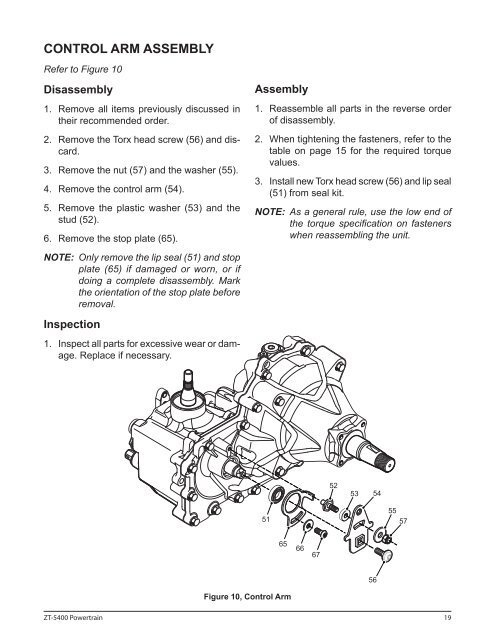
CONTROL ARM ASSEMBLY<br />
Refer to Figure 10<br />
Disassembly<br />
1. Remove all items previously discussed in<br />
their recommended order.<br />
2. Remove the Torx head screw (56) and discard.<br />
3. Remove the nut (57) and the washer (55).<br />
4. Remove the control arm (54).<br />
5. Remove the plastic washer (53) and the<br />
stud (52).<br />
6. Remove the stop plate (65).<br />
Assembly<br />
1. Reassemble all parts in the reverse order<br />
of disassembly.<br />
2. When tightening the fasteners, refer to the<br />
table on page 15 for the required torque<br />
values.<br />
3. Install new Torx head screw (56) and lip seal<br />
(51) from seal kit.<br />
NOTE: As a general rule, use the low end of<br />
the torque specification on fasteners<br />
when reassembling the unit.<br />
NOTE: Only remove the lip seal (51) and stop<br />
plate (65) if damaged or worn, or if<br />
doing a complete disassembly. Mark<br />
the orientation of the stop plate before<br />
removal.<br />
Inspection<br />
1. Inspect all parts for excessive wear or damage.<br />
Replace if necessary.<br />
51<br />
65<br />
66<br />
67<br />
52<br />
53 54<br />
55<br />
57<br />
56<br />
Figure 10, Control Arm<br />
<strong>ZT</strong>-<strong>5400</strong> Powertrain 19