
You also want an ePaper? Increase the reach of your titles
YUMPU automatically turns print PDFs into web optimized ePapers that Google loves.
Rudder and Elevator Servo Installation<br />
Required Parts<br />
Fuselage assembly Nylon clevis (2)<br />
Transmitter Receiver<br />
Receiver battery<br />
Servo with hardware (2)<br />
Silicone clevis retainer (2)<br />
Pushrod wire, 2-56 x 19 1 / 2 -inch (rudder)<br />
Pushrod wire, 2-56 x 18 3 / 4 -inch (elevator)<br />
Required Tools and Adhesives<br />
Pin vise<br />
Drill bit: 5/64-inch (2mm)<br />
Thin CA Phillips screwdriver: #1<br />
Side cutter Ruler<br />
<br />
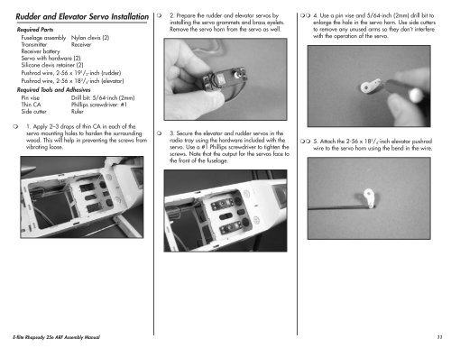
2. Prepare the rudder and elevator servos by<br />
installing the servo grommets and brass eyelets.<br />
Remove the servo horn from the servo as well.<br />
4. Use a pin vise and 5/64-inch (2mm) drill bit to<br />
enlarge the hole in the servo horn. Use side cutters<br />
to remove any unused arms so they don’t interfere<br />
with the operation of the servo.<br />
<br />
1. Apply 2–3 drops of thin CA in each of the<br />
servo mounting holes to harden the surrounding<br />
wood. This will help in preventing the screws from<br />
vibrating loose.<br />
<br />
3. Secure the elevator and rudder servos in the<br />
radio tray using the hardware included with the<br />
servo. Use a #1 Phillips screwdriver to tighten the<br />
screws. Note that the output for the servos face to<br />
the front of the fuselage.<br />
5. Attach the 2-56 x 18 3 / 4 -inch elevator pushrod<br />
wire to the servo horn using the bend in the wire.<br />
E-<strong>flite</strong> <strong>Rhapsody</strong> <strong>25e</strong> <strong>ARF</strong> Assembly Manual<br />
11