condair FF2
condair FF2
condair FF2
Create successful ePaper yourself
Turn your PDF publications into a flip-book with our unique Google optimized e-Paper software.
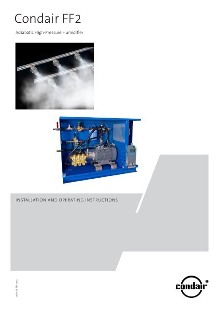
Condair <strong>FF2</strong><br />
Adiabatic High-Pressure Humidifier<br />
Installation and Operating Instructions<br />
2546058 EN 0902
Contents<br />
1 Introduction 4<br />
1.1 To the very beginning 4<br />
1.2 Notes on the installation and<br />
operating instructions 4<br />
2 For your safety 6<br />
3 Overview of Condair <strong>FF2</strong> 8<br />
3.1 Condair <strong>FF2</strong> system overview 8<br />
3.1.1 Stand-alone system<br />
(master configuration) 8<br />
3.1.2 Compound system<br />
(master-slave configuration) 9<br />
3.2 Pump station 10<br />
3.3 Humidifier unit 12<br />
3.4 Functional description 14<br />
3.5 Scope of delivery 17<br />
4 Notes on planning 18<br />
4.1 Record of site-specific data 18<br />
4.2 Accessories and options 19<br />
5 Installation works 20<br />
5.1 Important notes on installation 20<br />
5.2 Mounting of the nozzle unit 20<br />
5.2.1 Notes on positioning and<br />
mounting of the nozzle unit 20<br />
5.2.2 Mounting the nozzle unit 21<br />
5.3 Mounting the pump station 26<br />
5.3.1 Notes on positioning and<br />
mounting the pump station 26<br />
5.3.2 Dimension and weights of pump station 27<br />
5.3.3 Mounting the pump station 28<br />
5.3.4 Water installation 29<br />
5.4 Mounting the control unit <strong>FF2</strong> Slave 31<br />
5.5 Electrical installation 32<br />
5.5.1 Wiring diagram Master units<br />
(stand-alone units) 32<br />
5.5.2 Wiring diagram Slave units 33<br />
5.5.3 Notes on electric installation 34<br />
6 Initial commissioning 36<br />
6.1 Check list initial commissioning Condair <strong>FF2</strong> 36<br />
7 Operation 38<br />
7.1 Display and operating elements 38<br />
7.2 Setting the unit into operation 39<br />
7.3 Inspections during operation 40<br />
7.4 Setting the unit out of service 40<br />
8 Maintenance and replacement<br />
of components 41<br />
8.1 Important notes on maintenance 41<br />
8.2 Maintenance intervals 42<br />
8.3 Maintenance work 42<br />
8.4 Resetting the maintenance indication 43<br />
8.5 Removal of components 44<br />
8.5.1 Removal and installation of spray nozzles 44<br />
8.5.2 Replacement of piston packings 44<br />
8.6 Changing the oil of the piston pump 45<br />
9 Troubleshooting 46<br />
9.1 Important notes on troubleshooting 46<br />
9.2 Malfunction with error indication 46<br />
9.3 Resetting the error indication 46<br />
9.4 Malfunction without error indication 47<br />
9.5 Replacing the fuse of the control unit 49<br />
10 Product data 50<br />
10.1 Technical specifications/ambient conditions 50<br />
10.2 Declaration of conformity 51<br />
10 Appendix 52<br />
10.1 Diagram h,x 52<br />
11.2 Commissioaning protocol (copy template) 53
1 Introduction<br />
1.1 To the very beginning<br />
We thank you for having purchased the Condair <strong>FF2</strong> Adiabatic High Pressure Humidifier (“Condair<br />
<strong>FF2</strong>” for short).<br />
The Condair <strong>FF2</strong> incorporates the latest technical advances and meets all recognized safety<br />
standards. Nevertheless, improper use of the Condair <strong>FF2</strong> may result in danger to the user or third<br />
parties and/or impairment of material assets.<br />
To ensure a safe, proper, and economical operation of the steam humidifier Condair <strong>FF2</strong>, please<br />
observe and comply with all information and safety instructions contained in the present installation<br />
and operating instructions as well as the instructions given in the manuals for the components used<br />
in the humidification system.<br />
If you have questions, which are not or insufficiently answered in this documentation, please contact<br />
your Condair supplier. They will be glad to assist you.<br />
1.2 Notes on the installation and operating instructions<br />
Limitation<br />
The subject of these installation and operating instructions is Condair <strong>FF2</strong> Adiabatic High<br />
Pressure Humidifier. The various accessories are only described insofar as this is necessary for<br />
proper operation of the equipment. Further information on accessories can be obtained in the respective<br />
instructions.<br />
These installation and operating instructions are restricted to the installation, commissioning,<br />
operation, servicing and trouble shooting of the Condair <strong>FF2</strong> and is meant for well trained personnel<br />
being sufficiently qualified for their respective work.<br />
These installation and operating instructions are supplemented by various separate items of documentation<br />
(installation drawings, technical specifications, etc.). Where necessary, appropriate crossreferences<br />
are made to these publications in the installation and operating instructions.
Symbols used in this manual<br />
CAUTION!<br />
The catchword “CAUTION” designates notes in this installation and operating instructions that, if<br />
neglected, may cause damage and/or malfunction of the unit or other material assets.<br />
WARNING!<br />
The catchword “WARNING” used in conjunction with the general caution symbol designates safety<br />
and danger notes in this installation and operating instructions that, if neglected, may cause to<br />
injury to persons.<br />
DANGER!<br />
The catchword “DANGER” used in conjunction with the general caution symbol designates safety<br />
and danger notes in this installation and operating instructions that, if neglected, may lead to severe<br />
injury or even death of persons.<br />
Safekeeping<br />
Please safeguard these installation and operating instructions in a safe place, where they can be<br />
immediately accessed. If the equipment changes hands, the documentation must be passed on to<br />
the new operator.<br />
If the documentation gets mislaid, please contact your Condair supplier.<br />
Language versions<br />
These installation and operating instructions are available in various languages. Please contact your<br />
Condair supplier for information.<br />
Copyright protection<br />
The present installation and operating instructions is protected under the Copyright Act. Passing-on<br />
and reproduction of the manual (or part thereof) as well as exploitation and communication of the<br />
contents are prohibited without written permission by the manufacturer. Violation of copyright terms<br />
is subject to legal prosecution and arises liability for indemnification.<br />
The manufacturer reserves the right to fully exploit commercial patent rights.
2 For your safety<br />
General<br />
Every person working with the Condair <strong>FF2</strong> must have read and understood the installation and<br />
operating instructions before carrying out any work.<br />
Knowing and understanding the contents of the installation and operating instructions is a basic<br />
requirement for protecting the personnel against any kind of danger, to prevent faulty operation, and<br />
to operate the unit safely and correctly.<br />
All ideograms, signs and markings applied to the unit must be observed and kept in readable<br />
state.<br />
Qualification of personnel<br />
All actions described in the present installation and operating instructions (installation, operation,<br />
maintenance, etc.) must be carried out only by well trained and sufficiently qualified personnel<br />
authorised by the owner.<br />
For safety and warranty reasons any action beyond the scope of this manuals must be carried out<br />
only by qualified personnel authorised by the manufacturer.<br />
It is assumed that all persons working with the Condair <strong>FF2</strong> are familiar and comply with the appropriate<br />
regulations on work safety and the prevention of accidents.<br />
Intended use<br />
The Condair <strong>FF2</strong> is intended exclusively for humidification in ventilation systems within the specified<br />
operating conditions (see chapter 10 “Product specifications”). Any other type of application<br />
without the express written consent of the manufacturer is considered as not conforming with the<br />
intended purpose and may lead to the Condair <strong>FF2</strong> becoming dangerous.<br />
Operation of the equipment in the intended manner requires that all the information in these installation<br />
and operating instructions is observed (in particular the safety instructions)
Danger that may arise from the unit<br />
CAUTION!<br />
Danger of electric shock<br />
One may get in touch with live parts when the pump station/ control unit is open. Touching<br />
live parts may cause severe injury or danger to life..<br />
Prevention: before carrying out any work on the Condair <strong>FF2</strong>, set the unit out of operation as described<br />
in chapter 7.4 (switch off the unit, disconnect it from the mains and stop the water supply)<br />
and secure the unit against inadvertent power-up.<br />
WARNING!<br />
Poorly maintained humidification systems may endanger health. When insufficiently maintained<br />
harmful germs can build up in the air duct and affect the duct air.<br />
Prevention: as described in chapter 8 “Maintenance”, the Condair <strong>FF2</strong> must be cleaned in the<br />
specified intervals and the cleaning work must be carried out correctly.<br />
WARNING!<br />
During operation the water system is at high pressure. Inappropriately fastened hoses can be<br />
torn out of the screw connections during operation by the high pressure. There is danger of injury,<br />
in no circumstances loosen any hoses or screw connections during operation.<br />
Prevention: always correctly tighten the high pressure hoses and screw connections and do not<br />
loosen any hoses or screw connections during operation. Before carrying out any work on the Condair<br />
<strong>FF2</strong>, set the unit out of operation as described in chapter 7.4 (switch off the unit, disconnect it<br />
from the mains and stop the water supply) and secure the unit against inadvertent power-up.<br />
Behaviour in case of danger<br />
If it is suspected that safe operation is no longer possible, then the Condair <strong>FF2</strong> should immediately<br />
be shut down and secured against accidental power-up according to chapter 7.4 (switch off systems,<br />
disconnect it from the mains and stop the water supply). This can be the case under the following<br />
circumstances:<br />
– if components of the Condair <strong>FF2</strong> are damaged, worn or badly soiled.<br />
– if the Condair <strong>FF2</strong> does not work correctly.<br />
– if connectors and lines are leaking.<br />
– after longtime storage under unfavourable conditions.<br />
– after transportation under unfavourable conditions.<br />
All persons working with the Condair <strong>FF2</strong> must report any alterations to the unit that may affect safety<br />
to the owner without delay.<br />
Prohibited modifications to the unit<br />
No modifications must be undertaken on the Condair <strong>FF2</strong> without the express written consent of<br />
the manufacturer.<br />
For the replacement of defective components use exclusively original accessories and spare parts<br />
available from your Condair supplier.
3 Overview of Condair <strong>FF2</strong><br />
3.1 Condair <strong>FF2</strong> system overview<br />
3.1.1 Stand-alone system (master configuration)<br />
Humidifier unit consisting of:<br />
1 Step valves Y3, Y4 and Y5<br />
2 Nozzle unit<br />
3 Droplet separator (option or product of other manufacturer)<br />
4 Flushing valve high pressure system (option)<br />
2<br />
3<br />
1<br />
7<br />
4<br />
6<br />
5<br />
8<br />
Pump station consisting of:<br />
5 Pump unit<br />
6 Control unit<br />
7 High-pressure piping<br />
8 Floor stand (option)
3.1.2 Compound system (master-slave configuration)<br />
Assuming the maximum pump capacity is sufficient, the pump station of a stand-alone system may<br />
supply pressurized water to up to three further <strong>FF2</strong> systems building a so-called master-slave configuration<br />
as shown below.<br />
Slave system 3<br />
Slave system 2<br />
Slave systems consisting of:<br />
– control unit <strong>FF2</strong> slave<br />
– humidifier unit<br />
Slave system 1<br />
Bus cable<br />
High-pressure piping<br />
Master system consisting of:<br />
– pump station<br />
– humidifier unit
10<br />
3.2 Pump station<br />
Overview<br />
15<br />
14<br />
13<br />
12<br />
11<br />
10<br />
9<br />
8<br />
7<br />
6<br />
5<br />
4<br />
3<br />
2<br />
16<br />
17<br />
18<br />
19<br />
20<br />
21<br />
22<br />
23<br />
24<br />
25<br />
1<br />
26<br />
1 Oil pan<br />
2 Connector housing drain<br />
3 Jetting pump<br />
4 Pump motor<br />
5 Flush/relief connector<br />
6 High-pressure connector<br />
7 Supply connector<br />
8 Stop valve<br />
9 Pressure transmitter (working pressure)<br />
10 Supply valve<br />
11 Pressure reducing valve<br />
12 Water filter<br />
13 Flushing valve (supply)<br />
14 Conductivity sensor (option)<br />
15 Safety valve supply pressure<br />
16 Safety valve working pressure<br />
17 Manometer working pressure<br />
18 Manometer supply pressure<br />
19 Minimum pressure switch (supply pressure)<br />
20 Frequency converter pump motor<br />
21 Driver board<br />
22 Rating plate<br />
23 BMS gateway (option e-LINKS <strong>FF2</strong>)<br />
24 Remote operation/fault indication board (option)<br />
25 Display and control unit with control<br />
26 Floor stand (option)
11<br />
Brief description of pump station<br />
The pump station consists of the control unit and the pump unit and it is supplied in a housing ready<br />
for connection.<br />
Pump unit: The oil-lubricated high pressure pump is directly mounted to the electric motor and reaches<br />
the maximum capacity of 1’080 kg/h at an operating pressure of 80 bar. Assuming the maximum<br />
pump capacity is sufficient, up to three further <strong>FF2</strong> systems may be connected to the jetting pump<br />
via the high-pressure circular piping.<br />
A minimum pressure switch continuously monitors the minimum supply pressure and a pressure<br />
transmitter continuously monitors the minimum working pressure. They stop pump operation in case<br />
the minimum pressure values drop below the limit for a certain time. Two safety valves ensure that<br />
the maximum supply pressure and the maximum working pressure are not exceeded. The pressure<br />
reducing valve maintains constant supply pressure.<br />
Supply valve<br />
Water filter<br />
Min. pressure switch<br />
supply pressure<br />
High pressure<br />
pump<br />
Pressure transmitter<br />
working pressure<br />
Stop valve<br />
Pressure<br />
reducing valve<br />
Conductivity sensor<br />
(option)<br />
Manometer<br />
supply pressure<br />
Manometer<br />
working pressure<br />
High pressure piping<br />
M<br />
Step valves<br />
Safety valve<br />
supply pressure<br />
Safety valve<br />
working pressure<br />
Y6<br />
Safety valve supply “Y2”<br />
Relief valve<br />
working<br />
pressure<br />
(option)<br />
Step valves<br />
Slave 1 ... Slave 3<br />
At the installation site, the supply line of demineralized water, the high-pressure hose of the piping<br />
(accessory) and the drain must be connected to the jetting pump.<br />
Control unit: the control unit consists of the display and control unit, the driver board, the frequency<br />
converter for the control of the high pressure pump and the connection terminals for the power supply<br />
(380...400V/3N~/50-60Hz). Optionally the control unit can be equipped with a remote operating and<br />
fault indication print, a conductivity monitoring and a BMS gateway (e-LINKS <strong>FF2</strong>) for the integration<br />
into a building management system (BMS).<br />
The pump station is electrically wired at the factory. At the installation site, the power supply, the<br />
humidity controller or humidity sensor, the remote operating and fault indication (option), the external<br />
safety chain and the step valves must be electrically connected to the control unit.
12<br />
3.3 Humidifier unit<br />
1<br />
2<br />
3<br />
4<br />
5<br />
6<br />
7<br />
8<br />
9<br />
10<br />
11<br />
13<br />
10<br />
11<br />
12<br />
1 Supporting structure nozzle unit<br />
2 Nozzle pipes<br />
3 Spray nozzle<br />
4 High-pressure piping from pump station<br />
5 Step valve Y3 (1/7)<br />
6 Step valve Y4 (2/7)<br />
7 Step valve Y5 (4/7)<br />
8 Flushing valve Y6 working pressure (option)<br />
9 Water drain after nozzles<br />
10 Siphon (by customers,<br />
height adapted to duct pressure)<br />
11 Open drain funnel (by customers)<br />
12 Droplet separator (option or product of<br />
other manufacturer)<br />
13 Water drain after humidifier unit
13<br />
Nozzle unit<br />
The nozzle unit consists of several nozzle pipes, which are equipped with the necessary number of<br />
nozzles (system-specific). The individual nozzle pipes are divided into three different spray circuits<br />
(1/7, 2/7 and 4/7). The spray circuits are connected via a high pressure hoses to the corresponding<br />
step valves (either directly or via a distribution blocks).<br />
Droplet separator<br />
The installation of a droplet separator is the customers responsibility. An optional droplet separator is<br />
available for the Condair <strong>FF2</strong> (see opposite illustration). Detailed information regarding the optional<br />
droplet separator can be found in the separate documentation to this product.
14<br />
3.4 Functional description<br />
5<br />
380...400V/3N~/50-60Hz<br />
8<br />
9<br />
4<br />
10<br />
Current<br />
Water<br />
1<br />
11<br />
13<br />
3b<br />
PID<br />
12<br />
2<br />
14<br />
Elementary diagram of Condair <strong>FF2</strong> (stand-alone system)<br />
P/PI<br />
26 27 28<br />
25<br />
3a<br />
24<br />
23<br />
Y3<br />
(1/7)<br />
Y4<br />
(2/7)<br />
Y5<br />
(4/7)<br />
22<br />
21<br />
Y6<br />
20<br />
19<br />
6<br />
M<br />
15<br />
16<br />
7<br />
Y2<br />
17<br />
18<br />
1 Pump station<br />
2 Control unit<br />
3a External P- or PI-controller<br />
3b Internal PID controller<br />
4 Remote operation/fault indication relay<br />
5 Power supply<br />
6 Frequency converter pump motor<br />
7 Jetting pump<br />
8 Stop valve<br />
9 Supply valve<br />
10 Pressure reducing valve<br />
11 Water filter<br />
12 Conductivity sensor<br />
13 Safety valve (supply pressure)<br />
14 Min. pressure switch (supply pressure)<br />
15 Pressure transmitter (working pressure)<br />
16 Flushing valve Y2 supply pressure<br />
17 Safety valve (working pressure)<br />
18 Drain pump station (by customers)<br />
19 High-pressure piping<br />
20 Flushing valve Y6 working pressure (option)<br />
21 Step valves Y3, Y4 and Y5<br />
22 Duct drains with siphon (by customers)<br />
23 Droplet separator<br />
24 Spray nozzles<br />
25 Air filter min. F7 (by customers)<br />
26 Humidity sensor (by customers)<br />
27 Safety humidistat<br />
(safety chain, by customers)<br />
28 Flow monitoring device<br />
(safety chain, by customers)
15<br />
5<br />
380...400V/3N~/50-60Hz<br />
8<br />
Master<br />
4<br />
9<br />
10<br />
Current<br />
Water<br />
Bus<br />
1<br />
11<br />
13<br />
3b<br />
PID<br />
12<br />
14<br />
Elementary diagram of Condair <strong>FF2</strong> (master-slave compound configuration)<br />
P/PI<br />
25<br />
3a<br />
P/PI<br />
26 27 28<br />
26 27 28<br />
25<br />
3a<br />
24<br />
23<br />
24<br />
23<br />
Y3<br />
(1/7)<br />
Y4<br />
(2/7)<br />
Y5<br />
(4/7)<br />
22<br />
Y3<br />
(1/7)<br />
Y4<br />
(2/7)<br />
Y5<br />
(4/7) 22<br />
21<br />
21<br />
Slave 2 ... Slave 3<br />
Slave 1<br />
Y6 20<br />
3b<br />
Y6 20<br />
4<br />
2<br />
PID<br />
2<br />
19<br />
5<br />
Slave 2 ... Slave 3<br />
29<br />
6<br />
230V/1N~/50-60Hz<br />
7<br />
M<br />
15<br />
16<br />
Y2<br />
18<br />
17<br />
1 Pump station<br />
2 Control unit<br />
3a External P- or PI-controller<br />
3b Internal PID controller<br />
4 Remote operation/fault indication relay<br />
5 Power supply<br />
6 Frequency converter pump motor<br />
7 Jetting pump<br />
8 Stop valve<br />
9 Supply valve<br />
10 Pressure reducing valve<br />
11 Water filter<br />
12 Conductivity sensor<br />
13 Safety valve (supply pressure)<br />
14 Min. pressure switch (supply pressure)<br />
15 Pressure transmitter (working pressure)<br />
16 Flushing valve Y2 supply pressure<br />
17 Safety valve (working pressure)<br />
18 Drain pump station (by customers)<br />
19 High-pressure piping<br />
20 Flushing valve Y6 working pressure<br />
(option)<br />
21 Step valves Y3, Y4 and Y5<br />
22 Duct drains with siphon (by customers)<br />
23 Droplet separator<br />
24 Spray nozzles<br />
25 Air filter min. F7 (by customers)<br />
26 Humidity sensor (by customers)<br />
27 Safety humidistat<br />
(safety chain, by customers)<br />
28 Flow monitoring device<br />
(safety chain, by customers)<br />
29 RJ45 bus cable
16<br />
General<br />
Via the stop valve (8) the fully demineralized water (also called permeate) is fed from the reversing<br />
osmosis system (RO system) to the pump station (1).<br />
If the control unit is operational and a humidification request is present, the supply valve (9) and<br />
the flushing valve (16) open simultaneously and the pump circuit is flushed. After a certain time the<br />
flushing valve (16) closes again. If the supply pressure is within the admissible range the jetting pump<br />
(7) starts and builds up the required working pressure. The jetting pump feeds the water to the step<br />
valves (21) via the high-pressure piping (19). One, two or all three step valves open, depending on<br />
the humidification required (see step diagram below).<br />
The demineralized water then flows to the respective spray nozzles (24) where it is atomized into a<br />
fine aerosol mist and absorbed by the air passing by.<br />
A droplet separator (23) (option or product of other manufacturer) downstream make sure no aerosols<br />
are carried over to the air passing by. Waste water flows down from the droplet separators to the<br />
duct drains (22) and the siphons.<br />
If there is no humidification request the pump automatically stops after a short time.<br />
Control<br />
With stand-alone systems (master configuration) the control unit is built into the pump station. The<br />
control unit features a separate power supply (380...400V/3N~/50-60Hz), a control/humidity signal<br />
input, connectors for the external safety chain and relay connectors for the remote operation and<br />
fault indication (option). In addition, the control unit incorporates the frequency converter for the<br />
control of the jetting pump.<br />
With compound systems, each slave is equipped with a separate control unit. Each control unit<br />
features a separate power supply (230V/1N~/50-60Hz), a control/humidity signal input, connectors<br />
for the external safety chain and relay connectors for the remote operation and fault indication (option).<br />
A bus cable (29) connects each slave control unit to the control unit of the master system that<br />
controls the jetting pump.<br />
Humidification<br />
The control of the humidification system is established via an external P/PI controller (3a) or the PID<br />
controller built into the control unit (3b).<br />
As standard the humidification is effected with 7-stages in accordance with the following diagram.<br />
Finer gradations are possible. Contact your Condair supplier if necessary.<br />
Step 1 to 7<br />
0 1/7<br />
2/7<br />
3/7<br />
4/7<br />
5/7<br />
6/7<br />
7/7<br />
Step valve Y3 (1/7)<br />
Step valve Y4 (2/7)<br />
Step valve Y5 (4/7)<br />
0<br />
0<br />
0<br />
1<br />
0<br />
0<br />
0<br />
1<br />
0<br />
1<br />
1<br />
0<br />
0<br />
0<br />
1<br />
1<br />
0<br />
1<br />
0<br />
1<br />
1<br />
1<br />
1<br />
1<br />
100<br />
Capacity [%]<br />
0<br />
0 100<br />
Demand [%]
17<br />
Monitoring of jetting pump<br />
The minimum supply and working pressure values are permanently monitored. The jetting pump<br />
automatically stops if one of these values is outside the admissible range. A respective error message<br />
appears in the display, the red lamp “Error” lights up.<br />
In addition to the electronic monitoring the jetting pump is equipped with two mechanical safety<br />
valves for the supply and working pressure. These valves open if the admissible supply pressure or<br />
working pressure are exceeded.<br />
In addition, the control unit of the pump station and the salve control units can be equipped with a<br />
remote operating and fault indication print. Thus the following operating conditions can be displayed<br />
over the appropriate relays: “Error”, “Humidification”, “Maintenance” and “Unit on”.<br />
3.5 Scope of delivery<br />
The delivery includes:<br />
– Pump station complete with control unit and built-in PID controller and optional items as ordered<br />
according chapter 4.3.<br />
– Nozzle unit including mounting accessories<br />
– High-pressure hoses (2 m, 5 m or 10 m) for high-pressure piping<br />
– 3 m anti-chafe spiral hose<br />
– RJ45 Bus cable (20 m or 10 m, other lengths available on request), for compound systems<br />
only<br />
– Special cable to step valves Y3, Y4 and Y5<br />
– Installation and operating instructions (the document you are currently reading)<br />
– Installation drawing with mounting dimensions<br />
– Tubing diagram
18<br />
4 Notes on planning<br />
Prior to designing and selecting a Condair <strong>FF2</strong> humidification system the following preparatory steps<br />
must be carried out:<br />
• Collecting site-specific data required for system design (see chapter 4.1)<br />
• Selecting the desired options (see chapter 4.2)<br />
4.1 Record of site-specific data<br />
Your Condair representative needs the following data for proper system design:<br />
Duct dimensions<br />
Width (inner) mm _________<br />
Height (inner) mm _________<br />
Length (inner, min. 1300 mm) mm _________<br />
Wall thickness of duct in the area of the water tubing pass-through mm _________<br />
Air velocity in duct, or m/s _________<br />
air volume to be humidified per hour m3/h _________<br />
Air pressure (absolute) in housing --> not mandatory necessarily Pa _________<br />
State of supply air prior to humidification<br />
Temperature T1 °C _________<br />
Humidity x1 g/kg / %rh _________<br />
Desired state of air after humidification<br />
Temperature T2 °C _________<br />
Humidity x2 g/kg / %rh _________<br />
Important notes:<br />
– If a particular site is to be equipped with several <strong>FF2</strong> systems determine the above data for each<br />
system separately. Your Condair representative will then evaluate whether the particular systems<br />
may be operated in a master-slave compound configuration.<br />
– Evaporating aerosols cools down the air inside the duct (adiabatic cooling effect). To achieve the<br />
desired air temperature the supply air must be heated prior to humidification.
19<br />
4.2 Accessories and options<br />
Accessories<br />
Accessory<br />
High-pressure hose for<br />
high-pressure piping<br />
Anti-chafe spiral hose<br />
RJ45 bus cable<br />
Description<br />
High-pressure hoses for establishing the high-pressure<br />
piping between the high-pressure connectors of the<br />
pump.<br />
Hoses of 2 m, 5 m or 10 m length available (from stock)<br />
The anti-chafe spiral hose protects the high-pressure<br />
hoses in locations where they are subject to get in touch<br />
with each other or with other system components.<br />
Length: 3 m<br />
The bus cable connects the control units of a masterslave<br />
configuration.<br />
Length: 10 m or 20 m<br />
Options<br />
Option<br />
Floor stand for pump station<br />
Droplet separator<br />
Remote operating and fault<br />
indication<br />
Conductivity monitoring<br />
Flushing valve Y6<br />
e-LINKS <strong>FF2</strong><br />
Floor stand for pump station<br />
Floor stand made of corrosion resistant steel, for mounting<br />
the pump station at a convenient height for easy operation.<br />
Droplet separator in frame construction made of corrosion<br />
resistant steel equipped with collector meshes with<br />
a special biocide coating.<br />
With unfavourable flow conditions and/or high air speed<br />
in the duct additionally a deflection sheet is provided for<br />
the optimization of the incident air flow of the first droplet<br />
separator.<br />
Print with relay contacts for the remote indication of the<br />
following operating conditions: Unit on, Humidification,<br />
Error and Maintenance.<br />
The conductivity monitoring, consisting of the conductivity<br />
sensor and the conductivity print, monitors the<br />
electrical conductivity of the water and outputs an error<br />
message if the lower limit value is exceeded.<br />
Flushing valve for the automatic flushing of the high<br />
pressure piping during operation. The flushing valve is<br />
installed directly to the step valve block.<br />
Gateway to connect the Condair <strong>FF2</strong> to a building management<br />
system. Two versions are available:<br />
BACnet/IP or LonWorks
20<br />
5 Installation works<br />
5.1 Important notes on installation<br />
Qualification of personnel<br />
All installation work must be performed only by persons familiar with the Condair <strong>FF2</strong> Adiabatic<br />
High Pressure Humidifier and sufficiently qualified for such work.<br />
All work concerning the electric installation must be performed only by adequately qualified<br />
personnel (electrician or workman with equivalent training).<br />
Safety<br />
For all installation work the ventilation system in which the Condair <strong>FF2</strong> will be installed is to be<br />
rendered inoperative and prevented from further inadvertent operation.<br />
The pump station and possible Slave control units may be connected to electric mains only after all<br />
installation work has been completed.<br />
General notes<br />
All statements relating to the correct positioning and installation of the particular components<br />
of the Condair <strong>FF2</strong> (see chapter 5.2 and 5.3) must be followed and complied with.<br />
When installing components of the Condair <strong>FF2</strong> use the fixing materials supplied with the unit.<br />
If fixing with the materials supplied is not possible in your particular case, select a method of fixing<br />
that is of similar stability. In case of doubt, please contact your Condair supplier.<br />
5.2 Mounting of the nozzle unit<br />
5.2.1 Notes on positioning and mounting of the nozzle unit<br />
The system-specific dimensions for the positioning of the nozzle unit in the duct are to be found in<br />
the installation documents, which are provided with your system.<br />
In addition to the installation instructions please observe the following complementary notes on<br />
mounting:<br />
– Caution, fully demineralized water is aggressive! The Condair <strong>FF2</strong> system uses fully demineralized<br />
water. All components (duct/monoblock, mounting accessories, drain line, etc.) in the<br />
humidifier unit area must be made of stainless steel (DIN 1.4301/AISI 304 or better) or plastic<br />
resistant to fully demineralized water.<br />
– For the installation and maintenance of the humidifier unit the ventilation duct/monoblock must<br />
be equipped with a viewing window and a sufficiently large maintenance access door.<br />
– In the humidifier unit area the ventilation duct/monoblock must be waterproof.<br />
– If the ambient air is cold the ventilation duct must be isolated to prevent the humidified air from<br />
condensating at the walls.<br />
– Important! At the site of installation an air filter meeting the F7 quality specifications or<br />
better must be installed before the humidifier unit.
21<br />
– The section of the duct holding the humidifier unit must be equipped with a tub having<br />
two water drains, one before and one after the droplet separators. Make sure the water<br />
in the tub has unhampered access to the drains. Each water drain must be connected to<br />
the sewage system separately, via a siphon. For hygienic reasons these should be open<br />
drains to the sewage line of the site.<br />
Important: The effective height of the siphon depends on the duct pressure. The proper<br />
layout of the draining system is the customer’s duty.<br />
– The minimum distance of 0,4 m between the humidifier unit and a possible heating unit as<br />
well as the mounting dimensions according to the system diagram must be complied with.<br />
– To prevent water drops from breaking away at the droplet separators the air flow to the humidifier<br />
unit must be uniform with regard to the entire diameter. Air rectifiers or perforated plates<br />
must be installed before the humidifier unit, as required.<br />
– The admissible air velocity in the duct before the humidifier unit is 0.5 ... 4.0 m/s.<br />
– If silencers are installed in the air conditioning unit, make sure they are installed with a minimum<br />
distance of 3 m before or after the Condair <strong>FF2</strong>.<br />
5.2.2 Mounting the nozzle unit<br />
1. Installing the vertical mounting rails: mark the position of the fixing straps at the duct wall,<br />
then drill the ø3.3 mm fixing holes.<br />
Important! Make sure that the fixing holes in the left and right duct wall are exactly aligned<br />
opposite each other and that the axes of the upper and lower fixing holes are at right angles<br />
to the ceiling of the duct.<br />
Then, fix the vertical mounting rails to the wall of the duct with the fixing straps and the self-tapping<br />
screws provided.
22<br />
2. Mounting the pipe supports: Fix the pipe supports to the vertical mounting rails using the screws<br />
and sliding nuts provided (vertical position according to the installation drawing).<br />
Important! Align opposite pipe supports exactly horizontal.<br />
3. Mounting the nozzle pipes: Fix nozzle pipes to the pipe supports using the fixing straps, screws<br />
and washers provided (positioning of the nozzle pipes according to the installation drawing).<br />
Before tightening the fixing straps, make sure the outlet openings of the nozzles are aligned<br />
exactly horizontal in flow direction.
23<br />
4. Mounting the central support rail (only for ducts with a width a >2 m): Fix central support<br />
rail to the nozzle pipes using the fixing straps, screws, washers and sliding nuts provided. Fix<br />
lower and upper angle bracket to the central support rail using the screws, washers and sliding<br />
nuts provided. Finally fix the angle brackets to the duct ceiling and the duct bottom using the<br />
self-tapping screws provided (first drill the ø3.3 mm holes).<br />
5. Mounting the distribution blocks (systems with more than three nozzle pipes only): Fix<br />
distribution blocks to the vertical mounting rails using the screws and washers provided (positioning<br />
according to the installation drawing).
24<br />
6. Mounting the step valve block: Fix the step valve block at the appropriate position to the duct<br />
using the self-tapping screws provided.<br />
Then, drill duct passages ø32.5 mm and close the holes inside and outside with the rubber<br />
sleeves provided.<br />
7. Connecting the high-pressure hoses to the step valve block: Connect the high-pressure<br />
hoses to the step valve block, then lead the hoses through the rubber sleeves into the duct as<br />
shown in the illustration below.
25<br />
8. Connecting the high-pressure hoses to the spray circuits: Connect the high-pressure hoses<br />
to the appropriate distribution blocks and nozzle pipes (position of the spray circuits according<br />
to the installation drawing). Make sure the hoses are not kinked (if necessary, lead hoses in a<br />
bow to the connector).<br />
1/7 2/7<br />
4/7
26<br />
5.3 Mounting the pump station<br />
5.3.1 Notes on positioning and mounting the pump station<br />
Please observe the following notes on positioning and mounting:<br />
– Place the pump station in a way that:<br />
– the distance to the humidifier unit is as short as possible.<br />
Note: High-pressure hoses of 2 m, 5 m or 10 m length are available from stock.<br />
– it is freely accessible and there is enough space for convenient operation and maintenance<br />
(min. free space around pump station: laterally 0.5 m, in front 0.6 m).<br />
– The pump station is designed for the operation in protected rooms and must therefore not be<br />
installed outside.<br />
– Do not install the pump station in exposed locations or locations with heavy dust load.<br />
– The pump station must be installed only in a location having a water drain on the floor. If this<br />
is not possible, it is mandatory to provide water sensors to safely interrupt water supply in case<br />
of leakage. Furthermore, choose a suitable location that prevents damage to material assets in<br />
case of leakage.<br />
– The pump station is designed for installation on a load-carrying floor or on the optional floor<br />
stand. The pump station or the floor stand must be fixed with screws to the floor (protection<br />
against shifting and tilting).<br />
Caution! Do not install the pump station to vibrating components.
27<br />
5.3.2 Dimension and weights of pump station<br />
all dimensions in mm<br />
904<br />
25<br />
83<br />
404<br />
770<br />
376<br />
248<br />
538<br />
602<br />
662<br />
855<br />
181,5<br />
347,5<br />
38<br />
895<br />
min. 500<br />
min. 500<br />
min. 800<br />
Weight of pump station:<br />
Weight of floor stand:<br />
approx. 80 kg<br />
approx. 6 kg
28<br />
5.3.3 Mounting the pump station<br />
Mount the pump station at the desired location in accordance with the following figure directly to the<br />
floor (left figure) or mount the unit on the optional floor stand (right figure).<br />
855<br />
347,5<br />
120<br />
327.5<br />
347,5<br />
327.5<br />
120<br />
120<br />
327.5<br />
347,5<br />
327.5<br />
120
29<br />
5.3.4 Water installation<br />
Master Slave 1...3<br />
Y6 **<br />
Y3 Y4 Y5<br />
Y3 Y4 Y5<br />
M20x1.5<br />
ø19 mm hose connector<br />
or G 1/2" inside thread<br />
Notes on water installation<br />
– Use hoses to connect the supply flushing line and the tub drain to an open drain funnel (make<br />
sure to install the hoses correctly).<br />
– The working pressure flushing valve Y6 (**) is mounted directly to the step valve block of the<br />
Master unit (stand-alone system) or the last Slave unit (Compound systems). The drain hose<br />
of the flushing valve is to be connected to an open drain funnel (make sure to install the hose<br />
correctly).<br />
– Use only the optional high-pressure hoses to establish the high-pressure piping between the<br />
high-pressure connection of the pump station and the step valve block (or between step valve<br />
blocks of the Slave units, respectively). Other hoses may get damaged in operation and cause<br />
system breakdown.
30<br />
– Important! Before connecting, all water hoses must be flushed with fully demineralized<br />
water for at least 10 minutes. Remove the sealing caps from the connectors just shortly before<br />
installing the hoses.<br />
– Install the high-pressure hoses in a way that they do not get in touch with each other or other<br />
system components. Where this is not possible for any reason protect the high-pressure hoses<br />
using the supplied anti-chafe spiral hose. In the locations exposed to chafing wrap the anti-chafe<br />
spiral hose helically around the high-pressure hoses(s).
31<br />
5.4 Mounting the control unit <strong>FF2</strong> Slave<br />
CAUTION!<br />
The electronic components inside the control unit are very sensitive to electrostatic discharge.<br />
When the unit is open for installation work, appropriate measures must be taken to protect these<br />
components against damage caused by electrostatic discharge (ESD protection).<br />
2.<br />
236 mm<br />
220 mm<br />
3.<br />
306 mm<br />
280 mm<br />
1.<br />
Detail “B”<br />
Detail “A”<br />
1. Unlock and swivel up the transparent cover, then unlock the two hinges (see detail “A”) and<br />
remove the cover.<br />
2. Undo the 6 screws, then carefully lift the control unit cover and disconnect the cables on the<br />
electronic.<br />
3. Break out the 4 oblong holes in the bottom of the unit housing and fix the control unit to the wall<br />
using 4 screws.<br />
4. Connect the voltage supply, the control signal, etc. to the corresponding terminals in the control<br />
unit according the appropriate wiring diagram (see chapter 5.5.2).<br />
Important: all cables must be lead into the control unit via the cable glands.
32<br />
5.5 Electrical installation<br />
5.5.1 Wiring diagram Master units (stand-alone units)<br />
B2<br />
B1<br />
X1<br />
Y<br />
- +<br />
X2<br />
X8<br />
B3<br />
X3<br />
B5<br />
M<br />
3~<br />
φ<br />
B6<br />
GND<br />
Press<br />
F5<br />
P<br />
N<br />
P1<br />
X11<br />
GND<br />
Input+<br />
Input+<br />
200mAF<br />
S1<br />
F4<br />
X10<br />
1<br />
GND<br />
Out FC+<br />
24V<br />
5V<br />
L1 N L1 N<br />
4<br />
2 5<br />
Front Panel<br />
+24V<br />
Res1<br />
Res2<br />
Lev/Tp<br />
P min.<br />
+24V<br />
X9<br />
F1<br />
6.3AT<br />
L1<br />
N<br />
SC1<br />
SC2<br />
PT1<br />
PT2<br />
B7<br />
J<br />
Option<br />
Conductivity<br />
RS485 Master<br />
Slave System<br />
K1<br />
X<br />
B4<br />
X<br />
F3<br />
630mAT<br />
F2<br />
1AT<br />
Enable<br />
FC<br />
N<br />
N<br />
UV/Fan<br />
Drain Valve<br />
Inlet Valve<br />
JP3<br />
N<br />
Stage 3<br />
Stage 2<br />
Stage 1<br />
N<br />
Pump<br />
N<br />
HighP<br />
H<br />
Error<br />
X4<br />
X5<br />
Y1<br />
5 Y5<br />
3<br />
1<br />
X6<br />
Y6<br />
X7<br />
Service<br />
Steam<br />
Unit On<br />
V<br />
Y2<br />
Y4<br />
Y3<br />
K<br />
U V W B7 T1T2<br />
GND +<br />
B4 Drive Enable<br />
B2 +24V<br />
B5 Run forward<br />
T5<br />
T6<br />
Q<br />
F6<br />
L1 L2 L3<br />
L1 L2 L3 N<br />
3 x 400V<br />
L1 L2 L3 N PE<br />
U<br />
B1 Pressure transmitter 1...10V<br />
B2 Active humidity controller or humidity sensor<br />
B3 Minimum pressure switch (supply pressure)<br />
B4 Conductivity monitoring print (option)<br />
B5 Conductivity sensor (option)<br />
B6 Temperature sensor motor coil<br />
B7 Ventilator interlock<br />
F1 Fuse 6.3A, slow-acting (power supply control unit)<br />
F2 Fuse 1A, slow-acting (Relay 230V)<br />
F3 Fuse 630mA, quick-acting (step valves)<br />
F4 Fuse 200mA, quick-acting (analogue entry)<br />
F5 Fuse 200mA, quick-acting (24 VDC supply)<br />
F6 External fuse 10A, slow-acting (voltage supply 3x400V)<br />
H Remote operating and fault indication (option)<br />
J Cable bridge (must be removed, if B7 is connected)<br />
JP3 Jumper must be set, if Slave unit is connected<br />
K Main contactor<br />
K1 External safety chain (safety humidistat, flow control,<br />
ventilator interlock, etc.)<br />
M Motor high-pressure pump<br />
Q External service switch (min. contact clearance 3<br />
mm) or plug-type connector (installation mandatory)<br />
S1 Unit switch<br />
U Frequency converter pump motor<br />
V Ventilator pump motor<br />
X Bus connection Master-Slave systems<br />
Y1 Supply valve<br />
Y2 Flushing valve supply pressure<br />
Y3 Step valve 1/7<br />
Y4 Step valve 2/7<br />
Y5 Step valve 4/7<br />
Y6 Flushing valve working pressure (option)
33<br />
5.5.2 Wiring diagram Slave units<br />
B2<br />
Y<br />
- +<br />
X1<br />
X2<br />
X8<br />
GND<br />
Press<br />
F5<br />
GND<br />
Input+<br />
Input+<br />
F4<br />
GND<br />
Out FC+<br />
+24V<br />
Res1<br />
Res2<br />
Lev/Tp<br />
P min.<br />
+24V<br />
Enable<br />
FC<br />
200mAF<br />
24V<br />
5V<br />
RS485 Master<br />
Slave System<br />
N<br />
N<br />
UV/Fan<br />
Drain Valve<br />
Inlet Valve<br />
P<br />
N<br />
P1<br />
X11<br />
L1 N L1 N<br />
X10<br />
1 4<br />
X9<br />
F1<br />
6.3AT<br />
L1<br />
N<br />
SC1<br />
SC2<br />
PT1<br />
PT2<br />
J<br />
K1<br />
X<br />
F3<br />
630mAT<br />
F2<br />
1AT<br />
JP3<br />
N<br />
Stage 3<br />
Stage 2<br />
Stage 1<br />
N<br />
Pump<br />
N<br />
HighP<br />
5 Y5<br />
3<br />
1<br />
X6<br />
Y6<br />
X7<br />
Y4<br />
Y3<br />
S1<br />
2 5<br />
Q<br />
B7<br />
from Master<br />
Error<br />
Service<br />
Steam<br />
Unit On<br />
F6<br />
H<br />
L1 N PE<br />
230 V<br />
X<br />
to next Slave<br />
B2 Active humidity controller or humidity sensor<br />
B7 Ventilator interlock<br />
F1 Fuse 6.3A, slow-acting (power supply control unit)<br />
F2 Fuse 1A, slow-acting (Relay 230V)<br />
F3 Fuse 630mA, quick-acting (step valves)<br />
F4 Fuse 200mA, quick-acting (analogue entry)<br />
F5 Fuse 200mA, quick-acting (24 VDC supply)<br />
F6 External fuse 10A, slow-acting (voltage supply 3x400V)<br />
H Remote operating and fault indication (option)<br />
J Cable bridge (must be removed, if B7 is connected)<br />
JP3 Jumper must be set on last if Slave unit<br />
K1 External safety chain (safety humidistat, flow control,<br />
ventilator interlock, etc.)<br />
Q External service switch (min. contact clearance 3 mm) or<br />
plug-type connector (installation mandatory)<br />
S1 Unit switch<br />
X Bus connection Master-Slave systems<br />
Y3 Step valve 1/7<br />
Y4 Step valve 2/7<br />
Y5 Step valve 4/7<br />
Y6 Flushing valve working pressure (option)
34<br />
5.5.3 Notes on electric installation<br />
– The electric installation must be carried out according to the wiring diagrams in chapters 5.5.1<br />
and 5.5.2 and the applicable local regulations. All information given in the wiring diagram must<br />
be followed and observed.<br />
– All cables must be lead into the unit via the cable openings.<br />
– Make sure the cables do not scrub on any component.<br />
– The supply voltage must comply with the voltage in the corresponding wiring diagram.<br />
The electrical installation of the Condair <strong>FF2</strong> includes:<br />
Installation Master Slave<br />
Power supply Master: 380...400V/3N~/50-60Hz<br />
x x<br />
Slave: 230V/1N~/50-60Hz<br />
Connection of power supply to terminals L1, L2, L3, N and PE (Master) or L1,<br />
N and PE (Slave) respectively, according to the corresponding wiring diagram.<br />
The service switch Q (disconnects all 3 wires with a minimum contact clearance<br />
of 3 mm) and the fuses F6 (max. 10 A, slow-blow) are mandatory. Cable<br />
section according to the applicable local regulations.<br />
CAUTION!<br />
Before connecting make sure the local mains voltage and frequency meet the<br />
values stated on the rating plate of the pump station/Slave control unit.<br />
Step valves (Y3, Y4 and Y5)<br />
Use the supplied cable to connect the step valves Y3, Y4 and Y5 to terminals<br />
X6 according the wiring diagram.<br />
Note: Consult the wiring diagram for the numbering of wires. In addition, the<br />
valve designations (Y3 ... Y5) are imprinted on the cable.<br />
Important: exclusively use the cable included in the delivery!<br />
External controller or humidity sensor (B1 or B2)<br />
Connect external controller or humidity sensor to terminal X2.<br />
Admissible control signals see chapter 10.1.<br />
External safety chain (K1)<br />
Serial connection of potential-free contacts of external monitoring devices (safety<br />
humidistat, flow monitoring device, release switch, etc.) to terminals SC1 and<br />
SC2. Important! If no monitoring devices are connected a cable bridge (J) must<br />
be installed to the terminals SC1 and SC2.<br />
CAUTION!<br />
Do not connect any external voltage to terminals SC1 and SC2.<br />
x<br />
x<br />
x<br />
x
35<br />
Installation Master Slave<br />
Remote operation and fault indication (option)<br />
Four potential-free relay contacts are available for remote operation and fault<br />
indication. The following states of operation can be communicated remotely:<br />
– “Error”: This relay is activated in case of malfunction.<br />
– “Humidification”: This relay closes when humidification starts.<br />
– “Maintenance”: This relay is activated if one of the preset maintenance<br />
counters expires.<br />
– “Unit on”: This relay closes when the control unit is powered up via<br />
the mains switch.<br />
The maximum contact load is: 250V/5A.<br />
For actuating relays or small contactors use appropriate interference suppressors.<br />
Flushing valve Y6 working pressure (option)<br />
Connect the flushing valve Y6 according to the wiring diagram to the terminals<br />
N and High P of the terminal block X7 using the supplied cable.<br />
Interconnection Master-Slave<br />
Master and Slave(s) are interconnected according to the wiring diagrams via<br />
the RJ45 cable available as accessories.<br />
In addition the Jumper JP3 must be set on the driver board of the Master<br />
and the last Slave.<br />
Note: There are separate documentations available for RS485 Modbus and e-LINKS <strong>FF2</strong>.<br />
x<br />
x<br />
x<br />
x<br />
x<br />
x
36<br />
6 Initial commissioning<br />
It is mandatory that the initial commissioning is carried out by an authorised service technician of<br />
your Condair supplier according to the following check list. The check list must be filled out during<br />
the first commissioning and signed by the corresponding service technician.<br />
6.1 Check list initial commissioning Condair <strong>FF2</strong><br />
Agency: _______________________________<br />
Location: _______________________________<br />
Pump:_ ________________________________<br />
Nozzle type:____________________________<br />
Demand signal:__________________________<br />
Client: ________________________________<br />
Date: _________________________________<br />
Serial number:__________________________<br />
Humidification capacity:___________________<br />
Software version:________________________<br />
1. Visual inspection<br />
Hoses properly fixed and anti-chafe spiral hose mounted, where necessary<br />
Connections high-pressure piping pump station - step valve block<br />
Hose connections in the duct<br />
Connection Y3 to spray circuit 1/7<br />
Connection Y4 to spray circuit 2/7<br />
Connection Y5 to spray circuit 4/7<br />
2. Control/Configuration<br />
Are the electric installations of the Master and the Slaves (if available) correctly done in<br />
accordance with the appropriate wiring diagram Specially observe:<br />
– Are the cables of the step valves correctly connected<br />
– Is the control signal correctly connected<br />
– Is the external safety chain connected (Master and Slaves) or is the cable bridge J<br />
connected instead<br />
– Is the power supply correctly connected and correctly fused<br />
With compound systems: Is the terminating resistor JP3 set on the driver board of the<br />
Master and the last Slave.<br />
Are the control units (Master and Slave) correctly configured (switch on control units and<br />
check configuration). Specially observe:<br />
– Is the control signal correctly configured (is the internal controller deactivated, if an<br />
external controller is connected) <br />
– Is the number of Slave units correctly configured in the control unit of the Master<br />
– Is the power limit correctly configured
37<br />
3. Pump station<br />
Control of the oil level in the pump<br />
Flush supply line for at least for 5...10 minutes --> then connect<br />
Flush high-pressure piping for 5...10 minutes<br />
Room equipped with floor drain<br />
Flushing line and housing drain connected and hoses secured<br />
Flow pressure 2...10 bar<br />
Stop valve open<br />
No leakages at the pump<br />
4. Nozzle unit<br />
Nozzle pipes tight<br />
Drain within the humidification distance present and connected via a siphon Does the<br />
height of the siphon comply with the expected duct pressure<br />
Spray angle of the nozzles (min. 50°, optimal 70°)<br />
Minimum distance from the first nozzle to the duct wall accurate (no drop formation on<br />
the duct wall)<br />
Step 1/7<br />
Step 2/7<br />
Step 3/7<br />
Step 4/7<br />
Step 5/7<br />
Step 6/7<br />
Step 7/7<br />
5. Droplet separator<br />
Droplet separator correctly installed, according to the regulations of the manufacturer<br />
Drain after the droplet separator present and connected via a siphon Does the height of<br />
the siphon comply with the expected duct pressure<br />
No drop throw after at least 1 hour of full load (fan and humidifier)<br />
Remarks: _ _____________________________________________________________________<br />
______________________________________________________________________________<br />
______________________________________________________________________________<br />
______________________________________________________________________________<br />
______________________________________________________________________________<br />
______________________________________________________________________________<br />
______________________________________________________________________________<br />
Date: __________________________________<br />
Signature: _ _________________________
38<br />
7 Operation<br />
7.1 Display and operating elements<br />
Display and control unit<br />
Function: Configuration of the Condair <strong>FF2</strong>.<br />
Indication of operating parameters.<br />
Reset of maintenance counter.<br />
red LED “Error”<br />
Function: The LED lights in case of a malfunction of<br />
the unit. Further operation is not possible any<br />
longer. The type of malfunction is shown in the<br />
display, see chapter 9).<br />
The LED flashes in case of a temporary malfunction<br />
of the unit. Further operation of the<br />
unit is still possible.<br />
The LED flashes alternately with the green<br />
LED if the external safety chain (ventilation<br />
interlock has triggered) is open. As soon as<br />
the safety chain is closed again, the indication<br />
disappears.<br />
yellow LED “Maintenance”<br />
Function: The LED lights if the maintenance is due.<br />
green LED “Humidification”<br />
Function: The LED lights if the unit humidifies.<br />
The LED flashes alternately with the red<br />
LED if the external safety chain (e.g. ventilation<br />
interlock has triggered) is open. As<br />
soon as the safety chain is closed again,<br />
the indication disappears.<br />
Flush key<br />
Function:<br />
Unit switch<br />
Function:<br />
Manual flushing of the supply line. After<br />
having pressed the flush key, the flushing is<br />
controlled via the display and control unit.<br />
Switches the unit on and off. The switch is<br />
illuminated when the unit is switched on.
39<br />
7.2 Setting the unit into operation<br />
Important! The procedure described hereafter assumes that the system has been installed correctly and<br />
initial commissioning has been carried out duly by a service technician of the manufacturer/distributor.<br />
Proceed as follows to set the Condair <strong>FF2</strong> into operation:<br />
1. Check all system components and installations for possible damage.<br />
WARNING!<br />
A damaged system or a system with damaged installations must not be set into operation.<br />
2. Open the stop valve of the water supply line.<br />
3. Activate the service switch of the power supply line to the pump station, and if present to the<br />
Slave control units.<br />
4. Actuate the power switch of the pump station, and if present of the Slave control units.<br />
The control carries out a system test and the supply line is flushed. During the test all three LED’s<br />
light up temporarily and the display shows the opposite message.<br />
<strong>FF2</strong><br />
STARTUP:<br />
INIT MODUL<br />
If a failure occurs during the system test, a corresponding error message<br />
is shown in the display.<br />
<strong>FF2</strong><br />
Standby<br />
05.01.2009 12.00.00<br />
Menu<br />
<strong>FF2</strong><br />
Demand :100%<br />
Set<br />
05.01.2009 12.00.00<br />
Menu<br />
Set<br />
After the system test the unit is in normal operation mode. The display<br />
shows the standard operating display (first page of the indication<br />
level).<br />
Note: The contents of the standard operating display depends on the actual<br />
operating status and on the configuration of the Condair <strong>FF2</strong> and can differ<br />
from the opposite display.<br />
As soon as a humidity demand is present, the supply valve opens and the<br />
pump starts. As soon as the necessary working pressure is reached, one<br />
two or all three step valves open depending on the current demand and<br />
the Condair <strong>FF2</strong> humidifies.<br />
Note: If a humidity demand is present but since the last flushing of the<br />
supply line more than 1 hour has passed, the supply line is flushed first<br />
and then the pump is started.<br />
Note: for detailed information regarding the operation of the control unit and the settings please<br />
observe the information given in the separate operating instructions to the control unit <strong>FF2</strong>.
40<br />
7.3 Inspections during operation<br />
During operation the Condair <strong>FF2</strong> and the humidification system have to be inspected weekly. On<br />
this occasion check the following:<br />
• the whole humidification system for any leakage.<br />
• the nozzle unit and the other system components for correct fixing and any damage.<br />
• the electric installation for any damage.<br />
• the operating display for any warning or error message<br />
If the inspection reveals any irregularities (e.g. leakage, error indication) or any damaged components<br />
take the Condair <strong>FF2</strong> out of operation as described in chapter 7.4. Then, let the damage or malfunction<br />
be resolved by a qualified specialist or a service technician of your Condair supplier.<br />
7.4 Setting the unit out of service<br />
Important! For hygienic reasons we strongly recommend to leave the Condair <strong>FF2</strong> on all the time,<br />
even in periods when no humidification is required. This way the water circuit is flushed on a regular<br />
schedule thus preventing the formation of unwanted microorganisms.<br />
Proceed a follows to put the Condair <strong>FF2</strong> out of service, e.g. for maintenance work:<br />
1. Switch off the pump station and/or all Slave control units (if present).<br />
2. Shut off the line supplying demineralized water from the reversing osmosis system and drain the<br />
line, as required.<br />
3. Close the stop valve of the supply line and secure it to prevent inadvertent opening.<br />
4. Switch on the pump station again and wait until automatic pressure relief has taken place (approx.<br />
1 minute), then switch the pump station off again.<br />
5. Turn off the service switch in the mains supply lines to the pump station and to the Slave control<br />
units (if present), then secure the service switches against inadvertent switching on.<br />
6. Hygiene! Let the fan of the ventilation system run until the humidifier unit is dry.<br />
7. In case you need to carry out maintenance work, switch the ventilation unit off and secure it to<br />
prevent inadvertent power up (see instruction manual of the ventilation system).
41<br />
8 Maintenance and replacement of components<br />
8.1 Important notes on maintenance<br />
Qualification of personnel<br />
All maintenance work must be carried out only by well qualified and trained personnel authorised<br />
by the owner.<br />
Maintenance and repair of the electrical installation of the Condair <strong>FF2</strong> must be carried out only by<br />
qualified personnel (e.g. electrician) being aware of possible danger and implications.<br />
It is the owner’s responsibility to verify proper qualification of the personnel.<br />
General note<br />
The instructions and details for maintenance work must be followed and upheld.<br />
Only the maintenance work described in this documentation may be carried out.<br />
Only use original Condair spare parts to replace faulty parts.<br />
Safety<br />
Before maintenance is initiated, the Condair <strong>FF2</strong> must be taken out of operation in accordance<br />
with instructions in chapter 7.4 and protected against unintentional switching on. Before<br />
servicing the humidification unit, the ventilation system must be set out of operation (consult the<br />
documentation of the ventilation system).<br />
The Condair <strong>FF2</strong> must be cleaned in the required intervals and the cleaning work has to be carried<br />
out correctly.<br />
WARNING!<br />
Poorly maintained humidification systems may endanger health. Therefore it is mandatory to<br />
observe the specified maintenance intervals and to carry out maintenance work in strict<br />
accordance with the instructions.
42<br />
8.2 Maintenance intervals<br />
To ensure safe, hygienic and economic operation of the Condair <strong>FF2</strong> its components must be periodically<br />
maintained. For that purpose the Condair <strong>FF2</strong> has a fixed adjusted maintenance counter.<br />
WARNING<br />
W20 Oil change<br />
Demand :100%<br />
Menu<br />
INFO<br />
As soon as the set maintenance interval time has expired, the opposite<br />
maintenance message indicates that a maintenance or the oil change of the<br />
high-pressure pump is due.<br />
A list of the work which has to be carried out can be found in chapter 8.3.<br />
Important: the interval time for the first maintenance is fix set to 50 hours after the initial commissioning!<br />
Afterwards, the maintenance interval time changes automatically to 2000 hours.<br />
8.3 Maintenance work<br />
System component<br />
Pump station<br />
Nozzle unit<br />
Work to be carried out<br />
Check water filter and clean, as required.<br />
Remove oil from pump replace with new oil (oil quality: HD-SAE 30<br />
motor oil or 15 W40 multigrade oil) (see chapter 8.6).<br />
If the oil in the inspection glass is milky white (oil contains water) the<br />
piston packings must be replaced (see chapter 8.5.2).<br />
Check jetting pump and installations for leakage. Have defective<br />
components repaired or replaced by a Condair service technician<br />
Check electrical connections and wires. Have defective components<br />
repaired or replaced by a qualified technician.<br />
Check screwing of base frame for proper fastening.<br />
In humidification mode set the nominal humidity value to 100 %<br />
and check the spraying angle of the spray nozzles (spraying cone:<br />
optimum 70°, 50° still admissible). If the check is successful set the<br />
nominal humidity back to the correct value.<br />
Remove spray nozzles (see chapter 8.5.1) and clean them in an<br />
ultrasonic bath, as required. Replace defective nozzles.<br />
Check hoses, tubing and connections for possible leakage. Fasten<br />
screwing or replace defective components, as required.<br />
Check nozzles for proper fastening. Moderately tighten (torque: approx.<br />
4 Nm) nozzles with 13 mm open-end wrench, as required.
43<br />
System component<br />
Humidifier housing/<br />
water tub<br />
Droplet separator<br />
Checklist “Maintenance”<br />
Work to be carried out<br />
Check water tub (behind the droplet separators) for deposits or accumulation<br />
of water.<br />
If check reveals a considerable amount of accumulated water, check<br />
water drain and droplet separators.<br />
Note: Water drops and small accumulations of water in the tub behind<br />
the droplet separators are basically inherent to the system.<br />
Clean the water tub and the wet area of the humidifier housing (also<br />
behind the droplet separators) with a combined cleaning/disinfection<br />
agent.<br />
Then rinse all components with hygienically clean water from the<br />
reversing osmosis system and rub dry.<br />
See separate documentation of the droplet separator.<br />
After having carried out all maintenance work, fill in the “Maintenance<br />
checklist”.<br />
8.4 Resetting the maintenance indication<br />
After completing maintenance work, the maintenance indication (yellow LED lights) must be reset.<br />
Note: If the maintenance indication is not reset within 168 hours an error message is triggered.<br />
Wartung<br />
Pump station:Set<br />
Esc<br />
Set<br />
Select the maintenance menu:<br />
Path: Main menu > User > Password entry: 8808 > Maintenance<br />
Select “Pump station” in the maintenance menu, then press the key.<br />
Pump station<br />
Oil Change :Set<br />
Select “Oil Change”, then press the key.<br />
Esc<br />
Set<br />
Oil Change<br />
are you sure<br />
No<br />
Yes<br />
The reset dialogue shows up in the display. Press the key to reset the<br />
maintenance counter and the maintenance message.<br />
Note: Press the key if you wish to abort the reset procedure.<br />
To return to the standard operating display press the key several<br />
times.
44<br />
8.5 Removal of components<br />
8.5.1 Removal and installation of spray nozzles<br />
1. Put the system out of service according to chapter<br />
7.4 and secure it to prevent inadvertent start-up.<br />
2. Use a 13 mm open-end wrench to remove the spray<br />
nozzle.<br />
3. Check O-ring, replace if necessary.<br />
4. Screw in new or cleaned spray nozzle and moderately<br />
tighten (torque: 4 Nm) with open-end wrench.<br />
8.5.2 Replacement of piston packings<br />
The instructions for the replacement of the piston packings, is provided with the spare part set of<br />
the appropriate pump.
45<br />
8.6 Changing the oil of the piston pump<br />
WARNING!<br />
Strictly follow all local regulations on environmental protection when changing the oil. Bring the old<br />
oil to waste oil collecting point. In no case dispose of oil into the environment!<br />
1. Put the system out of service according to chapter 7.4 and secure it to prevent inadvertent<br />
start-up.<br />
2. Open the waste oil screw (depending on the model the screw is on the bottom or on the side of<br />
the pump) using a open-end wrench and let the oil drain into the existing oil tub.<br />
Note: If the oil is milky white (oil contains water) the piston packings must be replaced (see<br />
chapter 7.5.2).<br />
3. Install the waste oil screw and fasten it with the open-end wrench.<br />
4. Carefully remove the oil tub, then empty the tub into a lockable waste oil container. Correctly<br />
dispose of the waste oil according the applicable local regulation.<br />
5. Clean oil tub and relocate it under the pump again.<br />
6. Remove the yellow-black oil filler cap and top up HD-SAE 30 motor oil or 15 W40 multigrade oil<br />
(approx. 0.4 l...1.0l depending on the model) until the level is just in the middle of the inspection<br />
glass (located above the waste oil screw).<br />
7. Relocate the oil filler cap.
46<br />
9 Troubleshooting<br />
9.1 Important notes on troubleshooting<br />
Qualification of personnel<br />
Have faults eliminated by adequately qualified and trained personnel only. Malfunctions caused by<br />
the electrical installation must be repaired by authorized personnel (e.g. electrician) only.<br />
Repair work on the high pressure pump may only be carried out by your Condair representative’s<br />
service technician.<br />
Safety<br />
When eliminating faults, the Condair <strong>FF2</strong> must be taken out of operation, as described in chapter<br />
7.4, and prevented from further inadvertent operation.<br />
Make sure the power supply to the pump station /Slave control units is cut off (test with voltage<br />
tester) and that the stop valve in the water supply line is closed.<br />
9.2 Malfunction with error indication<br />
Malfunctions during operation are indicated by a corresponding warning message (operation still<br />
possible, red LED flashes) or error message (operation not possible any longer, red LED lights) in<br />
the display of the pump station or the Slave control unit. Detailed information thereto can be found<br />
in the separate operating instructions for <strong>FF2</strong> control unit.<br />
9.3 Resetting the error indication<br />
To reset the error indication:<br />
Disconnect the pump station/Slave control unit from the mains for approx. 5 seconds, then<br />
reconnect again.<br />
Note: If the fault has not been eliminated, the error indication reappears after a short while.
47<br />
9.4 Malfunction without error indication<br />
The following table provides errors that do not issue messages, notes on the cause of malfunction<br />
and information on how to eliminate the source of trouble.<br />
Error Cause Remedy<br />
Water deposits in the duct section<br />
outside of the water tub<br />
Condair <strong>FF2</strong> humidifies permanently.<br />
Maximum humidification<br />
capacity not reached.<br />
Control unit is switched on but<br />
the display of the control unit<br />
does not show anything.<br />
Droplet separator defective.<br />
Excess air velocity (>4 m/s) in<br />
duct.<br />
Faulty location of spray nozzles<br />
or spraying circuits not<br />
connected to appropriate<br />
nozzles.<br />
Nominal humidity value too<br />
high.<br />
Ambient humidity very low.<br />
The internal controller is<br />
activated, although an external<br />
controller is connected<br />
Wrong system design (capacity<br />
too low).<br />
Step valve(s) Y3, Y4 or Y5 defective.<br />
Spray nozzles clogged.<br />
Hoses to nozzle pipes are leaking<br />
or disconnected, or nozzle<br />
pipes are leaking.<br />
Service switch in power supply<br />
line is off.<br />
Fuses F6 of the power supply<br />
line blown<br />
Fuse F1 of control unit blown<br />
Display or control board defective<br />
Check/Replace droplet separator<br />
Reduce air velocity in duct<br />
(
48<br />
Error Cause Remedy<br />
Excessive fluctuations of<br />
humidity control.<br />
During a humidification cycle<br />
water is flowing via the drain<br />
line into the funnel although<br />
there is no flushing.<br />
Faulty electrical connection of<br />
spray valves Y3, Y4 and Y5 or<br />
spraying circuits not connected<br />
to appropriate nozzles.<br />
Flushing valve Y2 (supply line)<br />
soiled or defective.<br />
Safety valve (supply pressure<br />
or working pressure) wrongly<br />
set, soiled or defective.<br />
Have an electrician connect<br />
spray valves Y3, Y4 and Y5<br />
correctly (see wiring diagram).<br />
Check piping of spraying circuits<br />
and rectify, as required<br />
Have an expert check/clean or<br />
replace flushing valve Y2.<br />
Have an expert correctly<br />
set up, clean or replace the<br />
safety valves (supply pressure:<br />
8 bar, working pressure:<br />
100 bar).
49<br />
9.5 Replacing the fuse of the control unit<br />
DANGER!<br />
Danger of electric shock! One may get in touch with live parts when the pump station/ control<br />
unit is open. Touching live parts may cause severe injury or danger to life.<br />
Therefore, before opening the pump station/control unit: switch off the pump station/control unit,<br />
disconnect it from the mains and protect it against inadvertent switching on.<br />
CAUTION!<br />
The electronic components inside the control unit are very sensitive to electrostatic discharge.<br />
When carrying out work on the open unit, appropriate measures must be taken to protect these<br />
components against damage caused by electrostatic discharge (ESD protection).<br />
Replacement of the control unit fuses must be carried out by qualified and authorised personnel<br />
only (e.g. electrician).<br />
Master<br />
Slave<br />
F5<br />
F4<br />
F5<br />
F4<br />
F1<br />
F1<br />
F3<br />
F3<br />
F2<br />
F2<br />
Location of the fuses/Notes on replacing the fuses<br />
Designation Type Remarks<br />
F1 6.3 A, slow-acting Voltage supply control unit<br />
F2 1 A, slow-acting Relay 230 V<br />
F3 630 mA, slow-acting Step valves<br />
F4 200 mA, quick-acting Analogue input<br />
F5 200 mA, quick-acting 24 VDC voltage supply
50<br />
10 Product data<br />
10.1 Technical specifications/ambient conditions<br />
Humidifier unit<br />
built-in length<br />
Specification of filter before humidifier<br />
min 1.3 m<br />
min. F7<br />
Max. supply air temperature before humidifier 50 °C<br />
Air velocity, range of use<br />
Loss of pressure with regard to cross-section of duct<br />
Nozzle capacities (at 80 bar spray pressure)<br />
Effective humidification distance<br />
Humidification capacity<br />
Pump station (control and jetting pump)<br />
Dimensions of pump station (Height x Width x Depth)<br />
Weight of pump station<br />
Jetting pump supply voltage<br />
0.5 ... 4.0 m/s<br />
approx. 75 Pa at wL 2.3 m/s<br />
5 kg/h<br />
0.8...1.3 m<br />
35....1080 kg/h<br />
904 x 662 x 404 mm<br />
max. 80 kg<br />
380...400V/3N~/50...60Hz<br />
Active output of jetting pump motor 1.5 kW / 4.0 kW<br />
Current consumption of jetting pump motor<br />
Power consumption of control<br />
Working pressure of jetting pump (Standard)<br />
Oil capacity of jetting pump<br />
(capacity depending on pump size)<br />
1.7...4.3 A / 4.4...6.9 A<br />
60 VA<br />
80 bar<br />
Admissible supply water temperature before jetting pump 5...35 °C<br />
Admissible water pressure (yield pressure) before jetting pump<br />
Admissible conductivity of water supplied by RO system<br />
Control signals<br />
Control accuracy<br />
Water supply connection<br />
Flushing line connection<br />
Tub drain connection<br />
Connector high-pressure hose<br />
approx. 0.4 l ... 1.0 l<br />
2...10 bar<br />
3 ... 15 µS/cm<br />
no additives, max. 100 KBE/ml<br />
0...10 VDC, 2...10 VDC<br />
0...5 VDC, 1...5 VDC,<br />
0...16 VDC, 3,2...16 VDC, 0...20<br />
mA, 4...20 mA<br />
up to ±4 %rh<br />
Admissible ambient temperature 5 ... 35 °C<br />
Admissible ambient humidity<br />
Test certificates<br />
Protection class of jetting pump/control<br />
19 mm hose connector<br />
or G 1/2" inside thread<br />
19 mm hose connector<br />
or G 1/2" inside thread<br />
19 mm hose connector<br />
or G 1/2" inside thread<br />
M20x1.5 (outside thread)<br />
max. 75 %rh, non-condensing<br />
CE approval mark<br />
IP31
51<br />
10.2 Declaration of conformity<br />
We declare under our sole responsibility that the pump station used in the adiabatic high-pressure<br />
humidifier Condair <strong>FF2</strong> comply with the following standards:<br />
– EN 292-1<br />
– EN 292-2<br />
– EN 50081-1 (1992)<br />
– EN 50082-2 (1995)<br />
– EN 61000-4-2 (1995)<br />
– EN 61000-4-3 (1996)<br />
– EN 61000-4-4 (1995)<br />
– EN 61000-4-5 (1995)<br />
– EN 61000-4-6 (1996)<br />
– EN 61000-4-8 (1993)<br />
– EN 61000-4-11 (1994)<br />
Walter Meier (Klima International) AG<br />
Pfäffikon, january 5, 2009
52<br />
10 Appendix<br />
10.1 Diagram h,x
53<br />
Signature<br />
11.2 Commissioaning protocol (copy template)<br />
Condair <strong>FF2</strong><br />
Maintenance record<br />
Unit type Serial number Commissioning Software version Location Responsible Internal no.<br />
Remarks regarding the maintenance<br />
Working hours<br />
[h]<br />
Seite<br />
Load pressure<br />
after pump<br />
[bar]<br />
Load pressure<br />
before pump<br />
[bar]<br />
Date Time Permeat conductance<br />
if (if possible possible)<br />
[µS/cm]
Notes
© Walter Meier (Climate International) Ltd. 2009, Printed in Switzerland<br />
Technical modifications reserved
Consulting, Sales and Service:<br />
Solutions for Indoor Climate<br />
Reg.No. 40002-2<br />
Manufacturer:<br />
Walter Meier (Climate International) Ltd.<br />
Talstr. 35-37, P.O. Box, CH-8808 Pfäffikon (Switzerland)<br />
Phone +41 55 416 61 11, Fax +41 55 416 62 62<br />
www.waltermeier.com, international.climate@waltermeier.com


