condair FF2
condair FF2
condair FF2

You also want an ePaper? Increase the reach of your titles
YUMPU automatically turns print PDFs into web optimized ePapers that Google loves.
11<br />
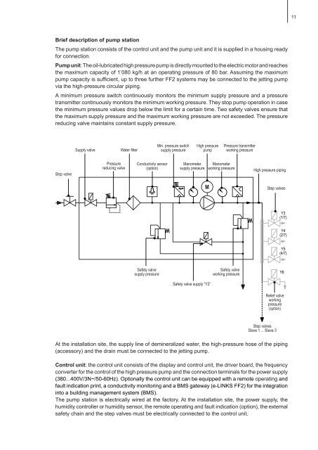
Brief description of pump station<br />
The pump station consists of the control unit and the pump unit and it is supplied in a housing ready<br />
for connection.<br />
Pump unit: The oil-lubricated high pressure pump is directly mounted to the electric motor and reaches<br />
the maximum capacity of 1’080 kg/h at an operating pressure of 80 bar. Assuming the maximum<br />
pump capacity is sufficient, up to three further <strong>FF2</strong> systems may be connected to the jetting pump<br />
via the high-pressure circular piping.<br />
A minimum pressure switch continuously monitors the minimum supply pressure and a pressure<br />
transmitter continuously monitors the minimum working pressure. They stop pump operation in case<br />
the minimum pressure values drop below the limit for a certain time. Two safety valves ensure that<br />
the maximum supply pressure and the maximum working pressure are not exceeded. The pressure<br />
reducing valve maintains constant supply pressure.<br />
Supply valve<br />
Water filter<br />
Min. pressure switch<br />
supply pressure<br />
High pressure<br />
pump<br />
Pressure transmitter<br />
working pressure<br />
Stop valve<br />
Pressure<br />
reducing valve<br />
Conductivity sensor<br />
(option)<br />
Manometer<br />
supply pressure<br />
Manometer<br />
working pressure<br />
High pressure piping<br />
M<br />
Step valves<br />
Safety valve<br />
supply pressure<br />
Safety valve<br />
working pressure<br />
Y6<br />
Safety valve supply “Y2”<br />
Relief valve<br />
working<br />
pressure<br />
(option)<br />
Step valves<br />
Slave 1 ... Slave 3<br />
At the installation site, the supply line of demineralized water, the high-pressure hose of the piping<br />
(accessory) and the drain must be connected to the jetting pump.<br />
Control unit: the control unit consists of the display and control unit, the driver board, the frequency<br />
converter for the control of the high pressure pump and the connection terminals for the power supply<br />
(380...400V/3N~/50-60Hz). Optionally the control unit can be equipped with a remote operating and<br />
fault indication print, a conductivity monitoring and a BMS gateway (e-LINKS <strong>FF2</strong>) for the integration<br />
into a building management system (BMS).<br />
The pump station is electrically wired at the factory. At the installation site, the power supply, the<br />
humidity controller or humidity sensor, the remote operating and fault indication (option), the external<br />
safety chain and the step valves must be electrically connected to the control unit.