AP2257 - Draft A1 - Machined Part Modelling for CATIA V5
AP2257 - Draft A1 - Machined Part Modelling for CATIA V5
AP2257 - Draft A1 - Machined Part Modelling for CATIA V5

You also want an ePaper? Increase the reach of your titles
YUMPU automatically turns print PDFs into web optimized ePapers that Google loves.
AIRBUS<br />
<strong>Machined</strong> <strong>Part</strong> <strong>Modelling</strong> <strong>for</strong> <strong>CATIA</strong> <strong>V5</strong><br />
<strong>AP2257</strong><br />
(C3)<br />
Sketch plan<br />
(P1)<br />
(L4)<br />
Resources<br />
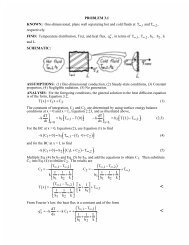
- Dp, the tool profile, construction (see figure ‘Resulting sketch’):<br />
! All the geometry at this step is defined in construction mode<br />
• Create a sketch (Sk1) with (P1) as support.<br />
• L5 coincident with (C3).<br />
• 0.3 mm offset to obtain L2.<br />
• L31 coincident with L3.<br />
• Construction of circle with radius R1. 3 constraints are associated: tangent to<br />
L21, L31 and radius of 4 mm.<br />
• Construction of Dp from the 2 constraints, a direction, here, vertical and tangent<br />
to the circle of radius R1.<br />
- Offset computation to create the pocket limit surface<br />
" Compute the offset between (Dp) and L5 (equal to C3) on the pocket plane Z=4.5 mm<br />
• Trim the different element to obtain the 2 points (Po1) and (Po2)<br />
• Compute the messier between these 2 elements<br />
# We find 0.62mm as offset distance<br />
Issue:<strong>Draft</strong> <strong>A1</strong> Date: 13 February 2002 Page 31 of 46