AP2257 - Draft A1 - Machined Part Modelling for CATIA V5
AP2257 - Draft A1 - Machined Part Modelling for CATIA V5
AP2257 - Draft A1 - Machined Part Modelling for CATIA V5

Create successful ePaper yourself
Turn your PDF publications into a flip-book with our unique Google optimized e-Paper software.
AIRBUS<br />
<strong>Machined</strong> <strong>Part</strong> <strong>Modelling</strong> <strong>for</strong> <strong>CATIA</strong> <strong>V5</strong><br />
<strong>AP2257</strong><br />
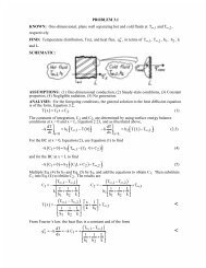
After having positioned<br />
one in relation to the<br />
other, you can define a<br />
distance constraint<br />
Intersection curve<br />
between the bottom of<br />
the pocket and the<br />
element<br />
The 2 contours are<br />
positioned relatively via<br />
a concentricity<br />
constraint<br />
Positioning of boss contour<br />
Boss contour<br />
• Once the contour has been correctly positioned, create a 3.2 mm thick "pad".<br />
- Creation of the hole or a pocket associated with the boss<br />
! Create a hole or pocket feature according to the size of the element. This definition is<br />
related to the machining process that used later, adapted to suit a pocket or a hole. On<br />
account of the dimensions, choose to define this feature as a pocket.<br />
• Define the contour of the hole taking position in relation to the previous sketch.<br />
Positioning of pocket contour<br />
Issue:<strong>Draft</strong> <strong>A1</strong> Date: 13 February 2002 Page 41 of 46