Low NOx
Low NOx
Low NOx
- No tags were found...

Create successful ePaper yourself
Turn your PDF publications into a flip-book with our unique Google optimized e-Paper software.
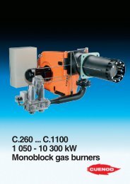
- mark gas burners<br />
C.75 – C.100<br />
335 - 1040kW.<br />
<strong>Low</strong> NO x
Standard clamp<br />
Electronic ignition<br />
transformer<br />
Combustion head<br />
(3 available<br />
lengths)<br />
Control and indicator panel:<br />
- Local/distance Start/Stop<br />
switch<br />
- Auto/Manual switch<br />
- Decrease/Increase of power<br />
- Panel<br />
Optional:<br />
- Ballast PID<br />
Fan motor<br />
Security and control unit<br />
MDE ® System<br />
Air shutter servomotor<br />
Isolated air unit<br />
Ventilated air compartment<br />
Painted aluminium alloy housing<br />
Ionization measuring point<br />
electrical compartment<br />
RS.232 socket<br />
Variatron ® (optional)<br />
Innovative technology to control<br />
energy.<br />
Medium output burners used in heating<br />
systems must meet five essential<br />
requirements:<br />
- simple implementation,<br />
- easy operation,<br />
- reliable and efficient settings,<br />
- rational use of energy,<br />
- low pollution emissions.<br />
The C.75 – C.100 burners are<br />
equipped with the innovative MDE ®<br />
system, which allows technicians to<br />
query the burner at any time and obtain<br />
operating information and details of<br />
startup phases.<br />
Burners with separate compartments<br />
combine our experience in designing<br />
domestic appliances with our skills in<br />
producing "medium output" equipment.<br />
A comprehensive control panel on<br />
the front of the burner contains the<br />
pressure regulator and the MDE ®<br />
system display. We recommend that<br />
these burners be used with the<br />
Variatron ® system.<br />
The burners function using modulating<br />
delivery air with natural gas and<br />
propane. They are designed to be<br />
installed on all types of boiler used in<br />
residential, tertiary and industrial<br />
buildings.<br />
Burners are designed, developed and<br />
built in compliance with the European<br />
standards EN 676.<br />
CUENOD burners bear the mark<br />
and meet the requirements of<br />
European Directives.<br />
73/23/EEC = <strong>Low</strong> Voltage<br />
89/336/EEC = Electromagnetic<br />
compatibility<br />
89/392/EEC = Machinery<br />
90/396/EEC = Gas appliances<br />
92/42/EEC = Efficiency requirements<br />
for new mark hot water boilers.<br />
CUENOD burners are made according<br />
to the quality assurance requirements<br />
of ISO 9001, certified by AFAQ.
<strong>Low</strong> <strong>NOx</strong><br />
The RTC ® system.<br />
The combination of a functional<br />
housing design, advanced combustion<br />
head technology and Memorized Head<br />
Settings (RTC ® ) ensures:<br />
• Total access,<br />
• Quick and easy maintenance,<br />
•<br />
Complete disassembly of all<br />
combustion head components (short,<br />
medium and long) in a single action<br />
without having to remove the burner,<br />
•<br />
Memorization of all optimised startup<br />
combustion settings during<br />
maintenance procedures.<br />
The AGP ® system.<br />
Developed and perfected by CUENOD,<br />
the AGP ® system has already won over<br />
gas combustion specialists. The system<br />
is fitted onto all our medium and high<br />
output burners.<br />
With this technology, burners guarantee:<br />
• a completely stable air-gas mix,<br />
• a high and constant CO 2 rate at all<br />
burner output levels,<br />
•<br />
accurate control of excess air,<br />
essentially for the optimum running of<br />
condensation generators.<br />
The AGP ® system also automatically<br />
corrects the following:<br />
• positive and negative gas pressure<br />
variations,<br />
• changes in air pressure due to<br />
electrical circuit voltage fluctuations<br />
and atmospheric pressure changes,<br />
• output according to pressure<br />
variations in the combustion<br />
chamber, especially during ignition.<br />
<strong>Low</strong> <strong>NOx</strong> combustion head.<br />
•<br />
The patented head design uses a<br />
combustion air pre-rotation system that<br />
increases air speed, homogenises the<br />
mix and reduces the time combustion<br />
products are in the flame, thus<br />
reducing thermal nitric oxide formation.<br />
•<br />
The use of natural gas reduces the<br />
amount of <strong>NOx</strong> produced to values of<br />
up to 80mg/kWh - in compliance with<br />
class 3 requirements of EN 676 - for<br />
the majority of standard-sized boilers<br />
(contact us for details).<br />
Air<br />
Combustion chamber<br />
Opening<br />
control<br />
Gas<br />
Ratio adjustment<br />
Principle of the AGP ® System
Air intake.<br />
Ventilation compartment ®<br />
The new high-performance internal<br />
recycling ventilation system, makes<br />
these burners highly adaptable on all<br />
boilers, enabling:<br />
• Faster combustion stabilization<br />
during startup.<br />
•<br />
Reduced pollution emission in<br />
compliance with European<br />
regulations.<br />
• Extremely low noise level (isolated<br />
air system) that can be further<br />
reduced through the use of an<br />
optional louvre.<br />
• Thermal output between 90 and<br />
94%, according to the type of boiler.<br />
In addition, the linear air shutter (volet<br />
d’air ® ) simplifies and improves<br />
adjustments.<br />
Main air<br />
intake.<br />
Multiple air intakes cool the fan motor<br />
and ensure a continuous supply of<br />
combustion air.<br />
Integrated electrical ®<br />
compartment<br />
Air intake.<br />
The electrical components are installed<br />
in a compartment isolated from the air<br />
circulation and dust. This ensures that<br />
these burners are IP 54 compliant.<br />
These burners are IP 54 only with the<br />
transparent plastic cover.<br />
This highly accessible compartment<br />
contains:<br />
• security box,<br />
• ionization current measuring point,<br />
• RS.232 socket,<br />
• motor-fan contact switch,<br />
• air shutter servomotor,<br />
• ignition transformer,<br />
• terminal board and automatic control<br />
switches,<br />
• nine cable entries with cable glands,<br />
• space to insert the speed variator:<br />
Variatron ® ,<br />
•<br />
control panel seen through a<br />
detachable window, including:<br />
Start-Stop switch, local-distance<br />
switches, Auto-Manu, pushbutton for<br />
manual output adjustment and<br />
control circuit fuse,<br />
• position for output regulator,<br />
•<br />
real-time display screen showing<br />
data from the MDE ® system.
<strong>Low</strong> <strong>NOx</strong><br />
Easy installation.<br />
The unique design and researched<br />
packaging provides:<br />
• Quick and reliable generator<br />
compatibility.<br />
• Significantly quicker assembly.<br />
• Precise, faultless connections.<br />
• Rack assembly without the need for<br />
any additional procedures: assembly<br />
and air-tightness inspection are<br />
carried out in the factory.<br />
• Accurate adjustment using clear and<br />
precise combustion head and<br />
servomotor markings.<br />
Optimal efficiency.<br />
•<br />
The advanced housing design and<br />
separate air and electrical systems<br />
provide full access to all<br />
components.<br />
• All electrical components use plugand-socket<br />
connections.<br />
The MDE ® system:<br />
Operating Data Memorization.<br />
Burners are equipped with a new<br />
operating system that may be<br />
consulted at any time. The system<br />
provides two types of data:<br />
1 — "Instantaneous" information<br />
- burner startup cycle<br />
- power supply measurement,<br />
- flame signal measurement.<br />
2 — "Stored" information<br />
- Burner operation data,<br />
including operating time<br />
- conditions of use procedures.<br />
This information, available in real<br />
time, can be exported and referenced<br />
using a laptop computer running<br />
Cuenocom software. The information<br />
can then be sent to the operating<br />
system to facilitate maintenance.<br />
This information is available on the<br />
front panel of the burner or may be<br />
obtained remotely using a modem.
Performance charts.<br />
daPa<br />
80<br />
60<br />
40<br />
20<br />
0<br />
C.75 GX 507 p20/25<br />
mbar<br />
0<br />
100 300 500 700 900 1100 kW<br />
140 335 750<br />
C.75 GX 507/8 p37-148-300<br />
daPa<br />
mbar<br />
8<br />
6<br />
4<br />
2<br />
daPa<br />
80<br />
60<br />
40<br />
20<br />
0<br />
C.100 GX 507 p20/25<br />
mbar<br />
0<br />
100 300 500 700 900 1100 kW<br />
170 520 1040<br />
C.100 GX 507/8 p37-148-300<br />
daPa<br />
mbar<br />
8<br />
6<br />
4<br />
2<br />
Packing.<br />
The burner is delivered in three<br />
separately packaged palettes weighing<br />
between 74 and 79kg depending on<br />
the model.<br />
• Burner body:<br />
- Integrated electrical bearing plate,<br />
- Boiler plate,<br />
- Documentation, including:<br />
- operating instructions,<br />
- electrical and hydraulic<br />
diagrams,<br />
- certificate of guarantee.<br />
• Combustion head:<br />
- front boiler attachment, a set of<br />
fasteners.<br />
• Gas rack:<br />
- valve set and collector.<br />
80<br />
8<br />
80<br />
8<br />
60<br />
6<br />
60<br />
6<br />
40<br />
4<br />
40<br />
4<br />
Front panel boring.<br />
20<br />
2<br />
20<br />
2<br />
0<br />
0<br />
100 300 500 700 900 1100 kW<br />
140 335 750<br />
Output levels.<br />
0<br />
0<br />
100 300 500 700 900 1100 kW<br />
170 530 1040<br />
Ø 260max<br />
Ø 195<br />
C.75 49 AQ 0924 C.100 49 AQ 0925<br />
20/25 37/148 300 20/25 37/148 300<br />
Output KW mbar mbar mbar mbar mbar mbar<br />
min max min max min max min max<br />
Burner (kW) 335 680 750 750 530 720 1040 1040<br />
Min. 1 st startup (kW) 140 — — — 170 — — —<br />
Boiler (kW) 310 625 690 690 490 665 960 960<br />
In bold, recommended ø.<br />
Bulk and dimensions.<br />
valve<br />
A minimum of 0.80m must be allowed<br />
on either side of the burner for<br />
maintenance purposes.<br />
Ventilation in the boiler room.<br />
1.2m 3 of new air is required for every<br />
kWh produced by the burner.<br />
Gas rack.<br />
The rack can only be installed<br />
horizontally, to the right or left.<br />
Note:<br />
The burner may be installed with the<br />
casing at the top or bottom.
<strong>Low</strong> <strong>NOx</strong><br />
Installation.<br />
The supply piping section is calculated to<br />
restrict energy loss to between 0.5 and<br />
1mbar at gas pressures of 20 and<br />
37mbar, and between 5 and 10mbar at<br />
pressures of 150 and 300mbar, without<br />
affecting the pressure regulator station.<br />
The piping diameter must be greater<br />
than the filter diameter.<br />
The following information shows the gas<br />
flows that correspond to the maximum<br />
burner output, at 15°C and 1013mbar.<br />
Gas flows.<br />
Flow in m 3 /h C.75 GX C.100 GX<br />
20/25 37/148 300 20/25 37/148 300<br />
mbar mbar mbar mbar mbar mbar<br />
Gas type min max min max min max min max<br />
Nominal gas flow<br />
at 15°C and 1013 mbar<br />
Natural group H m 3 /h 35 72 — 79 56 76 — 110<br />
Hi = 9,45 KWh/m 3<br />
Natural group L m 3 /h 41 79 — 92 65 88 — 103<br />
Hi = 8,13 KWh/m 3<br />
Propane P m 3 /h 14 — 31 — 22 — 43 —<br />
Hi = 24,44 KWh/m 3<br />
Density kg/m 3 = 1,98<br />
The gas rack is prewired and factorytested.<br />
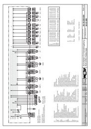
Hydraulic diagram.<br />
Air<br />
Gas<br />
Key:<br />
F4 Min. gas pressure switch<br />
F6 Air pressure switch<br />
M1 Fan motor<br />
T2 Ignition transformer<br />
Y10 Air shutter servomotor<br />
Y13 Main gas valve<br />
Y15 Safety gas valve<br />
101 Fan<br />
103 Air shutter<br />
106 Filter<br />
110 Gas injector<br />
119.1 Gas pressure point<br />
119.2 Combustion chamber pressure<br />
point<br />
119.3 Air pressure point<br />
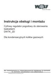
Electrical connection.<br />
Electrical installations must be carried out<br />
according to standard NF C 15.100<br />
and other standards currently in force.<br />
Particular attention must be paid to the<br />
burner supply main disconnect switch<br />
which must be able to carry the total<br />
circuit output and isolate the power and<br />
control circuits during maintenance.<br />
- from the power circuit:<br />
between L1, L2 and L3 terminals.<br />
This circuit must be protected using<br />
AM fuses.<br />
Power supply.<br />
Power supply connection:<br />
(see diagram).<br />
- from the control circuit: between the N<br />
(neutral) and L1 (live) terminals.<br />
In the interests of safety, an isolating<br />
transformer and a 30mA differential<br />
circuit breaker should be used when a<br />
230V three-phase power supply is<br />
used.<br />
This circuit must be protected using a<br />
10A fuse.<br />
Burner<br />
Motor output and three-phase circuit protection.<br />
Burner C.75 GX C.100 GX<br />
Motor output kW 1,1 1,5<br />
230V or 400V fuse A 10 10
<strong>Low</strong> <strong>NOx</strong><br />
Output adjustment.<br />
Operation.<br />
After startup (which uses approx. 15%<br />
of the normal flow), the thermal output<br />
progressively increases through two<br />
different flows.<br />
These can be adjusted to:<br />
- “Full” or “off”: progressive output<br />
increase (between 20 and 30<br />
seconds).<br />
The equipment benefits from all the<br />
combustion control of the AGP ®<br />
system.<br />
- “Full” or “low”: this type of setting<br />
offers not only the advantages of the<br />
AGP ® system, but saves energy by<br />
operating at reduced power.<br />
- “Modulating”: the power can be<br />
adapted to requirements. High<br />
performance installations offer a<br />
wide range of options:<br />
- adjustment of generator<br />
temperature to suit atmospheric<br />
conditions or to an existing setting.<br />
- adjustment to a required constant or<br />
variable temperature,<br />
- parallel adjustment of several<br />
generators to suit a decreasing or<br />
constant temperature,<br />
- cascade burner, pump and boiler<br />
adjustment for a temperature that is<br />
constant, variable, etc…<br />
Setting connection.<br />
- Connect terminals 84 and 85 for “full”<br />
flow or “off”.<br />
- Use the three-wire contact instruments<br />
for a “full” or “low” flow controlled by a<br />
thermostat or pressure switch.<br />
- A kit is provided with a prewired fusebase<br />
for a “Modulating” flow using an<br />
RC.40 or RC.6170 regulator. The<br />
control system is mounted on the<br />
control panel in the position reserved<br />
for this purpose.<br />
Using a standard electronic regulator<br />
(PID): this type of regulator is mounted<br />
in the standardized position reserved<br />
for this purpose (48 x 48 or 48 x 96).<br />
Note: The RC.40 or RC.6170 and the<br />
“alarm” output on certain regulators<br />
control operation.<br />
Imprimé en Italie par Musumeci Industrie Grafiche S.p.A.<br />
We reserve the right to upgrade equipment where required.<br />
10/2003 - EN