English Edition (6 MB pdf) - Saudi Aramco
English Edition (6 MB pdf) - Saudi Aramco
English Edition (6 MB pdf) - Saudi Aramco

Create successful ePaper yourself
Turn your PDF publications into a flip-book with our unique Google optimized e-Paper software.
Wellbore cleanup trips had been made in the early MSS<br />
deployments for <strong>Saudi</strong> <strong>Aramco</strong>. The likelihood that foreign<br />
objects in the wellbore were causing the deployment issues of<br />
the MSSs in <strong>Saudi</strong> <strong>Aramco</strong> wells was considered low.<br />
Ledges<br />
Wellbores are typically drilled with a drill bit then reamed<br />
with a watermelon-type mill. Drill bits can “deflect” when<br />
encountering harder formations or after making connections.<br />
This deflection can result in “steps” in the wellbore, which are<br />
easy for the bit and watermelon mill to negotiate, but difficult<br />
for the much stiffer liner pipe and tools, Figs. 3 and 4. A<br />
completion assembly is normally much stiffer than a drilling<br />
assembly, and typically contains tools with a larger outside<br />
diameter (OD).<br />
Ledges are also more common where the well is drilled in<br />
the minimum in-situ stress direction crossing several fracture<br />
planes or faults. Ledges can occur in areas where the fracture<br />
planes are crossed resulting in minor break outs of the<br />
formation face. In the case of the early wells drilled for the<br />
MSSs in <strong>Saudi</strong> <strong>Aramco</strong>, the wells were drilled in the maximum<br />
in-situ stress (i.e., parallel to the fracture plane).<br />
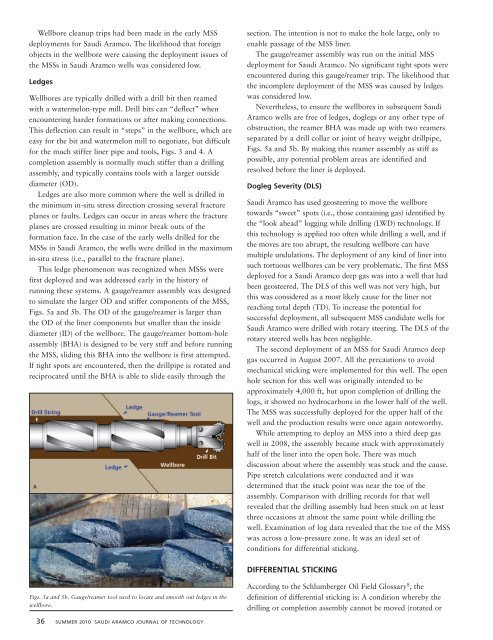
This ledge phenomenon was recognized when MSSs were<br />
first deployed and was addressed early in the history of<br />
running these systems. A gauge/reamer assembly was designed<br />
to simulate the larger OD and stiffer components of the MSS,<br />
Figs. 5a and 5b. The OD of the gauge/reamer is larger than<br />
the OD of the liner components but smaller than the inside<br />
diameter (ID) of the wellbore. The gauge/reamer bottom-hole<br />
assembly (BHA) is designed to be very stiff and before running<br />
the MSS, sliding this BHA into the wellbore is first attempted.<br />
If tight spots are encountered, then the drillpipe is rotated and<br />
reciprocated until the BHA is able to slide easily through the<br />
section. The intention is not to make the hole large, only to<br />
enable passage of the MSS liner.<br />
The gauge/reamer assembly was run on the initial MSS<br />
deployment for <strong>Saudi</strong> <strong>Aramco</strong>. No significant tight spots were<br />
encountered during this gauge/reamer trip. The likelihood that<br />
the incomplete deployment of the MSS was caused by ledges<br />
was considered low.<br />
Nevertheless, to ensure the wellbores in subsequent <strong>Saudi</strong><br />
<strong>Aramco</strong> wells are free of ledges, doglegs or any other type of<br />
obstruction, the reamer BHA was made up with two reamers<br />
separated by a drill collar or joint of heavy weight drillpipe,<br />
Figs. 5a and 5b. By making this reamer assembly as stiff as<br />
possible, any potential problem areas are identified and<br />
resolved before the liner is deployed.<br />
Dogleg Severity (DLS)<br />
<strong>Saudi</strong> <strong>Aramco</strong> has used geosteering to move the wellbore<br />
towards “sweet” spots (i.e., those containing gas) identified by<br />
the “look ahead” logging while drilling (LWD) technology. If<br />
this technology is applied too often while drilling a well, and if<br />
the moves are too abrupt, the resulting wellbore can have<br />
multiple undulations. The deployment of any kind of liner into<br />
such tortuous wellbores can be very problematic. The first MSS<br />
deployed for a <strong>Saudi</strong> <strong>Aramco</strong> deep gas was into a well that had<br />
been geosteered. The DLS of this well was not very high, but<br />
this was considered as a most likely cause for the liner not<br />
reaching total depth (TD). To increase the potential for<br />
successful deployment, all subsequent MSS candidate wells for<br />
<strong>Saudi</strong> <strong>Aramco</strong> were drilled with rotary steering. The DLS of the<br />
rotary steered wells has been negligible.<br />
The second deployment of an MSS for <strong>Saudi</strong> <strong>Aramco</strong> deep<br />
gas occurred in August 2007. All the precautions to avoid<br />
mechanical sticking were implemented for this well. The open<br />
hole section for this well was originally intended to be<br />
approximately 4,000 ft, but upon completion of drilling the<br />
logs, it showed no hydrocarbons in the lower half of the well.<br />
The MSS was successfully deployed for the upper half of the<br />
well and the production results were once again noteworthy.<br />
While attempting to deploy an MSS into a third deep gas<br />
well in 2008, the assembly became stuck with approximately<br />
half of the liner into the open hole. There was much<br />
discussion about where the assembly was stuck and the cause.<br />
Pipe stretch calculations were conducted and it was<br />
determined that the stuck point was near the toe of the<br />
assembly. Comparison with drilling records for that well<br />
revealed that the drilling assembly had been stuck on at least<br />
three occasions at almost the same point while drilling the<br />
well. Examination of log data revealed that the toe of the MSS<br />
was across a low-pressure zone. It was an ideal set of<br />
conditions for differential sticking.<br />
DIFFERENTIAL STICKING<br />
Figs. 5a and 5b. Gauge/reamer tool used to locate and smooth out ledges in the<br />
wellbore.<br />
According to the Schlumberger Oil Field Glossary 8 , the<br />
definition of differential sticking is: A condition whereby the<br />
drilling or completion assembly cannot be moved (rotated or<br />
36 SUMMER 2010 SAUDI ARAMCO JOURNAL OF TECHNOLOGY