English Edition (6 MB pdf) - Saudi Aramco
English Edition (6 MB pdf) - Saudi Aramco
English Edition (6 MB pdf) - Saudi Aramco

Create successful ePaper yourself
Turn your PDF publications into a flip-book with our unique Google optimized e-Paper software.
needed a fit-for-purpose bit design to match the system and to<br />
increase the steerability and stability, which were the weak<br />
points indentified in the first run with the PRSS. The first step<br />
included an in-depth analysis of Bit A to identify its strengths<br />
and weaknesses, and to establish an action plan for the next<br />
iteration. Among the strong points, it was clear that the use of<br />
eight blades and 19 mm cutters as the primary cutting<br />
structure provided a good balance between bit life and ROP;<br />
consequently, it was decided to continue with this geometry.<br />
Bit A recorded several vibration incidents, with slip-stick<br />
recorded at the surface and measured while drilling (MWD)<br />
shocks registered by the downhole tools. The cutters exhibited<br />
medium wear, and several chipped cutters indicated a need for<br />
improvements in the cutting structure. The force imbalance<br />
values, which were one of the few analytical components<br />
initially available when Bit B was designed, showed relatively<br />
high values. The ideal bit force imbalance scenario occurs<br />
when the values are near zero; values of less than 4% are<br />
accepted as the minimum standard.<br />
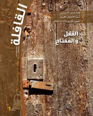
The cutting structure of the new Bit B included few<br />
changes, as compared with Bit A. To gain stability and<br />
improve the force imbalance values, the angle of the back<br />
rakes was adjusted by 15% to decrease the aggressiveness,<br />
and the blades were moved to obtain better figures. The 13<br />
mm cutters were eliminated in the bit face to increase the<br />
ROP, and the gauge length was reduced to 2½” to improve<br />
the steerability, particularly because planned future wells<br />
would require a greater BUR than the first two runs in the<br />
Haradh field. Rather than a straight gauge pad, Bit B used a<br />
spiral gauge, which considerably increased the borehole<br />
contact, Fig. 12.<br />
The cutter type in Bit B was updated to the Z3 ® cutter,<br />
which provided additional impact resistance. All force<br />
imbalance values were improved by up to 50%.<br />
Bit B was used in the next four wells, including two wells in<br />
the Haradh zone and two in the ‘Uthmaniyah zone. The 12”<br />
section in the ‘Uthmaniyah wells required building the angle<br />
from the vertical up to 74°, which tested the system’s<br />
steerability. In the first three wells of this batch, the 12”<br />
directional section was completed with one bit, but because of<br />
a long directional section in the last ‘Uthmaniyah well, the<br />
ROP became too low before the interval was completed,<br />
requiring the bit to be pulled out of the hole and the use of<br />
one more bit to complete the interval. Bit B showed better<br />
stability than Bit A; the steerability was good but not<br />
optimum because the PRSS had to be set at the maximum<br />
deflection in some intervals to achieve the required doglegs.<br />
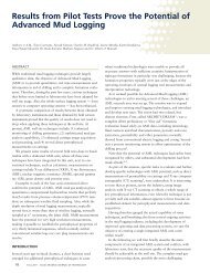
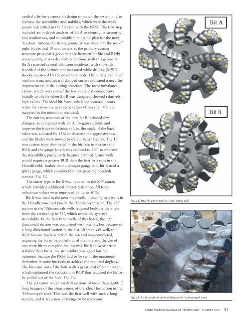
The bit came out of the hole with a great deal of cutter wear,<br />
which explained the reduction in ROP that required the bit to<br />
be pulled out of the hole, Fig. 13.<br />
The Z3 cutter could not drill sections of more than 2,500 ft<br />
long because of the abrasiveness of the Khuff formation in the<br />
‘Uthmaniyah zone. This was the first well with such a long<br />
section, and it set a new challenge to be overcome.<br />
Fig. 12. Straight gauge pad vs. spiral gauge pad.<br />
Fig. 13. Bit B condition after drilling in the ‘Uthmaniyah zone.<br />
SAUDI ARAMCO JOURNAL OF TECHNOLOGY SUMMER 2010 51