ECEN 454 â Lab1: Introduction to Cadence Schematic Capture ...
ECEN 454 â Lab1: Introduction to Cadence Schematic Capture ...
ECEN 454 â Lab1: Introduction to Cadence Schematic Capture ...

Create successful ePaper yourself
Turn your PDF publications into a flip-book with our unique Google optimized e-Paper software.
<strong>ECEN</strong> <strong>454</strong> – <strong>Lab1</strong>: <strong>Introduction</strong> <strong>to</strong> <strong>Cadence</strong> <strong>Schematic</strong> <strong>Capture</strong> &<br />
Simulation<br />
3. Simulation<br />
To make sure the schematic we just completed works properly, we will simulate it using<br />
Verilog-XL logic simula<strong>to</strong>r. Note that this is just the logic simulation of schematic and<br />
it does not give out accurate timing information (in fact, assuming zero gate delay<br />
model here).<br />
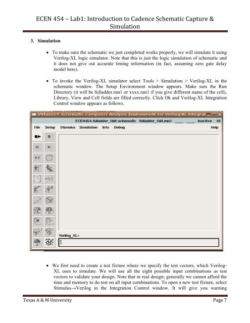
To invoke the Verilog-XL simula<strong>to</strong>r select Tools > Simulation > Verilog-XL in the<br />
schematic window. The Setup Environment window appears. Make sure the Run<br />
Direc<strong>to</strong>ry (it will be fulladder.run1 or xxxx.run1 if you give different name of the cell),<br />
Library, View and Cell fields are filled correctly. Click Ok and Verilog-XL Integration<br />
Control window appears as follows.<br />
We first need <strong>to</strong> create a test fixture where we specify the test vec<strong>to</strong>rs, which Verilog-<br />
XL uses <strong>to</strong> simulate. We will use all the eight possible input combinations as test<br />
vec<strong>to</strong>rs <strong>to</strong> validate your design. Note that in real design; generally we cannot afford the<br />
time and memory <strong>to</strong> do test on all input combinations. To open a new test fixture, select<br />
Stimulus→Verilog in the Integration Control window. It will give you warning<br />
Texas A & M University Page 7