Freedom SW 3000 Sine Wave Inverter/Charger - Xantrex
Freedom SW 3000 Sine Wave Inverter/Charger - Xantrex
Freedom SW 3000 Sine Wave Inverter/Charger - Xantrex

Create successful ePaper yourself
Turn your PDF publications into a flip-book with our unique Google optimized e-Paper software.
30 3614<br />
UL 458<br />
CSA 107.1-01<br />
Model<br />
Number<br />
FGA<br />
Number<br />
Designed in Canada<br />
A sembled in China<br />
TM<br />
TM<br />
<strong>3000</strong>W SINEWAVE INVERTER/CHARGER<br />
FR EDOM <strong>SW</strong> <strong>3000</strong><br />
F<strong>SW</strong><strong>3000</strong><br />
815-<strong>3000</strong><br />
<strong>Inverter</strong> Mode:<br />
Nominal DC Operating Voltage: 12 Vdc<br />
Nominal AC Output Voltage: 120 Vac , 1Ø<br />
Nominal AC Output Frequency: 60 Hz<br />
Max. Continuous AC Output Cu rent: 25 A<br />
Max. Operating DC Input Cu rent: 320 A<br />
Max. Continuous AC Output at Nominal DC<br />
Input: 3 0 VA at 25°C<br />
Max. Output Surge Power (5 s duration): 6 0 VA<br />
Max. DC Input Voltage: 16 Vdc<br />
Max. Ambient Temperature: 50°C<br />
Nominal AC Input Voltage: 120 Vac , 60 Hz, 1Ø<br />
Power Factor: > 0.95<br />
Charging DC Output Voltage Range: 5.0 - 16.0 Vdc<br />
Max. Continuous Ba tery <strong>Charger</strong> DC Cu rent at<br />
Nominal AC Input: 150 A<br />
Max. AC Input Cu rent: 30 A per line Split Phase,<br />
30 A per line Dual<br />
<strong>Charger</strong> Mode:<br />
INSTALLATION REQUIREMENTS:<br />
Moun this inverter/charger only in the orientations<br />
specified in the insta lation guide provided.<br />
Serial Number<br />
FREEDOM <strong>SW</strong> <strong>3000</strong><br />
Xanbus Interface<br />
<strong>Inverter</strong><br />
Reset Enable <strong>Inverter</strong> AC/<br />
On Charge Fault<br />
FREEDOM <strong>SW</strong> <strong>3000</strong><br />
Xanbus Interface<br />
FREEDOM <strong>SW</strong> <strong>3000</strong><br />
<strong>Inverter</strong><br />
Reset Enable <strong>Inverter</strong> AC/<br />
On Charge Fault<br />
CAUTION: To reduce the risk o fire, do not<br />
cover or obstruct ventilation openings. Do not mount<br />
in a zero-clearance compartment. Overheating may<br />
result. Do not expose to rain or spray.<br />
FREEDOM <strong>SW</strong> <strong>3000</strong><br />
WARNING: Shock hazard. Do not open. No<br />
user serviceable parts. Energized from both AC and<br />
DC sources. Disco nect a l sources before servicing.<br />
Use only ground-fault circuit inte rupters (GFCI)<br />
specified in the insta lation guide su plied. Other<br />
Date of Manufacture<br />
types may fail to operate properly when co nected to<br />
this equipment. Refer to manual. Charge only<br />
lead-acid ba teries. Other ba tery types may burst<br />
causing personal injury and damage.<br />
DANGER: To reduce the risk of explosion, do not<br />
insta l in an area in which ignition-protected<br />
euipment is required.<br />
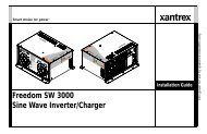
<strong>Freedom</strong> <strong>SW</strong> <strong>3000</strong><br />
<strong>Sine</strong> <strong>Wave</strong> <strong>Inverter</strong>/<strong>Charger</strong><br />
Owner’s Guide
About <strong>Xantrex</strong><br />
<strong>Xantrex</strong> Technology Inc. (www.xantrex.com), a subsidiary of Schneider Electric, is a<br />
world leader in the development, manufacturing and marketing of advanced power<br />
electronic products and systems for the renewable and mobile power markets. The<br />
company's products convert and control raw electrical power from any central,<br />
distributed, renewable, or backup power source into high-quality power required by<br />
electronic equipment and the electricity grid. <strong>Xantrex</strong> is headquartered in Vancouver,<br />
Canada, with facilities in the United States, Germany, Spain, and a joint venture in<br />
China.<br />
Trademarks<br />
<strong>Xantrex</strong> and Smart Choice for Power are trademarks of Schneider Electric<br />
International Services sprl, registered in the U.S. and other countries. Other<br />
trademarks, registered trademarks, and product names are the property of their<br />
respective owners and are used herein for identification purposes only.<br />
Notice of Copyright<br />
<strong>Freedom</strong> <strong>SW</strong> <strong>3000</strong> <strong>Sine</strong> <strong>Wave</strong> <strong>Inverter</strong>/<strong>Charger</strong> Owner’s Guide © January 2010<br />
<strong>Xantrex</strong> Technology Inc. All rights reserved. No part of this document may be<br />
reproduced in any form or disclosed to third parties without the express written<br />
consent of: <strong>Xantrex</strong> Technology Inc., 161-G South Vasco Road, Livermore,<br />
California, USA 94551. <strong>Xantrex</strong> Technology Inc. reserves the right to revise this<br />
document and to periodically make changes to the content hereof without obligation<br />
or organization of such revisions or changes unless required to do so by prior<br />
arrangement.<br />
Date and Revision<br />
January 2010 Rev A<br />
Document Part Number<br />
975-0545-01-01<br />
Product Number<br />
815-<strong>3000</strong><br />
Contact Information<br />
Telephone: 1 800 670 0707 (toll free North America)<br />
1 408 987 6030 (direct)<br />
Fax: 1 800 994 7828 (toll free North America)<br />
Email: customerservice@xantrex.com<br />
Web: www.xantrex.com<br />
Exclusion for Documentation<br />
UNLESS SPECIFICALLY AGREED TO IN WRITING, XANTREX TECHNOLOGY INC. (“XANTREX”)<br />
(A) MAKES NO WARRANTY AS TO THE ACCURACY, SUFFICIENCY OR SUITABILITY OF ANY<br />
TECHNICAL OR OTHER INFORMATION PROVIDED IN ITS MANUALS OR OTHER DOCUMENTATION;<br />
(B) ASSUMES NO RESPONSIBILITY OR LIABILITY FOR LOSSES, DAMAGES, COSTS OR EXPENSES,<br />
WHETHER SPECIAL, DIRECT, INDIRECT, CONSEQUENTIAL OR INCIDENTAL, WHICH MIGHT ARISE<br />
OUT OF THE USE OF SUCH INFORMATION. THE USE OF ANY SUCH INFORMATION WILL BE ENTIRELY<br />
AT THE USER’S RISK; AND<br />
(C) REMINDS YOU THAT IF THIS MANUAL IS IN ANY LANGUAGE OTHER THAN ENGLISH,<br />
ALTHOUGH STEPS HAVE BEEN TAKEN TO MAINTAIN THE ACCURACY OF THE TRANSLATION, THE<br />
ACCURACY CANNOT BE GUARANTEED. APPROVED XANTREX CONTENT IS CONTAINED WITH THE<br />
ENGLISH LANGUAGE VERSION WHICH IS POSTED AT WWW.XANTREX.COM.<br />
975-0545-01-01 i
About This Guide<br />
Purpose<br />
The purpose of this Owner’s Guide is to provide explanations and<br />
procedures for operating, troubleshooting, and maintaining the <strong>Freedom</strong><br />
<strong>SW</strong> <strong>3000</strong> <strong>Inverter</strong>/<strong>Charger</strong>.<br />
Scope<br />
The Guide provides safety and operating guidelines as well as information<br />
on configuring the inverter/charger. It also provides information about<br />
troubleshooting the unit. It does not provide details about particular brands<br />
of batteries. You need to consult individual battery manufacturers for this<br />
information.<br />
Audience<br />
The Guide is intended for users and operators of the <strong>Freedom</strong> <strong>SW</strong> <strong>3000</strong><br />
<strong>Inverter</strong>/<strong>Charger</strong>.<br />
Conventions Used<br />
The following conventions are used in this guide.<br />
STATEMENT OF HAZARD<br />
Contains statements of avoidance or strict compliance.<br />
Failure to follow these instructions will result in death or serious<br />
injury.<br />
ii<br />
STATEMENT OF HAZARD<br />
Contains statements of avoidance or strict compliance.<br />
Failure to follow these instructions can result in death or serious<br />
injury.<br />
STATEMENT OF HAZARD<br />
Contains statements of avoidance or strict compliance.<br />
Failure to follow these instructions can result in minor or moderate<br />
injury.<br />
STATEMENT OF HAZARD<br />
Contains statements of avoidance or strict compliance.<br />
Failure to follow these instructions can damage the unit and/or<br />
damage other equipment.<br />
IMPORTANT: These notes describe things which are important for you to<br />
know, however, they are not as serious as a caution or warning.<br />
<strong>Freedom</strong> <strong>SW</strong> <strong>3000</strong> Owner’s Guide
Related Information<br />
You can find more information about <strong>Xantrex</strong> Technology Inc. as well as<br />
its products and services at www.xantrex.com.<br />
NOTE: The Installation Guide (Document Part Number: 975-0546-01-01) is<br />
primarily intended for qualified installers who need to install and configure<br />
the <strong>Freedom</strong> <strong>SW</strong> <strong>3000</strong> <strong>Inverter</strong>/<strong>Charger</strong>. The installer should have<br />
knowledge and experience in installing electrical equipment, knowledge of<br />
the applicable installation codes, and awareness of the hazards involved in<br />
performing electrical work and how to reduce those hazards. A qualified<br />
technician or electrician has this knowledge and experience.<br />
975-0545-01-01 iii
Important Safety Instructions<br />
IMPORTANT: READ AND SAVE THIS OWNER’S GUIDE FOR FUTURE<br />
REFERENCE.<br />
This chapter contains important safety and installation instructions for the<br />
<strong>Freedom</strong> <strong>SW</strong> <strong>3000</strong> <strong>Inverter</strong>/<strong>Charger</strong> (<strong>Freedom</strong> <strong>SW</strong> <strong>3000</strong>). Each time,<br />
before using the <strong>Freedom</strong> <strong>SW</strong> <strong>3000</strong>, READ ALL instructions and<br />
cautionary markings on or provided with the inverter/charger, the batteries,<br />
and all appropriate sections of this guide.<br />
NOTE: The <strong>Freedom</strong> <strong>SW</strong> <strong>3000</strong> contains no user-serviceable parts. See<br />
“Warranty and Return Information” on page 65 for guidance.<br />
ELECTRICAL SHOCK HAZARD<br />
• Do not expose the <strong>Freedom</strong> <strong>SW</strong> <strong>3000</strong> to rain, snow, spray, or bilge<br />
water. This inverter/charger is designed for indoor use only.<br />
• Do not operate the inverter/charger if it has received a sharp blow,<br />
been dropped, has cracks or openings in the enclosure including if the<br />
fuse cover has been lost, damaged, or will not close, or otherwise<br />
damaged in any other way.<br />
• Do not disassemble the inverter/charger. Internal capacitors remain<br />
charged after all power is disconnected.<br />
• Disconnect both AC and DC power from the inverter/charger before<br />
attempting any maintenance or cleaning or working on any circuits<br />
connected to the inverter/charger. See note below.<br />
• Do not operate the inverter/charger with damaged or substandard<br />
wiring. Make sure that all wiring is in good condition and is not<br />
undersized.<br />
Failure to follow these instructions will result in death or serious<br />
injury.<br />
NOTE: Turning off the inverter/charger using the on/off switch on the front<br />
panel will not reduce an electrical shock hazard.<br />
iv<br />
<strong>Freedom</strong> <strong>SW</strong> <strong>3000</strong> Owner’s Guide
FIRE AND BURN HAZARD<br />
• Do not cover or obstruct the air intake vent openings and/or install in<br />
a zero-clearance compartment.<br />
• Do not use transformerless battery chargers in conjunction with the<br />
inverter/charger due to overheating.<br />
Failure to follow these instructions will result in death or serious<br />
injury.<br />
NOTES:<br />
1. Follow these instructions and those published by the battery<br />
manufacturer and the manufacturer of any equipment you intend to use<br />
in the vicinity of the battery. Review cautionary markings on these<br />
products and on the engine.<br />
2. This inverter/charger contains components which tend to produce arcs<br />
or sparks.<br />
3. Locations include any space containing gasoline-powered machinery,<br />
fuel tanks, as well as joints, fittings, or other connections between<br />
components of the fuel system.<br />
EXPLOSION HAZARD<br />
• Charge only properly rated (such as 12 V) lead-acid (GEL, AGM,<br />
Flooded, or lead-calcium) rechargeable batteries because other<br />
battery types may explode and burst.<br />
• Do not work in the vicinity of lead-acid batteries. Batteries generate<br />
explosive gases during normal operation. See note #1.<br />
• Do not install and/or operate in compartments containing flammable<br />
materials or in locations that require ignition-protected equipment.<br />
See notes #2 and #3.<br />
Failure to follow these instructions will result in death or serious<br />
injury.<br />
975-0545-01-01 v
Precautions When Working With Batteries<br />
BURN FROM HIGH SHORT-CIRCUIT CURRENT, FIRE AND EXPLO-<br />
SION FROM VENTED GASES HAZARDS<br />
• Always wear proper, non-absorbent gloves, complete eye protection,<br />
and clothing protection. Avoid touching your eyes and wiping your<br />
forehead while working near batteries. See note #4.<br />
• Remove all personal metal items, like rings, bracelets, and watches<br />
when working with batteries. See notes #5 and #6 below.<br />
• Never smoke or allow a spark or flame near the engine or batteries.<br />
• Never charge a frozen battery.<br />
Failure to follow these instructions can result in death or serious<br />
injury.<br />
5. Use extra caution to reduce the risk or dropping a metal tool on the<br />
battery. It could spark or short circuit the battery or other electrical<br />
parts and could cause an explosion.<br />
6. Batteries can produce a short circuit current high enough to weld a ring<br />
or metal bracelet or the like to the battery terminal, causing a severe<br />
burn.<br />
7. When removing a battery, always remove the negative terminal from<br />
the battery first for systems with grounded negative. If it is grounded<br />
positive, remove the positive terminal first. Make sure all loads<br />
connected to the battery and all accessories are off so you don’t cause<br />
an arc.<br />
NOTES:<br />
1. Mount and place the <strong>Freedom</strong> <strong>SW</strong> <strong>3000</strong> <strong>Inverter</strong>/<strong>Charger</strong> unit away<br />
from batteries in a well ventilated compartment.<br />
2. Always have someone within range of your voice or close enough to<br />
come to your aid when you work near a lead-acid battery.<br />
3. Always have plenty of fresh water and soap nearby in case battery acid<br />
contacts skin, clothing, or eyes.<br />
4. If battery acid contacts skin or clothing, wash immediately with soap<br />
and water. If acid enters your eye, immediately flood it with running<br />
cold water for at least twenty minutes and get medical attention<br />
immediately.<br />
vi<br />
<strong>Freedom</strong> <strong>SW</strong> <strong>3000</strong> Owner’s Guide
Precautions When Preparing to Charge<br />
Precautions When Placing the <strong>Inverter</strong>/<strong>Charger</strong><br />
EXPOSURE TO CHEMICALS AND GASES HAZARD<br />
• Make sure the area around the battery is well ventilated.<br />
• Make sure the voltage of the batteries matches the output voltage of<br />
the inverter/charger.<br />
• Be careful to keep corrosion from coming into contact with your eyes<br />
and skin when cleaning battery terminals.<br />
Failure to follow these instructions can result in death or serious<br />
injury.<br />
NOTES:<br />
• Study and follow all of the battery manufacturer's specific precautions,<br />
such as removing or not removing cell caps while charging, whether<br />
equalization is acceptable for your battery, and recommended rates of<br />
charge.<br />
• For flooded non-sealed batteries, add distilled water in each cell until<br />
battery acid reaches the level specified by the battery manufacturer.<br />
This helps to purge excessive gas from cells. Do not overfill. For a<br />
battery without removable cell caps, carefully follow manufacturer's<br />
instructions.<br />
RISK OF DAMAGE TO THE INVERTER/CHARGER<br />
• Never allow battery acid to drip on the inverter/charger when reading<br />
gravity, or filling battery.<br />
• Never place the <strong>Freedom</strong> <strong>SW</strong> <strong>3000</strong> <strong>Inverter</strong>/<strong>Charger</strong> unit directly<br />
above batteries; gases from a battery will corrode and damage the<br />
inverter/charger.<br />
• Do not place a battery on top of the inverter/charger.<br />
Failure to follow these instructions can damage the unit and/or<br />
damage other equipment.<br />
975-0545-01-01 vii
Regulatory<br />
The <strong>Freedom</strong> <strong>SW</strong> <strong>3000</strong> <strong>Inverter</strong>/<strong>Charger</strong> is certified to appropriate US and<br />
Canadian standards. For more information see “Regulatory Approvals” on<br />
page 63.<br />
The <strong>Freedom</strong> <strong>SW</strong> <strong>3000</strong> <strong>Inverter</strong>/<strong>Charger</strong> is intended to be used for<br />
residential or commercial applications. It is not intended for other<br />
applications as it may not comply with the additional safety code<br />
requirements needed for those other applications. See “Limitations On Use”<br />
below.<br />
LIMITATIONS ON USE<br />
• Do not use in connection with life support systems or other medical<br />
equipment or devices.<br />
• Do not use in ambulances or other life-saving emergency vehicles.<br />
Failure to follow these instructions can result in death or serious<br />
injury.<br />
viii<br />
<strong>Freedom</strong> <strong>SW</strong> <strong>3000</strong> Owner’s Guide
Contents<br />
Important Safety Instructions . . . . . . . . . . . . . . . . . . . . . . . . . . . . . . . . . . . . . . . . . . . . . . . . . . . . . . . . . . . . . . . . . . . . . . . . . . . . . . . . . . . . . iv<br />
Introduction . . . . . . . . . . . . . . . . . . . . . . . . . . . . . . . . . . . . . . . . . . . . . . . . . . . . . . . . . . . . . . . . . . . . . . . . . . . . . . . . . . . . . . . . . . . . . . . . . . . .1<br />
Materials List . . . . . . . . . . . . . . . . . . . . . . . . . . . . . . . . . . . . . . . . . . . . . . . . . . . . . . . . . . . . . . . . . . . . . . . . . . . . . . . . . . . . . . . . . . .1<br />
About the <strong>Freedom</strong> <strong>SW</strong> <strong>3000</strong><br />
<strong>Inverter</strong>/<strong>Charger</strong> . . . . . . . . . . . . . . . . . . . . . . . . . . . . . . . . . . . . . . . . . . . . . . . . . . . . . . . . . . . . . . . . . . . . . . . . . . . . . . . . . . . . . . . . . . . . . . . .2<br />
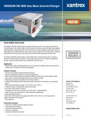
Premium Power and Ease of Use . . . . . . . . . . . . . . . . . . . . . . . . . . . . . . . . . . . . . . . . . . . . . . . . . . . . . . . . . . . . . . . . . . . . . . . . . . . .2<br />
How the <strong>Freedom</strong> <strong>SW</strong> <strong>3000</strong> <strong>Inverter</strong>/<strong>Charger</strong> Works . . . . . . . . . . . . . . . . . . . . . . . . . . . . . . . . . . . . . . . . . . . . . . . . . . . . . . . . . . . .3<br />
Inverting . . . . . . . . . . . . . . . . . . . . . . . . . . . . . . . . . . . . . . . . . . . . . . . . . . . . . . . . . . . . . . . . . . . . . . . . . . . . . . . . . . . . . . . . . . .3<br />
Charging . . . . . . . . . . . . . . . . . . . . . . . . . . . . . . . . . . . . . . . . . . . . . . . . . . . . . . . . . . . . . . . . . . . . . . . . . . . . . . . . . . . . . . . . . . .3<br />
Xanbus® System . . . . . . . . . . . . . . . . . . . . . . . . . . . . . . . . . . . . . . . . . . . . . . . . . . . . . . . . . . . . . . . . . . . . . . . . . . . . . . . . . . . . . . . .4<br />
Comprehensive Electronic Protection . . . . . . . . . . . . . . . . . . . . . . . . . . . . . . . . . . . . . . . . . . . . . . . . . . . . . . . . . . . . . . . . . . . . . . . .5<br />
<strong>Freedom</strong> <strong>SW</strong> <strong>3000</strong> <strong>Inverter</strong>/<strong>Charger</strong> Features. . . . . . . . . . . . . . . . . . . . . . . . . . . . . . . . . . . . . . . . . . . . . . . . . . . . . . . . . . . . . . . . . . . . . . . . . .6<br />
Front and Side Panels . . . . . . . . . . . . . . . . . . . . . . . . . . . . . . . . . . . . . . . . . . . . . . . . . . . . . . . . . . . . . . . . . . . . . . . . . . . . . . . . . . . . .6<br />
Front and Side Panels . . . . . . . . . . . . . . . . . . . . . . . . . . . . . . . . . . . . . . . . . . . . . . . . . . . . . . . . . . . . . . . . . . . . . . . . . . . . . . . . . . . . .7<br />
AC and DC Side Panels . . . . . . . . . . . . . . . . . . . . . . . . . . . . . . . . . . . . . . . . . . . . . . . . . . . . . . . . . . . . . . . . . . . . . . . . . . . . . . . . . . .9<br />
Supplied Accessories . . . . . . . . . . . . . . . . . . . . . . . . . . . . . . . . . . . . . . . . . . . . . . . . . . . . . . . . . . . . . . . . . . . . . . . . . . . . . . . . . . . .10<br />
Optional System Accessories and Network Components . . . . . . . . . . . . . . . . . . . . . . . . . . . . . . . . . . . . . . . . . . . . . . . . . . . . . . . .11<br />
Operating The <strong>Freedom</strong> <strong>SW</strong> <strong>3000</strong>. . . . . . . . . . . . . . . . . . . . . . . . . . . . . . . . . . . . . . . . . . . . . . . . . . . . . . . . . . . . . . . . . . . . . . . . . . . . . . . . . .12<br />
Operating the <strong>Freedom</strong> <strong>SW</strong> <strong>3000</strong> with the Optional System Control Panel (SCP) . . . . . . . . . . . . . . . . . . . . . . . . . . . . . . . . . . . . .12<br />
Using the SCP . . . . . . . . . . . . . . . . . . . . . . . . . . . . . . . . . . . . . . . . . . . . . . . . . . . . . . . . . . . . . . . . . . . . . . . . . . . . . . . . . . . . . . . . .13
On Start Up . . . . . . . . . . . . . . . . . . . . . . . . . . . . . . . . . . . . . . . . . . . . . . . . . . . . . . . . . . . . . . . . . . . . . . . . . . . . . . . . . . . . . . . . . . .14<br />
System Start-up Check . . . . . . . . . . . . . . . . . . . . . . . . . . . . . . . . . . . . . . . . . . . . . . . . . . . . . . . . . . . . . . . . . . . . . . . . . . . . . . . . . . .15<br />
Viewing the Firmware Revision Number . . . . . . . . . . . . . . . . . . . . . . . . . . . . . . . . . . . . . . . . . . . . . . . . . . . . . . . . . . . . . . . . . . . .15<br />
Operating in Invert Mode . . . . . . . . . . . . . . . . . . . . . . . . . . . . . . . . . . . . . . . . . . . . . . . . . . . . . . . . . . . . . . . . . . . . . . . . . . . . . . . . .16<br />
Operating Limits for <strong>Inverter</strong> Operation . . . . . . . . . . . . . . . . . . . . . . . . . . . . . . . . . . . . . . . . . . . . . . . . . . . . . . . . . . . . . . . . . .16<br />
Operating in <strong>Charger</strong> Mode . . . . . . . . . . . . . . . . . . . . . . . . . . . . . . . . . . . . . . . . . . . . . . . . . . . . . . . . . . . . . . . . . . . . . . . . . . . . . . .17<br />
<strong>Charger</strong> Operation with Battery Temperature<br />
Sensor (BTS) . . . . . . . . . . . . . . . . . . . . . . . . . . . . . . . . . . . . . . . . . . . . . . . . . . . . . . . . . . . . . . . . . . . . . . . . . . . . . . . . . . . . . . . . . . . . . . . . .17<br />
Operating in Equalization Mode . . . . . . . . . . . . . . . . . . . . . . . . . . . . . . . . . . . . . . . . . . . . . . . . . . . . . . . . . . . . . . . . . . . . . . . . . . .18<br />
Equalizing Batteries . . . . . . . . . . . . . . . . . . . . . . . . . . . . . . . . . . . . . . . . . . . . . . . . . . . . . . . . . . . . . . . . . . . . . . . . . . . . . . . . .19<br />
Terminating the Equalization Process . . . . . . . . . . . . . . . . . . . . . . . . . . . . . . . . . . . . . . . . . . . . . . . . . . . . . . . . . . . . . . . . . . .19<br />
Operating Limits for <strong>Charger</strong> Operation . . . . . . . . . . . . . . . . . . . . . . . . . . . . . . . . . . . . . . . . . . . . . . . . . . . . . . . . . . . . . . . . .20<br />
Monitoring the <strong>Freedom</strong> <strong>SW</strong> <strong>3000</strong> Indicator Lights . . . . . . . . . . . . . . . . . . . . . . . . . . . . . . . . . . . . . . . . . . . . . . . . . . . . . . . . . . . .21<br />
Faults and Warnings . . . . . . . . . . . . . . . . . . . . . . . . . . . . . . . . . . . . . . . . . . . . . . . . . . . . . . . . . . . . . . . . . . . . . . . . . . . . . . . . .21<br />
Monitoring Status Messages on the SCP . . . . . . . . . . . . . . . . . . . . . . . . . . . . . . . . . . . . . . . . . . . . . . . . . . . . . . . . . . . . . . . . .21<br />
System Modes . . . . . . . . . . . . . . . . . . . . . . . . . . . . . . . . . . . . . . . . . . . . . . . . . . . . . . . . . . . . . . . . . . . . . . . . . . . . . . . . . . . . . . . . .22<br />
Operating . . . . . . . . . . . . . . . . . . . . . . . . . . . . . . . . . . . . . . . . . . . . . . . . . . . . . . . . . . . . . . . . . . . . . . . . . . . . . . . . . . . . . . . . .22<br />
Safe . . . . . . . . . . . . . . . . . . . . . . . . . . . . . . . . . . . . . . . . . . . . . . . . . . . . . . . . . . . . . . . . . . . . . . . . . . . . . . . . . . . . . . . . . . . . . .23<br />
Configuration. . . . . . . . . . . . . . . . . . . . . . . . . . . . . . . . . . . . . . . . . . . . . . . . . . . . . . . . . . . . . . . . . . . . . . . . . . . . . . . . . . . . . . . . . . . . . . . . . .25<br />
System Control Panel . . . . . . . . . . . . . . . . . . . . . . . . . . . . . . . . . . . . . . . . . . . . . . . . . . . . . . . . . . . . . . . . . . . . . . . . . . . . . . . . . . . .25<br />
System Menu Map . . . . . . . . . . . . . . . . . . . . . . . . . . . . . . . . . . . . . . . . . . . . . . . . . . . . . . . . . . . . . . . . . . . . . . . . . . . . . . . . . . . . . .26<br />
Viewing the System Screen . . . . . . . . . . . . . . . . . . . . . . . . . . . . . . . . . . . . . . . . . . . . . . . . . . . . . . . . . . . . . . . . . . . . . . . . . . .27<br />
Viewing the Select Device Menu . . . . . . . . . . . . . . . . . . . . . . . . . . . . . . . . . . . . . . . . . . . . . . . . . . . . . . . . . . . . . . . . . . . . . . .27<br />
Selecting the <strong>Freedom</strong> <strong>SW</strong> <strong>3000</strong> from the Select Device Menu . . . . . . . . . . . . . . . . . . . . . . . . . . . . . . . . . . . . . . . . . . . . . . .28<br />
Selecting and Adjusting the Configurable Settings . . . . . . . . . . . . . . . . . . . . . . . . . . . . . . . . . . . . . . . . . . . . . . . . . . . . . . . . .30<br />
Selecting the Default Settings . . . . . . . . . . . . . . . . . . . . . . . . . . . . . . . . . . . . . . . . . . . . . . . . . . . . . . . . . . . . . . . . . . . . . . . . . .30
Menu Structure . . . . . . . . . . . . . . . . . . . . . . . . . . . . . . . . . . . . . . . . . . . . . . . . . . . . . . . . . . . . . . . . . . . . . . . . . . . . . . . . . . . . . . . . .31<br />
Device Menu . . . . . . . . . . . . . . . . . . . . . . . . . . . . . . . . . . . . . . . . . . . . . . . . . . . . . . . . . . . . . . . . . . . . . . . . . . . . . . . . . . . . . . . . . .31<br />
Modes . . . . . . . . . . . . . . . . . . . . . . . . . . . . . . . . . . . . . . . . . . . . . . . . . . . . . . . . . . . . . . . . . . . . . . . . . . . . . . . . . . . . . . . . . . . .31<br />
Battery . . . . . . . . . . . . . . . . . . . . . . . . . . . . . . . . . . . . . . . . . . . . . . . . . . . . . . . . . . . . . . . . . . . . . . . . . . . . . . . . . . . . . . . . . . . .32<br />
AC Input1 . . . . . . . . . . . . . . . . . . . . . . . . . . . . . . . . . . . . . . . . . . . . . . . . . . . . . . . . . . . . . . . . . . . . . . . . . . . . . . . . . . . . . . . . .32<br />
AC Out . . . . . . . . . . . . . . . . . . . . . . . . . . . . . . . . . . . . . . . . . . . . . . . . . . . . . . . . . . . . . . . . . . . . . . . . . . . . . . . . . . . . . . . . . . .32<br />
Menu (Basic) . . . . . . . . . . . . . . . . . . . . . . . . . . . . . . . . . . . . . . . . . . . . . . . . . . . . . . . . . . . . . . . . . . . . . . . . . . . . . . . . . . . . . . . . . .33<br />
<strong>Inverter</strong> . . . . . . . . . . . . . . . . . . . . . . . . . . . . . . . . . . . . . . . . . . . . . . . . . . . . . . . . . . . . . . . . . . . . . . . . . . . . . . . . . . . . . . . . . . .33<br />
<strong>Charger</strong> . . . . . . . . . . . . . . . . . . . . . . . . . . . . . . . . . . . . . . . . . . . . . . . . . . . . . . . . . . . . . . . . . . . . . . . . . . . . . . . . . . . . . . . . . . .33<br />
Power Share . . . . . . . . . . . . . . . . . . . . . . . . . . . . . . . . . . . . . . . . . . . . . . . . . . . . . . . . . . . . . . . . . . . . . . . . . . . . . . . . . . . . . . .33<br />
Equalize . . . . . . . . . . . . . . . . . . . . . . . . . . . . . . . . . . . . . . . . . . . . . . . . . . . . . . . . . . . . . . . . . . . . . . . . . . . . . . . . . . . . . . . . . .34<br />
Batt Type . . . . . . . . . . . . . . . . . . . . . . . . . . . . . . . . . . . . . . . . . . . . . . . . . . . . . . . . . . . . . . . . . . . . . . . . . . . . . . . . . . . . . . . . .37<br />
Batt Size . . . . . . . . . . . . . . . . . . . . . . . . . . . . . . . . . . . . . . . . . . . . . . . . . . . . . . . . . . . . . . . . . . . . . . . . . . . . . . . . . . . . . . . . . .37<br />
Clear Faults . . . . . . . . . . . . . . . . . . . . . . . . . . . . . . . . . . . . . . . . . . . . . . . . . . . . . . . . . . . . . . . . . . . . . . . . . . . . . . . . . . . . . . . .37<br />
Menu (Advanced) . . . . . . . . . . . . . . . . . . . . . . . . . . . . . . . . . . . . . . . . . . . . . . . . . . . . . . . . . . . . . . . . . . . . . . . . . . . . . . . . . . . . . .38<br />
<strong>Inverter</strong> . . . . . . . . . . . . . . . . . . . . . . . . . . . . . . . . . . . . . . . . . . . . . . . . . . . . . . . . . . . . . . . . . . . . . . . . . . . . . . . . . . . . . . . . . . .38<br />
<strong>Charger</strong> . . . . . . . . . . . . . . . . . . . . . . . . . . . . . . . . . . . . . . . . . . . . . . . . . . . . . . . . . . . . . . . . . . . . . . . . . . . . . . . . . . . . . . . . . . .38<br />
Power Share . . . . . . . . . . . . . . . . . . . . . . . . . . . . . . . . . . . . . . . . . . . . . . . . . . . . . . . . . . . . . . . . . . . . . . . . . . . . . . . . . . . . . . .38<br />
Configure Inv/Chg (Configure <strong>Inverter</strong>/<strong>Charger</strong>) . . . . . . . . . . . . . . . . . . . . . . . . . . . . . . . . . . . . . . . . . . . . . . . . . . . . . . . . . .38<br />
Equalize . . . . . . . . . . . . . . . . . . . . . . . . . . . . . . . . . . . . . . . . . . . . . . . . . . . . . . . . . . . . . . . . . . . . . . . . . . . . . . . . . . . . . . . . . .38<br />
Clear Faults . . . . . . . . . . . . . . . . . . . . . . . . . . . . . . . . . . . . . . . . . . . . . . . . . . . . . . . . . . . . . . . . . . . . . . . . . . . . . . . . . . . . . . . .38<br />
View Device Info . . . . . . . . . . . . . . . . . . . . . . . . . . . . . . . . . . . . . . . . . . . . . . . . . . . . . . . . . . . . . . . . . . . . . . . . . . . . . . . . . . .38<br />
Basic Menu . . . . . . . . . . . . . . . . . . . . . . . . . . . . . . . . . . . . . . . . . . . . . . . . . . . . . . . . . . . . . . . . . . . . . . . . . . . . . . . . . . . . . . . .38<br />
Sub-Menus . . . . . . . . . . . . . . . . . . . . . . . . . . . . . . . . . . . . . . . . . . . . . . . . . . . . . . . . . . . . . . . . . . . . . . . . . . . . . . . . . . . . . . . . . . . .39<br />
Configure Inv/Chg Menu . . . . . . . . . . . . . . . . . . . . . . . . . . . . . . . . . . . . . . . . . . . . . . . . . . . . . . . . . . . . . . . . . . . . . . . . . . . . .39<br />
AC Limits (Configure AC Limits) . . . . . . . . . . . . . . . . . . . . . . . . . . . . . . . . . . . . . . . . . . . . . . . . . . . . . . . . . . . . . . . . . . . . . .41<br />
View Device Info (View Device Information) . . . . . . . . . . . . . . . . . . . . . . . . . . . . . . . . . . . . . . . . . . . . . . . . . . . . . . . . . . . . .43
Troubleshooting. . . . . . . . . . . . . . . . . . . . . . . . . . . . . . . . . . . . . . . . . . . . . . . . . . . . . . . . . . . . . . . . . . . . . . . . . . . . . . . . . . . . . . . . . . . . . . . .45<br />
Introduction . . . . . . . . . . . . . . . . . . . . . . . . . . . . . . . . . . . . . . . . . . . . . . . . . . . . . . . . . . . . . . . . . . . . . . . . . . . . . . . . . . . . . . . . . . .45<br />
Fault Types . . . . . . . . . . . . . . . . . . . . . . . . . . . . . . . . . . . . . . . . . . . . . . . . . . . . . . . . . . . . . . . . . . . . . . . . . . . . . . . . . . . . . . . .45<br />
Warning Types . . . . . . . . . . . . . . . . . . . . . . . . . . . . . . . . . . . . . . . . . . . . . . . . . . . . . . . . . . . . . . . . . . . . . . . . . . . . . . . . . . . . .46<br />
Troubleshooting Reference . . . . . . . . . . . . . . . . . . . . . . . . . . . . . . . . . . . . . . . . . . . . . . . . . . . . . . . . . . . . . . . . . . . . . . . . . . . . . . .47<br />
General Troubleshooting Guidelines . . . . . . . . . . . . . . . . . . . . . . . . . . . . . . . . . . . . . . . . . . . . . . . . . . . . . . . . . . . . . . . . . . . .47<br />
Warning Messages . . . . . . . . . . . . . . . . . . . . . . . . . . . . . . . . . . . . . . . . . . . . . . . . . . . . . . . . . . . . . . . . . . . . . . . . . . . . . . . . . .49<br />
Fault Messages . . . . . . . . . . . . . . . . . . . . . . . . . . . . . . . . . . . . . . . . . . . . . . . . . . . . . . . . . . . . . . . . . . . . . . . . . . . . . . . . . . . . .50<br />
<strong>Inverter</strong> Applications . . . . . . . . . . . . . . . . . . . . . . . . . . . . . . . . . . . . . . . . . . . . . . . . . . . . . . . . . . . . . . . . . . . . . . . . . . . . . . . .54<br />
Battery Charging Reference . . . . . . . . . . . . . . . . . . . . . . . . . . . . . . . . . . . . . . . . . . . . . . . . . . . . . . . . . . . . . . . . . . . . . . . . . . . . . . . . . . . . . .55<br />
Battery Types . . . . . . . . . . . . . . . . . . . . . . . . . . . . . . . . . . . . . . . . . . . . . . . . . . . . . . . . . . . . . . . . . . . . . . . . . . . . . . . . . . . . . . . . . .55<br />
Charge Algorithm Stages . . . . . . . . . . . . . . . . . . . . . . . . . . . . . . . . . . . . . . . . . . . . . . . . . . . . . . . . . . . . . . . . . . . . . . . . . . . . . . . . .56<br />
Three-Stage charging . . . . . . . . . . . . . . . . . . . . . . . . . . . . . . . . . . . . . . . . . . . . . . . . . . . . . . . . . . . . . . . . . . . . . . . . . . . . . . . .56<br />
Two-Stage Charging . . . . . . . . . . . . . . . . . . . . . . . . . . . . . . . . . . . . . . . . . . . . . . . . . . . . . . . . . . . . . . . . . . . . . . . . . . . . . . . . .57<br />
Charge Algorithm Graph . . . . . . . . . . . . . . . . . . . . . . . . . . . . . . . . . . . . . . . . . . . . . . . . . . . . . . . . . . . . . . . . . . . . . . . . . . . . . . . . .58<br />
Charge Algorithm Definitions . . . . . . . . . . . . . . . . . . . . . . . . . . . . . . . . . . . . . . . . . . . . . . . . . . . . . . . . . . . . . . . . . . . . . . . . . . . . .58<br />
Battery <strong>Charger</strong> Interruption . . . . . . . . . . . . . . . . . . . . . . . . . . . . . . . . . . . . . . . . . . . . . . . . . . . . . . . . . . . . . . . . . . . . . . . . . . . . . .60<br />
Specifications . . . . . . . . . . . . . . . . . . . . . . . . . . . . . . . . . . . . . . . . . . . . . . . . . . . . . . . . . . . . . . . . . . . . . . . . . . . . . . . . . . . . . . . . . . . . . . . . .61<br />
Fan Operation . . . . . . . . . . . . . . . . . . . . . . . . . . . . . . . . . . . . . . . . . . . . . . . . . . . . . . . . . . . . . . . . . . . . . . . . . . . . . . . . . . . . . .63<br />
Invert Power Derating vs. Ambient Temperature . . . . . . . . . . . . . . . . . . . . . . . . . . . . . . . . . . . . . . . . . . . . . . . . . . . . . . . . . . .64<br />
<strong>Charger</strong> Mode . . . . . . . . . . . . . . . . . . . . . . . . . . . . . . . . . . . . . . . . . . . . . . . . . . . . . . . . . . . . . . . . . . . . . . . . . . . . . . . . . . . . . .64<br />
Warranty and Return Information . . . . . . . . . . . . . . . . . . . . . . . . . . . . . . . . . . . . . . . . . . . . . . . . . . . . . . . . . . . . . . . . . . . . . . . . . . . . . . . . . 65
Introduction<br />
Congratulations on your purchase of the <strong>Freedom</strong> <strong>SW</strong> <strong>3000</strong> <strong>Inverter</strong>/<br />
<strong>Charger</strong> (<strong>Freedom</strong> <strong>SW</strong> <strong>3000</strong>). The <strong>Freedom</strong> <strong>SW</strong> <strong>3000</strong> has been designed to<br />
give you premium power, ease of use, and outstanding reliability.<br />
Please read this chapter to familiarize yourself with the main performance<br />
and protection features of the <strong>Freedom</strong> <strong>SW</strong> <strong>3000</strong>.<br />
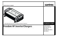
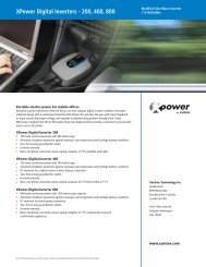
Materials List<br />
FREEDOM <strong>SW</strong> <strong>3000</strong><br />
X anbus I n ter fa ce<br />
In ver ter<br />
Res et Enable Inv e rter A C/<br />
The <strong>Freedom</strong> <strong>SW</strong> <strong>3000</strong> ships with the following items:<br />
• one <strong>Freedom</strong> <strong>SW</strong> <strong>3000</strong> unit,<br />
• owner’s and installation guides,<br />
• Battery Temperature Sensor (BTS),<br />
• <strong>Freedom</strong> <strong>SW</strong> remote panel with 25-foot communications cable,<br />
• DC terminal covers (one red, one black) with two sets of screws, and<br />
• two sets of nuts and washers for the DC terminals.<br />
On C ha rge Fault<br />
FREEDOM<strong>SW</strong> <strong>3000</strong><br />
REM BTS<br />
<strong>Freedom</strong> <strong>SW</strong> <strong>3000</strong><br />
Installation and<br />
Owner’s Guides<br />
NOTE: If any of the items are missing, contact <strong>Xantrex</strong> or any authorized<br />
<strong>Xantrex</strong> dealer for replacement. See “Contact Information” on page i.<br />
Remote Panel with<br />
communications cable<br />
BTS<br />
IMPORTANT: Keep the carton and packing material in case you need to<br />
return the <strong>Freedom</strong> <strong>SW</strong> <strong>3000</strong> for servicing.<br />
DC terminal covers<br />
with screws<br />
Figure 1 Materials List<br />
nuts and washers<br />
975-0545-01-01 1
Introduction<br />
About the <strong>Freedom</strong> <strong>SW</strong> <strong>3000</strong><br />
<strong>Inverter</strong>/<strong>Charger</strong><br />
The <strong>Freedom</strong> <strong>SW</strong> <strong>3000</strong> is a convenient combination of an inverter,<br />
multistage battery charger, and transfer switch in one electronic device.<br />
• As an inverter, the <strong>Freedom</strong> <strong>SW</strong> <strong>3000</strong> provides true sine wave power<br />
for your microwave, entertainment system, computer, and other loads.<br />
This power is identical to the AC source provided from the utility grid<br />
(power company).<br />
• Some of the benefits of true sine wave power include consistent<br />
cooking in your microwave, handling of sensitive loads such as your<br />
TV set, dimmer switches, and appliances with speed controls.<br />
• As a 150 amp power-factor corrected charger, the <strong>Freedom</strong> <strong>SW</strong> <strong>3000</strong><br />
quickly and efficiently recharges your batteries.<br />
• Unique split phase design transfers up to 7.2 kW of incoming qualified<br />
AC power.<br />
Premium Power and Ease of Use<br />
For managing your onboard power system, the <strong>Freedom</strong> <strong>SW</strong> <strong>3000</strong> provides<br />
superior features and rugged durability combined with ease of use. The<br />
<strong>Freedom</strong> <strong>SW</strong> <strong>3000</strong>:<br />
• Produces 120 volts AC at up to <strong>3000</strong> watts continuous with a 6000-<br />
watt surge for ten seconds,<br />
• Provides three-stage charging with 150 amps of output and charge<br />
formulas for flooded, gel, and AGM deep cycle batteries plus<br />
equalization for flooded batteries,<br />
• Powers sensitive entertainment electronics using true sine wave power,<br />
• Allows split phase input transfers of two legs of 30 amps to make full<br />
use of the available AC power,<br />
• Has easy-to-read indicator lights on the front panel,<br />
• Has automatic cooling fans, and<br />
• Provides power sharing which reduces the charging current to prevent<br />
unnecessary tripping of an AC input breaker.<br />
2 <strong>Freedom</strong> <strong>SW</strong> <strong>3000</strong> Owner’s Guide
How the <strong>Freedom</strong> <strong>SW</strong> <strong>3000</strong> <strong>Inverter</strong>/<strong>Charger</strong><br />
Works<br />
The <strong>Freedom</strong> <strong>SW</strong> <strong>3000</strong> is designed to:<br />
• invert,<br />
• charge, and<br />
• accept both split phase and dual input.<br />
With AC input available from the utility grid or a generator, power is passed<br />
through the <strong>Freedom</strong> <strong>SW</strong> <strong>3000</strong> <strong>Inverter</strong>/<strong>Charger</strong> to operate connected AC<br />
loads. The remaining AC power not used by loads is converted to DC<br />
power and used to charge batteries.<br />
If AC input power becomes disconnected, fails, or falls out of specification<br />
and is no longer qualified as good AC, a quick transfer takes place and the<br />
<strong>Freedom</strong> <strong>SW</strong> <strong>3000</strong> begins converting DC power from the batteries into AC<br />
power, to continue to supply power to the AC loads.<br />
Inverting<br />
The <strong>Freedom</strong> <strong>SW</strong> <strong>3000</strong>’s inverting function produces 120 volts AC from<br />
your batteries at <strong>3000</strong> watts continuous with 6000 watts of surge power to<br />
start loads like pumps and refrigerators.<br />
Charging<br />
Introduction<br />
The <strong>Freedom</strong> <strong>SW</strong> <strong>3000</strong>’s charging function:<br />
• produces 150 amps to charge your batteries, and<br />
• equalizes flooded, lead acid batteries.<br />
Built-in Charge Formulas For the unit to perform at the highest level,<br />
the batteries must be charged correctly. The <strong>Freedom</strong> <strong>SW</strong> <strong>3000</strong> has<br />
optimized algorithms for flooded, gel, and AGM batteries.<br />
Battery Temperature Sensor Since battery temperature is a key factor<br />
in correct charging, the charging formula must be adjusted (automatically<br />
and in real time) according to the actual battery temperature to ensure that<br />
batteries are fully charged, but not overcharged. For this reason, <strong>Xantrex</strong>®<br />
has included a battery temperature sensor with your <strong>Freedom</strong> <strong>SW</strong> <strong>3000</strong> and<br />
has temperature compensated the charge formula.<br />
Manual Equalization Over a period of time, the cells in a flooded<br />
battery can develop uneven chemical states. This can result in a weak<br />
(undercharged) cell which, in turn, can reduce the overall capacity of the<br />
battery. To improve the life and performance of a non-sealed, flooded<br />
battery, the <strong>Freedom</strong> <strong>SW</strong> <strong>3000</strong>’s multi-stage charging cycle includes a<br />
manual equalize mode that can be used, if recommended by the battery<br />
manufacturer.<br />
Dead Battery Charging Another feature that the <strong>Freedom</strong> <strong>SW</strong> <strong>3000</strong><br />
includes is dead battery charging. The <strong>Freedom</strong> <strong>SW</strong> <strong>3000</strong>—unlike many<br />
chargers—has the ability to recharge batteries even if the battery voltage is<br />
very low, i.e., as low as 5 volts.<br />
975-0545-01-01 3
Introduction<br />
Load Management The <strong>Freedom</strong> <strong>SW</strong> <strong>3000</strong> has a built-in transfer relay<br />
that connects your inverter output or AC input from the utility grid or<br />
generator to your loads. Because the usual AC power sources such as<br />
campground outlets or small generators often have limited current<br />
availability, having the capability to manage your AC loads is extremely<br />
valuable. The <strong>Freedom</strong> <strong>SW</strong> <strong>3000</strong> provides a number of features to facilitate<br />
this:<br />
• The charger is power factor corrected to use AC current as efficiently<br />
as possible and only requires 22 amps to provide rated charger output.<br />
Minimizing the AC current used by the charger means more current is<br />
available for your AC loads.<br />
• <strong>Freedom</strong> <strong>SW</strong> <strong>3000</strong> has a power share feature which prioritizes your<br />
AC loads by reducing the charge current and maintaining the total<br />
input current to less than your breaker setting or the breaker setting.<br />
• Occasionally, AC input sources have low voltage. To avoid loading<br />
these weak sources any further, the charger automatically reduces its<br />
AC current draw as the AC voltage approaches the minimum<br />
acceptable level.<br />
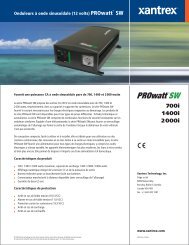
Xanbus ® System<br />
The Xanbus system includes the <strong>Freedom</strong> <strong>SW</strong> <strong>3000</strong> and other Xanbusenabled<br />
devices. The <strong>Freedom</strong> <strong>SW</strong> <strong>3000</strong> is the device in a Xanbus system<br />
that typically provides network power—500 mA at 12 volts DC. All of the<br />
Xanbus-enabled devices, such as the <strong>Freedom</strong> <strong>SW</strong> <strong>3000</strong>, the System<br />
Control Panel (SCP), and the Automatic Generator Starter (AGS) are able<br />
to communicate their settings and activity to each other. See Figure 1.<br />
AC In<br />
AC Out<br />
Figure 1 Typical Xanbus System Diagram<br />
4 <strong>Freedom</strong> <strong>SW</strong> <strong>3000</strong> Owner’s Guide
Comprehensive Electronic Protection<br />
Introduction<br />
The Xanbus-enabled designation means that this product works on a<br />
Xanbus network. Xanbus-enabled products are:<br />
• Easy to use. The Xanbus network simplifies operation and automates<br />
routine tasks.<br />
• Reliable. Software control eliminates analog signalling errors.<br />
• Accurate. Digital information is less susceptible to interference and<br />
line loss.<br />
• Upgradeable. Software upgrades mean your purchase will remain up<br />
to date.<br />
For detailed instructions and a complete list of Xanbus-enabled devices,<br />
visit www.xantrex.com<br />
<strong>Freedom</strong> <strong>SW</strong> <strong>3000</strong> is approved to meet a number of safety standards<br />
including UL 458 and CSA C22.2 No. 107.1. See “Regulatory Approvals”<br />
on page 63 for more information.<br />
<strong>Freedom</strong> <strong>SW</strong> <strong>3000</strong> is equipped with numerous protection features to ensure<br />
safe operation.<br />
Protection feature<br />
Battery over-voltage<br />
protection<br />
Battery under-voltage<br />
protection<br />
Over-temperature<br />
protection<br />
Automatic overload<br />
protection<br />
Short circuit protection<br />
This feature…<br />
Keeps the battery voltage from getting too<br />
high in charge mode. Shuts the inverter off in<br />
invert mode.<br />
Prevents inverter from discharging your<br />
batteries too low. The inverter doesn’t run if<br />
battery voltage is too low.<br />
Protects the unit from overheating by either<br />
derating (charge mode) or by shutting down<br />
(invert mode). See “Invert Power Derating<br />
versus Ambient Temperature” on page 64.<br />
Protects the unit from excessive loads. The<br />
unit will provide 6000 watts (twice the rated<br />
load) for up to ten seconds, and then protect<br />
itself by shutting down. See “<strong>Inverter</strong><br />
Specifications” on page 61 for more<br />
information.<br />
Protects the unit by shutting it down.<br />
975-0545-01-01 5
30 3614<br />
UL 458<br />
CSA 107.1-01<br />
FGA<br />
Number<br />
<strong>Freedom</strong> <strong>SW</strong> <strong>3000</strong> <strong>Inverter</strong>/<strong>Charger</strong> Features<br />
This section describes the different parts of the <strong>Freedom</strong> <strong>SW</strong> <strong>3000</strong>.<br />
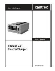
Front and Side Panels<br />
Front Panel<br />
Controls and<br />
Status LEDs<br />
AC<br />
Compartment<br />
Side<br />
<strong>3000</strong>W SINEWAVE INVERTER/CHARGER<br />
FREEDOM <strong>SW</strong> <strong>3000</strong><br />
Model<br />
Number<br />
F<strong>SW</strong><strong>3000</strong><br />
815-<strong>3000</strong><br />
<strong>Inverter</strong> Mode:<br />
Nominal DC Operating Voltage: 12 Vdc<br />
Nominal AC Output Voltage: 120 Vac , 1Ø<br />
Nominal AC Output Frequency: 60 Hz<br />
Max. Continuous AC Output Cu rent: 25 A<br />
Max. Operating DC Input Cu rent: 320 A<br />
Max. Continuous AC Output at Nominal DC<br />
Input: <strong>3000</strong> VA at 25°C<br />
Max. Output Surge Power (5 s duration): 6000 VA<br />
Max. DC Input Voltage: 16 Vdc<br />
Max. Ambient Temperature: 50°C<br />
Nominal AC Input Voltage: 120 Vac , 60 Hz, 1Ø<br />
Power Factor: > 0.95<br />
Charging DC Output Voltage Range: 5.0 - 16.0 Vdc<br />
Max. Continuous Ba tery <strong>Charger</strong> DC Cu rent at<br />
Nominal AC Input: 150 A<br />
Max. AC Input Cu rent: 30 A per line Split Phase,<br />
30 A per line Dual<br />
<strong>Charger</strong> Mode:<br />
INSTALLATION REQUIREMENTS:<br />
Moun this inverter/charger only in the orientations<br />
Serial Number<br />
FREEDOM <strong>SW</strong> <strong>3000</strong><br />
Xanbus Interface<br />
<strong>Inverter</strong><br />
Reset Enable <strong>Inverter</strong> AC/<br />
On Charge Fault<br />
FREEDOM <strong>SW</strong> <strong>3000</strong><br />
Xanbus Interface<br />
FREEDOM <strong>SW</strong> <strong>3000</strong><br />
<strong>Inverter</strong><br />
Reset Enable <strong>Inverter</strong> AC/<br />
specified in the insta lation guide provided.<br />
On Charge Fault<br />
CAUTION: To reduce the risk o fire, do not<br />
Designed in Canada<br />
A sembled in China<br />
cover or obstruct ventilation openings. Do not mount<br />
in a zero-clearance compartment. Overheating may<br />
result. Do not expose to rain or spray.<br />
FREEDOM <strong>SW</strong> <strong>3000</strong><br />
WARNING: Shock hazard. Do not open. No<br />
user serviceable parts. Energized from both AC and<br />
DC sources. Disconnect a l sources before servicing.<br />
Use only ground-fault circuit inte rupters (GFCI)<br />
specified in the insta lation guide supplied. Other<br />
Date of Manufacture<br />
types may fail to operate properly when connected to<br />
this equipment. Refer to manual. Charge only<br />
lead-acid ba teries. Other ba tery types may burst<br />
causing personal injury and damage.<br />
DANGER: To reduce the risk of explosion, do not<br />
insta l in an area in which ignition-protected<br />
euipment is required.<br />
Cooling Fans<br />
DC Terminal Side<br />
and Ground Terminal Stud<br />
Figure 2 <strong>Freedom</strong> <strong>SW</strong> <strong>3000</strong> Front and Side Panels<br />
6 <strong>Freedom</strong> <strong>SW</strong> <strong>3000</strong> Owner’s Guide
UL 458<br />
Front and Side Panels<br />
Before you begin to operate the <strong>Freedom</strong> <strong>SW</strong> <strong>3000</strong>, review the front panel<br />
features shown in Figure 3 and described in the next table. A detailed view<br />
of the lights and buttons on the front panel is shown in Figure 4 and<br />
described in the table next to it.<br />
3<br />
FREEDOM <strong>SW</strong> <strong>3000</strong><br />
<strong>3000</strong>W SINEWAVE INVERTER/CHARGER<br />
30 3614<br />
CSA 107.1-01<br />
Model<br />
Number<br />
FGA<br />
Number<br />
F<strong>SW</strong><strong>3000</strong><br />
815-<strong>3000</strong><br />
<strong>Inverter</strong> Mode:<br />
Nominal DC Operating Voltage: 12 Vdc<br />
Nominal AC Output Voltage: 120 Vac , 1Ø<br />
Nominal AC Output Frequency: 60 Hz<br />
Max. Continuous AC Output Cu rent: 25 A<br />
Max. Operating DC Input Cu rent: 320 A<br />
Max. Continuous AC Output at Nominal DC<br />
Input: <strong>3000</strong> VA at 25°C<br />
Max. Output Surge Power (5 s duration): 6000 VA<br />
Max. DC Input Voltage: 16 Vdc<br />
Max. Ambient Temperature: 50°C<br />
Nominal AC Input Voltage: 120 Vac , 60 Hz, 1Ø<br />
Power Factor: > 0.95<br />
Charging DC Output Voltage Range: 5.0 - 16.0 Vdc<br />
Max. Continuous Ba tery <strong>Charger</strong> DC Cu rent at<br />
Nominal AC Input: 150 A<br />
Max. AC Input Cu rent: 30 A per line Split Phase,<br />
30 A per line Dual<br />
<strong>Charger</strong> Mode:<br />
Serial Number<br />
FREEDOM <strong>SW</strong> <strong>3000</strong><br />
Xanbus Interface<br />
<strong>Inverter</strong><br />
Reset Enable <strong>Inverter</strong> AC/<br />
On Charge Fault<br />
FREEDOM <strong>SW</strong> <strong>3000</strong><br />
1<br />
Item<br />
Description<br />
<strong>Freedom</strong> <strong>SW</strong> <strong>3000</strong> <strong>Inverter</strong>/<strong>Charger</strong> Features<br />
1 Front Panel contains the Xanbus interface ports for<br />
connecting Xanbus-enabled devices, the <strong>Inverter</strong> Enable<br />
and Reset buttons, as well as various LED status lights.<br />
See Figure 4.<br />
2 Mounting holes are used for mounting the unit. A total of<br />
eight holes are provided on the unit.<br />
3 Two variable-speed cooling fans are used to cool the<br />
unit. Fan speed control is based on internal temperature of<br />
critical components. The two exhaust fans control airflow<br />
though the transformer and power compartments of the<br />
unit. Ensure at least six inches of clearance for proper<br />
ventilation.<br />
INSTALLATION REQUIREMENTS:<br />
Moun this inverter/charger only in the orientations<br />
specified in the insta lation guide provided.<br />
CAUTION: To reduce the risk o fire, do not<br />
Designed in Canada<br />
A sembled in China<br />
cover or obstruct ventilation openings. Do not mount<br />
in a zero-clearance compartment. Overheating may<br />
result. Do not expose to rain or spray.<br />
WARNING: Shock hazard. Do not open. No<br />
user serviceable parts. Energized from both AC and<br />
DC sources. Disconnect a l sources before servicing.<br />
Use only ground-fault circuit inte rupters (GFCI)<br />
specified in the insta lation guide supplied. Other<br />
Date of Manufacture<br />
types may fail to operate properly when connected to<br />
this equipment. Refer to manual. Charge only<br />
lead-acid ba teries. Other ba tery types may burst<br />
causing personal injury and damage.<br />
DANGER: To reduce the risk of explosion, do not<br />
insta l in an area in which ignition-protected<br />
euipment is required.<br />
2<br />
Figure 3 Isometric View of the Front Panel and Fans<br />
975-0545-01-01 7
<strong>Freedom</strong> <strong>SW</strong> <strong>3000</strong> <strong>Inverter</strong>/<strong>Charger</strong> Features<br />
1<br />
FREEDOM <strong>SW</strong> <strong>3000</strong><br />
Xanbus Interface<br />
<strong>Inverter</strong><br />
Reset Enable <strong>Inverter</strong> AC/<br />
On Charge Fault<br />
FREEDOM <strong>SW</strong> <strong>3000</strong><br />
8<br />
Xanbus Interface<br />
7<br />
6<br />
5<br />
4<br />
3<br />
<strong>Inverter</strong><br />
Reset Enable <strong>Inverter</strong> AC/<br />
On Charge Fault<br />
2<br />
Item Description<br />
1 DC terminals. See “AC and DC Side Panels” on page 9<br />
for more information.<br />
2 AC wiring compartment access panel with<br />
compartment cover on. See “AC and DC Side Panels” on<br />
page 9 for more information.<br />
3 Fault light illuminates if a fault condition occurs.<br />
4 AC/Charge light illuminates when the <strong>Freedom</strong> <strong>SW</strong><br />
<strong>3000</strong> is in charge mode and is producing DC output to<br />
charge your batteries. AC/Charge also illuminates when<br />
you are connected to an AC source like the utility grid or<br />
a generator and the AC is qualified.<br />
5 <strong>Inverter</strong> On indicates the unit is in invert mode.<br />
NOTE: If AC is present and invert mode is enabled, this<br />
light remains illuminated even though AC power is being<br />
passed through.<br />
6 <strong>Inverter</strong> Enable button is used to switch the inverter on<br />
and off.<br />
7 Reset button is used to clear any active faults if pressed<br />
momentarily. If held down for more than three seconds,<br />
the unit will reset (reboot) itself.<br />
8 Xanbus Interface ports are used to connect Xanbusenabled<br />
devices including the optional SCP and AGS.<br />
FREEDOM <strong>SW</strong> <strong>3000</strong><br />
Figure 4 Isometric View of the Front Panel and AC/DC Side Panel<br />
8 <strong>Freedom</strong> <strong>SW</strong> <strong>3000</strong> Owner’s Guide
AC and DC Side Panels<br />
The DC side of the <strong>Freedom</strong> <strong>SW</strong> <strong>3000</strong> has the equipment ground lug, the<br />
positive (+) battery terminal, and the negative (–) battery terminal plus the<br />
remote network com port and battery temperature sensor com port.<br />
1<br />
REM<br />
2<br />
BTS<br />
Figure 5 AC and DC Side Panel<br />
3<br />
WARNING: INCORRECT BATTERY POLARITY WILL CAUSE DAMAGE TO UNIT.<br />
4 9 8<br />
INVERTER<br />
AC OUTPUT<br />
Wiring box cover must be in place during<br />
use to reduce risk of injury to persons<br />
7 6<br />
AC INPUT<br />
LINE 1<br />
AC INPUT<br />
LINE 2<br />
5<br />
AC<br />
IN<br />
AC<br />
OUT<br />
AC GROUNDS<br />
(BEHIND COVER)<br />
<strong>Freedom</strong> <strong>SW</strong> <strong>3000</strong> <strong>Inverter</strong>/<strong>Charger</strong> Features<br />
975-0545-01-01 9<br />
Item<br />
Description<br />
1 Remote (REM) jack provides connection for the<br />
<strong>Freedom</strong> <strong>Sine</strong> <strong>Wave</strong> remote panel (supplied).<br />
2 Battery temperature sensor (BTS) jack provides<br />
connection for the battery temperature sensor (supplied).<br />
3 Negative (–) DC terminal connects to the negative<br />
battery cable (black). Install a DC terminal cover<br />
(supplied) over the terminal.<br />
4 Positive (+) DC terminal connects to the positive battery<br />
cable (red). Install a DC terminal cover (supplied) over<br />
the terminal.<br />
5 AC Input 1, AC Input 2, and <strong>Inverter</strong> AC Output<br />
circuit breaker switches allow you to reset the circuit<br />
breakers when they trip.<br />
6 AC knockouts provide access for AC cables (both input<br />
and output wiring). Detach the knockout covers and<br />
install the strain-relief clamps (supplied).<br />
7 AC Output terminal block is a screw-type terminal<br />
block for attaching AC output wires. Each slot is labeled<br />
N1 for Neutral 1, L1 and L2 for Lines 1 and 2, and N2 for<br />
Neutral 2.<br />
8 AC Input terminal block is a screw-type terminal block<br />
for attaching AC input wires. Each slot is labeled<br />
N for Neutral and L1 and L2 for Lines 1 and 2.<br />
9 Chassis ground lug connects the chassis of the F<strong>SW</strong><strong>3000</strong><br />
to your system’s chassis grounding point.<br />
Not<br />
shown<br />
All Ground terminals are along the tab at the bottom of<br />
the opening to the AC wiring compartment access panel.
<strong>Freedom</strong> <strong>SW</strong> <strong>3000</strong> <strong>Inverter</strong>/<strong>Charger</strong> Features<br />
Supplied Accessories<br />
Figure 6 Supplied Accessories<br />
4<br />
NOTE: If any of the supplied accessories are missing, contact <strong>Xantrex</strong> or any<br />
authorized <strong>Xantrex</strong> dealer for replacement. See “Contact Information” on<br />
page i.<br />
3<br />
1<br />
2<br />
Item<br />
Description<br />
1 Two DC terminal covers are supplied to prevent<br />
accidental contact with the DC cable connectors after<br />
installation. The red cover is for the positive cabling<br />
terminal, and the black cover is for the negative cabling<br />
terminal.<br />
2 BTS, the Battery Temperature Sensor consists of:<br />
• Connector plugs into the BTS jack on the <strong>Freedom</strong><br />
<strong>SW</strong> <strong>3000</strong>.<br />
• Sensor cable is 25 feet (7.6 meters).<br />
• Sensor can be mounted on the side of the battery case<br />
or on the negative battery terminal.<br />
NOTE: The BTS continuously measures the temperature<br />
of the battery and adjusts the charger output for a more<br />
accurate, temperature-compensated charge.<br />
3 <strong>Freedom</strong> <strong>Sine</strong> <strong>Wave</strong> remote panel (with 25-ft<br />
communications cable) is functionally similar to the<br />
<strong>Inverter</strong> Enable button on the unit’s front panel. It enables<br />
and disables the <strong>Freedom</strong> <strong>SW</strong> <strong>3000</strong>’s inverter mode<br />
remotely. Connects to the REM jack on the <strong>Freedom</strong> <strong>SW</strong><br />
<strong>3000</strong>.<br />
4 Two sets of nuts and washers are used to secure DC<br />
cable ends to the DC terminals.<br />
10 <strong>Freedom</strong> <strong>SW</strong> <strong>3000</strong> Owner’s Guide
Optional System Accessories and Network Components<br />
<strong>Freedom</strong> <strong>SW</strong> <strong>3000</strong> <strong>Inverter</strong>/<strong>Charger</strong> Features<br />
System accessories can be used with the <strong>Freedom</strong> <strong>SW</strong> <strong>3000</strong> in a Xanbus<br />
system. The SCP provides configuration and monitoring capability for<br />
Xanbus-enabled devices such as the <strong>Freedom</strong> <strong>SW</strong> <strong>3000</strong>. AGS automatically<br />
starts and stops your generator.<br />
Table 1 provides the part numbers for the system accessories.<br />
These optional accessories and network components are available from any<br />
authorized <strong>Xantrex</strong> dealer or at www.xantrex.com. Detailed information<br />
on planning and installing your network is available in the Xanbus System<br />
Installation Guide. This guide is available for downloading at<br />
www.xantrex.com<br />
Table 1 System Accessories<br />
Accessory<br />
Part number<br />
SCP 809-0910<br />
AGS 809-0915<br />
Consult with your local system designer to determine what network<br />
components will be needed for your specific installation. Table 2 provides a<br />
list of network components and part numbers. Pre-made cables are<br />
available in standard lengths ranging from 3 feet to 75 feet.<br />
Table 2 Network Components and Part Numbers<br />
Network Component<br />
Part Number<br />
Network cable 3 ft. (0.9 m) 809-0935<br />
Network cable 25 feet (7.6 m) 809-0940<br />
Network cable 75 feet (22.9 m) 809-0942<br />
975-0545-01-01 11
Operating The <strong>Freedom</strong> <strong>SW</strong> <strong>3000</strong><br />
This section contains detailed information and procedures for using your<br />
<strong>Freedom</strong> <strong>SW</strong> <strong>3000</strong>.<br />
If you’re using the SCP to operate or monitor the status of the unit, also<br />
refer to the System Control Panel Owner’s Guide.<br />
LIMITATIONS ON USE<br />
• Do not use in connection with life support systems or other medical<br />
equipment or devices.<br />
• Do not use in ambulances or other life-saving emergency vehicles.<br />
Failure to follow these instructions can result in death or serious<br />
injury.<br />
Operating the <strong>Freedom</strong> <strong>SW</strong> <strong>3000</strong> with the<br />
Optional System Control Panel (SCP)<br />
The SCP provides operating, configuration, and monitoring capability for<br />
your Xanbus system.<br />
The System Control Panel:<br />
• Monitors activity throughout your onboard power system.<br />
• Displays the latest information about your inverter/charger, battery<br />
charge level, battery charge output, and generator start and stop<br />
activity.<br />
• Displays the settings for each Xanbus-enabled device in the system.<br />
• Enables you to adjust the settings for each Xanbus-enabled device in<br />
the system.<br />
• Preserves all of its settings if system power is interrupted. After power<br />
is restored, you don’t have to reconfigure the SCP or any of the<br />
Xanbus-enabled devices connected to it.<br />
This section provides information on operating the <strong>Freedom</strong> <strong>SW</strong> <strong>3000</strong> with<br />
the System Control Panel. Please refer to the System Control Panel<br />
Owner’s Guide for complete information on using the System Control<br />
Panel.<br />
12 <strong>Freedom</strong> <strong>SW</strong> <strong>3000</strong> Owner’s Guide
Using the SCP<br />
Operating The <strong>Freedom</strong> <strong>SW</strong> <strong>3000</strong><br />
As shown in Figure 7, the SCP has these important features :<br />
Display screen System information is shown on the display screen with<br />
an adjustable backlight.<br />
Indicator lights Four indicator lights on the front panel indicate the<br />
operating status of the Xanbus system.<br />
Push buttons Four push buttons allow you to select device menus and<br />
change or display settings. The red System button toggles the SCP and<br />
Xanbus-enabled devices between Operating mode and Power Save mode, if<br />
held down for more than three seconds. The button can also be used to clear<br />
any active faults or warnings by momentarily depressing the button.<br />
For more information on the different system modes, see “Operating in<br />
Invert Mode” on page 16.<br />
1 2 3 4<br />
5<br />
6<br />
10 9 8 7<br />
Figure 7 System Control Panel (SCP)<br />
975-0545-01-01 13
Operating The <strong>Freedom</strong> <strong>SW</strong> <strong>3000</strong><br />
Item<br />
Description<br />
1 AC In/Charge light indicates that qualified AC is present<br />
at the input of an inverter/charger. When the <strong>Freedom</strong> <strong>SW</strong><br />
<strong>3000</strong> is connected to a qualified AC source like the utility<br />
grid or a generator, this light on the SCP illuminates.<br />
2 <strong>Inverter</strong> On light illuminates when the <strong>Freedom</strong> <strong>SW</strong><br />
<strong>3000</strong> is enabled (turned on).<br />
3 Low Battery light illuminates when the battery voltage<br />
on the <strong>Freedom</strong> <strong>SW</strong> <strong>3000</strong> is low.<br />
4 Fault light indicates a condition that requires user<br />
attention and intervention. The Fault light illuminates<br />
when any Xanbus-enabled device connected to the<br />
network is in fault. See “Faults and Warnings” on page 21<br />
for the definitions of a fault and warning.<br />
5 System button is used to clear active faults on the system<br />
if pressed momentarily. It also toggles all Xanbus-enabled<br />
devices on the system between Operating mode and<br />
Power Save mode when held down for more than five<br />
seconds. See “Operating in Invert Mode” on page 16.<br />
6 Screen displays menus, settings, and system information.<br />
7 Exit button:<br />
• Cancels selection of a menu item.<br />
• Returns you to the previous screen.<br />
Item<br />
Description<br />
8 Down arrow button:<br />
• Scrolls down one line of text.<br />
• Decreases a selected value.<br />
9 Up arrow button:<br />
• Scrolls up one line of text.<br />
• Increases a selected value.<br />
10 Enter button:<br />
• Confirms selection of a menu item.<br />
• Moves you to the next screen.<br />
On Start Up<br />
When the <strong>Freedom</strong> <strong>SW</strong> <strong>3000</strong> is powered up or has been reset, all of the<br />
front panel lights illuminate and remain on for a minimum of five seconds.<br />
After five seconds, the lights remain illuminated until the front panel has<br />
status information for all the lights.<br />
The <strong>Freedom</strong> <strong>SW</strong> <strong>3000</strong> inverter is disabled every time the <strong>Freedom</strong> <strong>SW</strong><br />
<strong>3000</strong> is powered up. After power up, the <strong>Inverter</strong> Enable button or the<br />
System Control Panel can be used to enable or disable the inverter. The<br />
power up behavior of the <strong>Freedom</strong> <strong>SW</strong> <strong>3000</strong> charger is determined by the<br />
'Force Charge' setting (see page 40).<br />
When a function is enabled, it is allowed to occur but other conditions may<br />
have to be met before the function is activated or turned on. For example,<br />
the charger function on the <strong>Freedom</strong> <strong>SW</strong> <strong>3000</strong> may be enabled, but it will<br />
not charge unless qualified AC power is present.<br />
14 <strong>Freedom</strong> <strong>SW</strong> <strong>3000</strong> Owner’s Guide
System Start-up Check<br />
IMPORTANT: Review the “Important Safety Instructions” on page iv<br />
before operating the inverter/charger.<br />
To test inverting and charging from the <strong>Freedom</strong> <strong>SW</strong> <strong>3000</strong> front panel:<br />
1. Disconnect AC power from inverter input by opening the breaker or<br />
disconnect. Press the <strong>Inverter</strong> Enable button on the <strong>Freedom</strong> <strong>SW</strong> <strong>3000</strong>.<br />
The <strong>Inverter</strong> On light illuminates.<br />
2. Place a load on the inverter. For example, plug a 100 watt light bulb<br />
into an outlet that the inverter is powering and make sure it works. The<br />
inverter should run the load using battery power.<br />
3. To test the charger, reconnect the AC input power to allow AC to the<br />
AC input. The AC/<strong>Charger</strong> On light should illuminate after a brief<br />
delay. Any AC loads previously powered by the inverter will also<br />
work at this time.<br />
4. Remove the AC input power. The inverter/charger should transfer to<br />
invert mode immediately. (The transfer relay will make a clicking<br />
sound and the <strong>Inverter</strong> On light will illuminate.) Loads should<br />
continue to operate uninterrupted.<br />
If any part of this test fails, determine the cause before using the unit.<br />
Consult the “Troubleshooting” chapter starting on page 45.<br />
Operating The <strong>Freedom</strong> <strong>SW</strong> <strong>3000</strong><br />
Viewing the Firmware Revision Number<br />
You may need to view the firmware revision number of the <strong>Freedom</strong> <strong>SW</strong><br />
<strong>3000</strong> when troubleshooting the unit with authorized service personnel.<br />
To view the firmware revision number:<br />
1. On the Select Device menu, use the down arrow button to highlight<br />
System and press Enter.<br />
The System Settings menu appears.<br />
2. Press the down arrow button to highlight View Device info and press<br />
Enter.<br />
The Device Info screen appears.<br />
3. Press the down arrow button until the <strong>Freedom</strong> <strong>SW</strong> <strong>3000</strong> screen<br />
appears.<br />
The number opposite “F/W Rev.” is the firmware revision number.<br />
4. Press Exit to return to the System Settings menu.<br />
975-0545-01-01 15
Operating The <strong>Freedom</strong> <strong>SW</strong> <strong>3000</strong><br />
Operating in Invert Mode<br />
IMPORTANT: Review the “Important Safety Instructions” on page iv<br />
before operating the inverter/charger.<br />
Once the inverter/charger is installed, you can operate it in invert mode.<br />
To operate in invert mode from the front panel:<br />
1. Press the <strong>Inverter</strong> Enable button on the <strong>Freedom</strong> <strong>SW</strong> <strong>3000</strong>.<br />
2. If external AC is present, the External AC light illuminates. If AC is<br />
present and you want to operate the inverter, remove AC so the<br />
inverter turns on.<br />
◆ Once the <strong>Inverter</strong> On light is on, the <strong>Freedom</strong> <strong>SW</strong> <strong>3000</strong> inverter is<br />
ready to deliver AC power to the loads.<br />
To operate the inverter with the System Control Panel, refer to “Operating<br />
the <strong>Freedom</strong> <strong>SW</strong> <strong>3000</strong> with the Optional System Control Panel (SCP)” on<br />
page 12.<br />
IMPORTANT: If you are having problems with any of your loads, refer to<br />
“<strong>Inverter</strong> Applications” on page 54.<br />
Operating Limits for <strong>Inverter</strong> Operation<br />
Temperature The <strong>Freedom</strong> <strong>SW</strong> <strong>3000</strong> produces 120 volts AC at <strong>3000</strong><br />
watts continuously in room temperature. The <strong>Freedom</strong> <strong>SW</strong> <strong>3000</strong> can deliver<br />
this power in an ambient (surrounding) temperature up to 77 °F (25 °C). In<br />
higher ambient temperatures, if the loads draw full power for an extended<br />
period of time, the unit may shut down to protect itself against overheating.<br />
As with all inverters, the amount of continuous power that the <strong>Freedom</strong> <strong>SW</strong><br />
<strong>3000</strong> can deliver without overheating is limited by the ambient air<br />
temperature. The <strong>Freedom</strong> <strong>SW</strong> <strong>3000</strong> will operate and deliver its continuous<br />
power rating at higher temperatures, but the ambient temperature as well as<br />
the input voltage from the battery will limit the extent to which the unit can<br />
run continuously.<br />
The <strong>Freedom</strong> <strong>SW</strong> <strong>3000</strong> has 6000-watt surge for ten seconds. Operating the<br />
inverter/charger in conditions outside of power and temperature limits,<br />
however, will result in thermal shutdown and/or significantly decreased<br />
performance. In addition, operation in this range is outside the ratings<br />
covered by the regulatory approvals of the product. See “Invert Power<br />
Derating versus Ambient Temperature” on page 64.<br />
Difficulty on starting loads The inverter/charger should be able to<br />
operate all AC loads rated at or below its power rating. Some high<br />
horsepower induction motors used in pumps and other motor-operated<br />
equipment require very high surge currents to start, and the inverter/charger<br />
may have difficulty starting these loads. See “<strong>Inverter</strong> Applications” on<br />
page 54.<br />
If you have problems starting certain loads, ensure that:<br />
• the battery connections are tight and clean,<br />
• the DC cabling is no longer than the recommended length. Refer to the<br />
F<strong>SW</strong><strong>3000</strong> <strong>Sine</strong> <strong>Wave</strong> <strong>Inverter</strong>/<strong>Charger</strong> Installation Guide for this<br />
information,<br />
• the AC wiring is of recommended size. Refer to the F<strong>SW</strong><strong>3000</strong> <strong>Sine</strong><br />
<strong>Wave</strong> <strong>Inverter</strong>/<strong>Charger</strong> Installation Guide for this information, and<br />
• the battery is of sufficient capacity and is fully charged.<br />
16 <strong>Freedom</strong> <strong>SW</strong> <strong>3000</strong> Owner’s Guide
Operating in <strong>Charger</strong> Mode<br />
EXPOSURE TO CHEMICALS AND GASES HAZARD<br />
• Make sure the area around the battery is well ventilated.<br />
• Make sure the voltage of the batteries matches the output voltage of<br />
the inverter/charger.<br />
Failure to follow these instructions can result in death or serious<br />
injury.<br />
NOTES:<br />
• Study and follow all of the battery manufacturer's specific precautions,<br />
such as removing or not removing cell caps while charging, whether<br />
equalization is acceptable for your battery, and recommended rates of<br />
charge.<br />
• For flooded non-sealed batteries, add distilled water in each cell until<br />
battery acid reaches the level specified by the battery manufacturer.<br />
This helps to purge excessive gas from cells. Do not overfill. For a<br />
battery without removable cell caps, carefully follow manufacturer's<br />
instructions.<br />
To operate the <strong>Freedom</strong> <strong>SW</strong> <strong>3000</strong> in charger mode from the front<br />
panel:<br />
1. Connect AC input power.<br />
The charger automatically starts up when qualified AC power is<br />
connected if the charger is enabled, or the charger is disabled but the<br />
Force Charge enable override is On. See “Force Charge” on page 23.<br />
Operating The <strong>Freedom</strong> <strong>SW</strong> <strong>3000</strong><br />
• The batteries are charged according to the two-stage or three-stage<br />
formula you have selected on the SCP. See “Battery Charging<br />
Reference” on page 55 for more information on two-stage or threestage<br />
charging.<br />
• You can interrupt the charge cycle any time you desire by disabling the<br />
charger from the SCP.<br />
• To maintain optimal performance in flooded batteries, an occasional<br />
equalize cycle may be required. See “Operating in Equalization Mode”<br />
on page 18.<br />
• While the batteries are being charged, you can monitor which stage<br />
they are in from the front panel of the <strong>Freedom</strong> <strong>SW</strong> <strong>3000</strong> or from the<br />
SCP.<br />
2. To operate the charger with the SCP, refer to “Configuration” on page<br />
25.<br />
<strong>Charger</strong> Operation with Battery Temperature<br />
Sensor (BTS)<br />
Since battery temperature is a key factor in correct charging, the charging<br />
formula must be adjusted (automatically and in real time) according to the<br />
actual battery temperature to ensure that batteries are fully charged, but not<br />
overcharged. For this reason, <strong>Xantrex</strong> has included a BTS (see Figure 6)<br />
with your <strong>Freedom</strong> <strong>SW</strong> <strong>3000</strong> <strong>Inverter</strong>/<strong>Charger</strong> and has temperature<br />
compensated the charge formula.<br />
The BTS continuously measures the temperature of the battery and adjusts<br />
charger output for a more accurate, temperature-compensated charge.<br />
975-0545-01-01 17
Operating The <strong>Freedom</strong> <strong>SW</strong> <strong>3000</strong><br />
When batteries are cold, their chemical reaction is sluggish, meaning they<br />
don’t absorb charge as easily. Thus a charge level optimized for room<br />
temperature will not charge the batteries sufficiently if they are cold. The<br />
charger must compensate by increasing its voltage to achieve the<br />
compensated equivalent of a room temperature charge. If the batteries are<br />
hot, the chemical reaction is hyperactive and they absorb energy too easily;<br />
thus a standard room-temperature charge would tend to overcharge a hot<br />
battery. Therefore, the charger compensates by reducing its voltage.<br />
The BTS automatically, and in real time, makes adjustments to the<br />
charger’s voltage setpoints to properly charge your batteries. The actual<br />
charge compensation formula can be found on “<strong>Charger</strong> Specifications” on<br />
page 61.<br />
IMPORTANT: It is normal to see a voltage that is different than the<br />
specified setpoint when charging if the battery case temperature is above or<br />
below 77 °F (25 °C).<br />
If a BTS is not present, the <strong>Freedom</strong> <strong>SW</strong> <strong>3000</strong> uses the hot setting, the<br />
default value, unless the setting has been adjusted during configuration.<br />
Charging may not be effective at extreme temperatures. See “<strong>Charger</strong><br />
Specifications” on page 61.<br />
Operating in Equalization Mode<br />
EXPOSURE TO CHEMICALS AND GASES HAZARD<br />
• Make sure the area around the battery is well ventilated.<br />
• Equalization generates explosive gases.<br />
Failure to follow these instructions can result in death or serious<br />
injury.<br />
RISK OF DAMAGE TO BATTERIES<br />
• Do not equalize sealed lead-acid batteries and gel batteries.<br />
• Only flooded (wet) lead-acid batteries should be equalized.<br />
• Never equalize a lead-acid battery more than necessary. Always<br />
check the electrolyte level before AND after equalization. Fill with<br />
distilled water per the battery manufacturer’s recommendation.<br />
Failure to follow these instructions can damage the unit and/or<br />
damage other equipment.<br />
NOTES:<br />
• Equalize mode is automatically disabled if you have selected “Gel” or<br />
“AGM” as the battery type.<br />
• As a general rule, do not equalize a lead-acid battery unless there are<br />
provisions to add water to it and the manufacturer recommends<br />
equalization.<br />
18 <strong>Freedom</strong> <strong>SW</strong> <strong>3000</strong> Owner’s Guide
RISK OF DAMAGE TO DC LOAD EQUIPMENT<br />
Equalization voltage may be as high as 15.8 volts DC. Disconnect<br />
sensitive loads from the battery before equalizing.<br />
Failure to follow these instructions can damage the unit and/or<br />
damage other equipment.<br />
Follow the battery manufacturer’s recommendations for equalizing your<br />
batteries. As a guide, a heavily used flooded battery may need to be<br />
equalized once a month, and a battery in light service may only need to be<br />
equalized every two to four months.<br />
Measure the specific gravity (S.G.) of each cell using a hydrometer. For<br />
fully charged lead-acid batteries, the reading should be approximately<br />
1.265. Low specific gravity after charging or a 0.25 difference from cell to<br />
cell indicates the need for equalization.<br />
Equalizing Batteries<br />
IMPORTANT: Equalization will be carried out after an absorption charge.<br />
Equalization only runs for 60 minutes and may need to be restarted if the<br />
specific gravity is still uneven.<br />
Operating The <strong>Freedom</strong> <strong>SW</strong> <strong>3000</strong><br />
To equalize your batteries:<br />
1. Turn off or disconnect all loads on the battery.<br />
The voltage applied to the battery during equalization may damage<br />
your electronic equipment. As well, equalization won’t proceed<br />
correctly if loads are drawing current from the battery.<br />
2. Check electrolyte level.<br />
Fill with distilled water if the electrolyte level is low.<br />
3. To request the equalization charge, ensure the <strong>Charger</strong> is enabled.<br />
4. On the SCP, select Equalize on the <strong>Freedom</strong> <strong>SW</strong> <strong>3000</strong> home menu.<br />
For detailed information on configuring this setting, refer to<br />
“Equalize” on page 34.<br />
5. When equalization is finished, check the battery electrolyte level. Top<br />
up as necessary with distilled water only and recheck the specific<br />
gravity as specified by the battery manufacturer.<br />
Terminating the Equalization Process<br />
The equalization process can be terminated in three ways:<br />
• user cancellation from the SCP, as shown in Figure 24 on page 36,<br />
• inverter/charger cancellation if AC is removed or the charger is<br />
disabled, or<br />
• a successful completion of the equalization process.<br />
975-0545-01-01 19
Operating The <strong>Freedom</strong> <strong>SW</strong> <strong>3000</strong><br />
Operating Limits for <strong>Charger</strong> Operation<br />
The maximum output current for the <strong>Freedom</strong> <strong>SW</strong> <strong>3000</strong> is 150 amps. You<br />
can reduce the total output if you change the “Max Chg Rate” setting on the<br />
<strong>Freedom</strong> <strong>SW</strong> <strong>3000</strong> Advanced Menu or the maximum “Power Share”setting<br />
on the <strong>Freedom</strong> <strong>SW</strong> <strong>3000</strong> Basic Menu.<br />
The charger can operate over an AC input range of 90–135 volts AC. This<br />
is the default setting and can be adjusted to 85–145 volts AC as a maximum<br />
range and to 110–120 volts AC as a minimum range.This wide range allows<br />
the <strong>Freedom</strong> <strong>SW</strong> <strong>3000</strong> to charge your batteries even when incoming AC<br />
voltage is less than ideal.<br />
Power Share The <strong>Freedom</strong> <strong>SW</strong> <strong>3000</strong> charger uses AC input line 1 to<br />
charge the batteries. The <strong>Freedom</strong> <strong>SW</strong> <strong>3000</strong> charger shares incoming power<br />
with AC loads on line 1 only. The AC loads have priority, which means that<br />
the charger will reduce its output with large AC loads and increase the<br />
output again when the AC load decreases. The regulatory maximum for<br />
continuous AC loads is 80% of the breaker rating that the loads are<br />
connected to.<br />
The <strong>Freedom</strong> <strong>SW</strong> <strong>3000</strong> senses pass-through current going to the AC load.<br />
The difference between the pass-through (load) and 80% of the Power<br />
Share setting is the current that is available for charging the batteries.<br />
For example, if the AC input of the <strong>Freedom</strong> <strong>SW</strong> <strong>3000</strong> is from an AC panel<br />
with a 30A breaker, the Power Share setting on the SCP should be selected<br />
as 30A. Based on this, the charger will control the charge current so that the<br />
total current draw is equal to or less than 24A in this case. Should the load<br />
current be more than about 24A, the charger output will reduce to 0A, but<br />
the <strong>Freedom</strong> <strong>SW</strong> <strong>3000</strong> will continue to supply the loads. The <strong>Freedom</strong> <strong>SW</strong><br />
<strong>3000</strong> will continue to pass-through power to the loads, even if the load<br />
current exceeds the Power Share setting. In this case, it will be up to the<br />
user to remove/disconnect loads if tripping the AC input breaker supplying<br />
the <strong>Freedom</strong> <strong>SW</strong> <strong>3000</strong> is to be avoided.<br />
20 <strong>Freedom</strong> <strong>SW</strong> <strong>3000</strong> Owner’s Guide
Monitoring the <strong>Freedom</strong> <strong>SW</strong> <strong>3000</strong> Indicator<br />
Lights<br />
The ten indicator lights on the front panel show you the operating status of<br />
the <strong>Freedom</strong> <strong>SW</strong> <strong>3000</strong>. A description of the lights is provided in Table 3.<br />
If none of the front panel lights are on, see “Troubleshooting Reference” on<br />
page 47.<br />
Table 3 Front Panel Lights<br />
Light<br />
Illuminated Color Status Action or Status Item<br />
AC Charge Green When the <strong>Freedom</strong><br />
<strong>SW</strong> <strong>3000</strong> is connected<br />
to a qualified AC<br />
source or a generator,<br />
the External AC light<br />
illuminates.<br />
You can run your<br />
appliances from an<br />
AC source like the<br />
utility grid or a<br />
generator.<br />
<strong>Inverter</strong><br />
Enable<br />
Green<br />
When inverter mode is<br />
enabled, the <strong>Inverter</strong><br />
Enable Light is<br />
illuminated. If Utility<br />
is unavailable and<br />
operating conditions<br />
are met, the <strong>Freedom</strong><br />
<strong>SW</strong> <strong>3000</strong> will produce<br />
AC voltage to power<br />
your loads.<br />
You can run your<br />
appliances from the<br />
inverter.<br />
Table 3 Front Panel Lights<br />
Faults and Warnings<br />
Operating The <strong>Freedom</strong> <strong>SW</strong> <strong>3000</strong><br />
Light<br />
Illuminated Color Status Action or Status Item<br />
Fault Red A fault has occurred<br />
on the network.<br />
Investigate and clear<br />
the fault condition.<br />
A fault affects the operation of the unit. A manual fault requires user<br />
intervention by clearing the condition and then pressing the Reset button on<br />
the inverter/charger’s front panel. See the System Control Panel Owner’s<br />
Guide for information on clearing faults from the SCP.<br />
A warning alerts you to a condition that could possibly affect operation of<br />
the unit.<br />
See “Faults and Warnings” on page 21 for more explanation on the<br />
difference between faults and warnings.<br />
Monitoring Status Messages on the SCP<br />
Refer to “System Menu Map” on page 26 of the Configuration chapter.<br />
975-0545-01-01 21
Operating The <strong>Freedom</strong> <strong>SW</strong> <strong>3000</strong><br />
System Modes<br />
This section provides an overview of the two different system modes.<br />
The system modes described in this section affect the performance and<br />
behavior of the <strong>Freedom</strong> <strong>SW</strong> <strong>3000</strong> and all other Xanbus-enabled devices on<br />
the Xanbus system. You will have to change the system mode when<br />
travelling or when installing a Xanbus-enabled device. When you store<br />
your unit for a prolonged period of time, it is recommended to disconnect<br />
all sources of power.<br />
You can change system modes using the System Settings menu on the SCP.<br />
You can also use the red System button on the SCP to put the SCP and all<br />
other Xanbus-enabled devices into Safe mode only.<br />
System Button<br />
System modes are changed using the System Settings menu. The two<br />
system modes are:<br />
• Operating and<br />
• Safe<br />
Please read the section about each system mode to find out which mode is<br />
appropriate for different conditions or situations.<br />
Operating<br />
Characteristics In Operating mode, all communications are enabled on<br />
the Xanbus system. All power conversion functions are enabled. Each<br />
Xanbus-enabled device is monitoring and communicating its input.<br />
The basic state of the SCP is Operating mode. In Operating mode, the SCP<br />
communicates with other Xanbus-enabled devices and displays all the<br />
network information which it is configured to display.<br />
Whenever the SCP or any other device on the Xanbus system is powered on<br />
or reset, it will be in Operating mode.<br />
Figure 8 SCP System Button<br />
Figure 9 Operating Mode<br />
22 <strong>Freedom</strong> <strong>SW</strong> <strong>3000</strong> Owner’s Guide
Safe<br />
IMPORTANT: Before installing or removing a device on the network,<br />
put the network into Safe mode. Putting the network into safe mode<br />
prevents unexpected behavior.<br />
Characteristics Selecting Safe mode stops the generator (if it is running)<br />
and puts the SCP (and all Xanbus-enabled devices) into Safe mode. While<br />
in Safe mode, the SCP remains powered, “listening” to and reporting its<br />
status to the network. However, the output power of all Xanbus-enabled<br />
devices is disabled and all inverting, charging, and generator starting<br />
activity stops. In Safe mode, the <strong>Freedom</strong> <strong>SW</strong> <strong>3000</strong> will not transfer AC<br />
power from a source.<br />
In Safe mode, the <strong>Freedom</strong> <strong>SW</strong> <strong>3000</strong> continues to communicate, but the<br />
inverting and charging functions are disabled.<br />
When to use Use Safe mode when you are adding or removing devices<br />
from the network. Authorized service personnel must also put the SCP in<br />
Safe mode before performing software upgrades and diagnostics with the<br />
<strong>Xantrex</strong> Diagnostic Tool.<br />
If the SCP is powered off while in Safe mode, it will be in Safe mode when<br />
it is powered up again.<br />
To return to Operating mode:<br />
◆ On the System Settings menu, under Desired Mode, select<br />
“Operating.”<br />
Putting the System into Safe Mode When you are installing or<br />
removing devices from the Xanbus system, putting the system into Safe<br />
mode prevents unexpected behavior.<br />
Operating The <strong>Freedom</strong> <strong>SW</strong> <strong>3000</strong><br />
To enter Safe mode:<br />
1. On the Select Device menu, use the down arrow button to highlight<br />
System.<br />
The cursor on the right of the screen indicates where you are in the<br />
menu.<br />
Operating<br />
[Advanced]<br />
Figure 10 Select Device Menu<br />
2. Press Enter.<br />
The System Settings menu appears.<br />
Figure 11 System Settings Menu<br />
3. On the System Settings menu, with Desired Mode highlighted, press<br />
Enter.<br />
975-0545-01-01 23
Operating The <strong>Freedom</strong> <strong>SW</strong> <strong>3000</strong><br />
4. Use the down arrow button to scroll through the other modes to select<br />
Safe mode.<br />
Figure 12 Safe Mode<br />
5. Press Enter.<br />
You are now in Safe mode.<br />
6. Press Exit twice to return to the System Home Screen.<br />
To exit Safe mode and return to Operating mode:<br />
1. On the System Settings menu, under Desired Mode, select<br />
“Operating.”<br />
2. Press Enter.<br />
24 <strong>Freedom</strong> <strong>SW</strong> <strong>3000</strong> Owner’s Guide
Configuration<br />
This section contains information about all configurable settings and<br />
procedures for the <strong>Freedom</strong> <strong>SW</strong> <strong>3000</strong>.<br />
It provides information on using the SCP to configure the <strong>Freedom</strong> <strong>SW</strong><br />
<strong>3000</strong> settings. Please refer to the System Control Panel Owner’s Guide for<br />
detailed information on how to use the SCP.<br />
System Control Panel<br />
The System Control Panel (SCP) provides configuration and monitoring<br />
capability for all Xanbus-enabled devices on the network. All changes to<br />
the configuration of the <strong>Freedom</strong> <strong>SW</strong> <strong>3000</strong> are made with the SCP. See<br />
“Using the SCP” on page 13.<br />
The front panel of the <strong>Freedom</strong> <strong>SW</strong> <strong>3000</strong> provides limited control,<br />
including reset; charger enable and disable; and inverter enable and disable.<br />
Enabling a function When a function is enabled, it is allowed to occur<br />
but other conditions may have to be met before the function is activated or<br />
turned on. For example, the charger function on the <strong>Freedom</strong> <strong>SW</strong> <strong>3000</strong> may<br />
be enabled, but it will not charge unless qualified AC power is present.<br />
Disabling a function When a function is disabled, it is not allowed to<br />
occur and if it is occurring, it is terminated. Regardless of other conditions,<br />
the function will not be activated. For example, even if AC power is<br />
present, if the charger is disabled, the unit will not charge.<br />
NOTE: These functions on the front panel can also be controlled from the<br />
SCP.<br />
975-0545-01-01 25
Configuration<br />
System Menu Map<br />
Figure 13 provides a map of how the SCP screens and menus are organized.<br />
The order of devices appearing on the SCP will vary, depending on the<br />
order in which they’ve been connected to the network.<br />
Figure 13 SCP System Menu Map<br />
26 <strong>Freedom</strong> <strong>SW</strong> <strong>3000</strong> Owner’s Guide
Viewing the System Screen<br />
Viewing the Select Device Menu<br />
Configuration<br />
The System screen displays system activity. The information appearing on<br />
the System screen varies with the status of the inverter/charger: Standby,<br />
Inverting, Charging, AC Bypass, or Equalize. See “Modes” on page 31 for<br />
an explanation of the different modes. For example, Figure 14 shows the<br />
<strong>Freedom</strong> <strong>SW</strong> <strong>3000</strong> in the float stage of charging.<br />
The Select Device menu is where you can view a list of all the Xanbusenabled<br />
devices in your power system.<br />
To view the Select Device menu:<br />
◆ On the System screen, press Enter.<br />
The Select Device menu appears with <strong>Freedom</strong> <strong>SW</strong> <strong>3000</strong> highlighted, as<br />
shown in Figure 15.<br />
menu<br />
Figure 14 Float System Screen (Example)<br />
You cannot select or change any of the information on the System screen. If<br />
you would like to view more detailed information, press the Enter button<br />
(indicated by the menu arrow) to go to the Select Device menu.<br />
Figure 15 Select Device Menu<br />
975-0545-01-01 27
Configuration<br />
Selecting the <strong>Freedom</strong> <strong>SW</strong> <strong>3000</strong> from the Select<br />
Device Menu<br />
To select the <strong>Freedom</strong> <strong>SW</strong> <strong>3000</strong> from the Select Device menu:<br />
1. With <strong>Freedom</strong> <strong>SW</strong> <strong>3000</strong> highlighted, press Enter.<br />
The <strong>Freedom</strong> <strong>SW</strong> <strong>3000</strong> menu appears, as shown in Figure 16.<br />
Invert<br />
[*Enabled]<br />
Selecting the <strong>Freedom</strong> <strong>SW</strong> <strong>3000</strong> Basic Menu<br />
<strong>Freedom</strong> <strong>SW</strong> <strong>3000</strong> basic menu lists status information and settings you may<br />
have to adjust on a routine basis. It provides access to basic control of the<br />
inverter/charger.<br />
Selecting the <strong>Freedom</strong> <strong>SW</strong> <strong>3000</strong> Advanced Menu<br />
<strong>Freedom</strong> <strong>SW</strong> <strong>3000</strong> advanced menu lists status information and settings<br />
which require that you understand and plan for the changes you make. You<br />
may not have to adjust these settings as part of regular operation.<br />
The SCP shows the <strong>Freedom</strong> <strong>SW</strong> <strong>3000</strong> basic menu by default. If you would<br />
like to view the advanced menu, you must go to the System menu and select<br />
Global Menus.<br />
IMPORTANT: When you set Global Menus to Advanced, the SCP will<br />
display the advanced menus for all devices.To return to viewing the basic<br />
menu for any Xanbus-enabled devices, select Basic Menu from the<br />
advanced menu for that device<br />
Figure 16 Menu in Invert Mode<br />
You can view and change <strong>Freedom</strong> <strong>SW</strong> <strong>3000</strong> settings from the device<br />
menu. The number of settings on the <strong>Freedom</strong> <strong>SW</strong> <strong>3000</strong> menu will depend<br />
on whether you have selected to view basic or advanced menus.<br />
28 <strong>Freedom</strong> <strong>SW</strong> <strong>3000</strong> Owner’s Guide
To select the <strong>Freedom</strong> <strong>SW</strong> <strong>3000</strong> Advanced Menu:<br />
1. On the Select Device menu with System highlighted, as shown in<br />
Figure 17, press Enter.<br />
Configuration<br />
Figure 17 Highlighting System on the Select Device Menu<br />
2. Scroll with the down arrow button to highlight Global Menus.<br />
Figure 18 Highlighting Global Menus<br />
3. Press Enter.<br />
4. Select Advanced and press Enter.<br />
5. Press Exit to return to Select Device menu.<br />
975-0545-01-01 29
Configuration<br />
Returning to <strong>Freedom</strong> <strong>SW</strong> <strong>3000</strong> Basic Menu<br />
You can return to viewing the <strong>Freedom</strong> <strong>SW</strong> <strong>3000</strong> basic menu by selecting<br />
Basic Menu from the <strong>Freedom</strong> <strong>SW</strong> <strong>3000</strong> advanced menu, as shown in<br />
Figure 19. Advanced menu items will no longer be visible on the SCP.<br />
Clear Faults<br />
Follow these steps to change any <strong>Freedom</strong> <strong>SW</strong> <strong>3000</strong> setting.<br />
1. On the <strong>Freedom</strong> <strong>SW</strong> <strong>3000</strong> menu, use the up arrow or down arrow<br />
button to highlight the setting you want to change.<br />
2. Press Enter to highlight the value of that Configurable setting,<br />
indicated by square brackets [ ].<br />
The previously set value appears with an asterisk beside it, as shown in<br />
Figure 16.<br />
3. Use the up arrow or down arrow button to change the value. Holding<br />
down a button lets you scroll through values quickly.<br />
4. Press Enter to select the value.<br />
5. If you have another setting to change, return to step 1.<br />
Or<br />
If you have no more settings to change, press Exit to return to the<br />
Select Device menu.<br />
Selecting the Default Settings<br />
Figure 19 Returning to <strong>Freedom</strong> <strong>SW</strong> <strong>3000</strong> Basic Menu<br />
Selecting and Adjusting the Configurable Settings<br />
You can view or change <strong>Freedom</strong> <strong>SW</strong> <strong>3000</strong> settings from the <strong>Freedom</strong> <strong>SW</strong><br />
<strong>3000</strong> menu. Status information is not configurable. Configurable settings<br />
are indicated by square brackets [ ] and can be adjusted.<br />
All configurable items on the <strong>Freedom</strong> <strong>SW</strong> <strong>3000</strong> menu items have a default<br />
setting. The default setting is the value which was set at the time the unit<br />
was originally installed.<br />
You can restore individual settings to their default value or you can restore<br />
all values to default settings. See “Restore Default Warning Message” on<br />
page 44.<br />
30 <strong>Freedom</strong> <strong>SW</strong> <strong>3000</strong> Owner’s Guide
Menu Structure<br />
Device Menu<br />
Configuration<br />
An overview of the <strong>Freedom</strong> <strong>SW</strong> <strong>3000</strong> menu structure is shown in Figure<br />
20. The SCP displays the <strong>Freedom</strong> <strong>SW</strong> <strong>3000</strong> basic menu and advanced<br />
menu.<br />
The <strong>Freedom</strong> <strong>SW</strong> <strong>3000</strong> device menu displays status information on the<br />
different modes of the inverter/charger. The first three or four lines of the<br />
device screen displays dynamic content that changes, depending on what<br />
mode that the <strong>Freedom</strong> <strong>SW</strong> <strong>3000</strong> is in.<br />
BASIC MENU<br />
Mode<br />
Battery<br />
AC Input 1<br />
AC Out*<br />
<strong>Inverter</strong><br />
<strong>Charger</strong><br />
Power Share<br />
Equalize<br />
Batt Type<br />
Batt Size<br />
Clear Faults<br />
* invert mode only<br />
ADVANCED MENU<br />
Mode<br />
Battery<br />
AC Input 1<br />
AC Out*<br />
<strong>Inverter</strong><br />
<strong>Charger</strong><br />
Power Share<br />
C re Inv/Chg<br />
Equalize<br />
Clear Faults<br />
View Device Info<br />
Basic Menu<br />
Max Charge Rate<br />
Lo DC Volt<br />
Batt Type<br />
Batt Size<br />
Cfg AC Limits<br />
# Chg Stages<br />
Eqz Volts<br />
Force Charge<br />
View Fault Log<br />
View Warning Log<br />
View Event Log<br />
Restore Defaults<br />
Lo AC Volt<br />
Lo AC Freq<br />
Hi AC Volt<br />
Hi AC Freq<br />
Modes<br />
The first line on the device menu indicates which mode that the <strong>Freedom</strong><br />
<strong>SW</strong> <strong>3000</strong> is in. Table 4 defines the six different modes: Invert, Bulk,<br />
Absorption, Float, AC Bypass (AC Passthru), and Equalize.<br />
Table 4 Modes<br />
Mode<br />
Invert<br />
Bulk<br />
Absorption<br />
Description<br />
The <strong>Freedom</strong> <strong>SW</strong> <strong>3000</strong> is converting DC power to<br />
AC power.<br />
The first stage of three-stage battery charging. Current<br />
is supplied to the batteries at a constant rate while<br />
voltage gradually rises.<br />
The second stage of three-stage battery charging.<br />
Voltage remains constant and current reduces as the<br />
battery becomes charged. This ensures complete<br />
charging.<br />
Figure 20 Overview of the <strong>Freedom</strong> <strong>SW</strong> <strong>3000</strong> Menu Structure<br />
975-0545-01-01 31
Configuration<br />
Table 4 Modes<br />
Mode<br />
Float<br />
AC Bypass<br />
(ACPassthru)<br />
Equalize<br />
Description<br />
The third stage of three-stage battery charging. After<br />
the batteries reach full charge, charging voltage is<br />
reduced to a lower level to prevent gassing and to<br />
prolong battery life. This stage is often referred to as a<br />
maintenance charge. Rather than charging a battery, it<br />
keeps an already-charged battery from discharging<br />
while providing load current.<br />
AC input from an AC source like the utility grid or<br />
from a generator is allowed to pass through the unit to<br />
operate connected AC loads. The charger is not<br />
enabled but AC is qualified as good and passed<br />
through the unit.<br />
To improve the life and performance of a non-sealed,<br />
flooded (or wet) battery, the <strong>Freedom</strong> <strong>SW</strong> <strong>3000</strong>’s<br />
multi-stage charging cycle includes a manual equalize<br />
mode that can be used if recommended by the battery<br />
manufacturer.<br />
Battery<br />
The second line of the device screen indicates the status of the battery. This<br />
line displays the volts (V); current (A) as either (+) positive amps<br />
(indicating that the battery is charging) or (–) negative amps (indicating the<br />
battery is discharging because you’re inverting); and battery temperature in<br />
either °F or °C.<br />
AC Input1<br />
When the <strong>Freedom</strong> <strong>SW</strong> <strong>3000</strong> has external AC input connected, these AC<br />
display lines indicate the status of the AC input. Each AC display line<br />
shows the values for current (A), frequency (Hz), and the AC voltage in<br />
(V).<br />
AC Out<br />
This line is displayed only when the <strong>Freedom</strong> <strong>SW</strong> <strong>3000</strong> is in invert mode.<br />
This line indicates the AC output on both output lines (1 and 2) and shows<br />
the values for total current (A), the frequency (Hz), and the AC voltage in<br />
(V).<br />
32 <strong>Freedom</strong> <strong>SW</strong> <strong>3000</strong> Owner’s Guide
Menu (Basic)<br />
The <strong>Freedom</strong> <strong>SW</strong> <strong>3000</strong> basic menu indicates the status of items and lists<br />
settings that you may have to adjust on a routine basis.<br />
If advanced menu is enabled, scroll through the <strong>Freedom</strong> <strong>SW</strong> <strong>3000</strong><br />
advanced menu items until Basic Menu is highlighted and press Enter. See<br />
“Returning to <strong>Freedom</strong> <strong>SW</strong> <strong>3000</strong> Basic Menu” on page 30.<br />
This section describes each item in detail with an example of the line item<br />
as it appears on the SCP. Each item is described in terms of its purpose,<br />
whether it is a display or configurable setting, when to use, and the outcome<br />
of changing the setting.<br />
IMPORTANT: On the SCP, use the up arrow button or down arrow button<br />
to change the value. Holding down a button lets you scroll through values<br />
quickly.<br />
<strong>Inverter</strong><br />
Configurable setting This setting lets you enable or disable the inverter.<br />
In the example shown, the inverter is enabled. The default setting for the<br />
inverter is disabled.<br />
<strong>Inverter</strong><br />
[Enabled]<br />
When to use Enable the inverter when you would like to have AC power<br />
from the inverter.<br />
Outcome The inverter is enabled. The inverter provides power from the<br />
batteries unless qualified AC input power is present.<br />
<strong>Charger</strong><br />
Configuration<br />
Configurable setting This setting lets you enable or disable the operation<br />
of the charger. In the example shown, the charger is enabled. The default<br />
setting for the charger is enabled.<br />
<strong>Charger</strong><br />
When to use Set the charger to Enabled when you want your batteries<br />
charged when connected to AC power.<br />
The charger can be set to Disabled anytime during the charge cycle to<br />
immediately stop charging. The charger can also be enabled or disabled<br />
from the <strong>Freedom</strong> <strong>SW</strong> <strong>3000</strong> front panel.<br />
Outcome If the AC is qualified, the charger operates. If the AC is not<br />
qualified, then the charger will not operate until AC qualifies.<br />
See “Force Charge” on page 40 for information on automatic charging.<br />
Power Share<br />
Configurable setting Power Share is a configurable setting that you set<br />
to match to the breaker rating on the AC input. This setting is used to ensure<br />
that the charger limits its output to try to prevent nuisance tripping of the<br />
AC input breaker due to the total current drawn by the charger and your<br />
other AC loads. For more information on this feature, see “Power Share” on<br />
page 38.<br />
In the example shown, Power Share is set to 30A.<br />
Power Share<br />
[Enabled]<br />
[30A]<br />
975-0545-01-01 33
Configuration<br />
You can adjust the power share settings as follows:<br />
Range of values Increment Default<br />
5 to 30 amps 5 amps 30 amps<br />
When to use Set the Power Share setting to match the AC input breaker.<br />
Use this setting when connecting to an AC source. If using multiple AC<br />
sources via an AC transfer switch, adjust this setting to the smaller AC<br />
breaker size.<br />
Outcome Setting the value higher than the AC source’s external breaker<br />
could cause the external breaker to trip.<br />
Equalize<br />
Configurable setting This setting lets you enable or disable charger<br />
equalization, if the battery type is flooded (or wet). Equalization can be<br />
turned on (enabled) or off (disabled). The default setting for equalize is Off.<br />
Equalize<br />
[Off]<br />
Figure 21 Equalize On<br />
[Enabled]<br />
[10.0A]<br />
[On]<br />
[Flooded]<br />
When you select On, the equalization confirmation warning appears, as<br />
shown in Figure 22.<br />
When to use Review the section, “Operating in Equalization Mode” on<br />
page 10 before adjusting this setting. This menu item is displayed if the<br />
battery type allows equalization.<br />
In the <strong>Freedom</strong> <strong>SW</strong> <strong>3000</strong> home menu, highlight Equalize, as shown in<br />
Figure 21.<br />
34 <strong>Freedom</strong> <strong>SW</strong> <strong>3000</strong> Owner’s Guide
Configuration<br />
Yes<br />
n/a<br />
13.0V<br />
Yes<br />
No<br />
Menu<br />
Cancel<br />
Figure 22 Equalize Confirmation Warning<br />
Selecting Yes takes you to the equalization system home screen, as shown<br />
in Figure 23.<br />
Figure 23 Equalization System Home Screen<br />
Table 5 provides an explanation of the content on the equalization system<br />
home screen.<br />
975-0545-01-01 35
Configuration<br />
Table 5 Equalization Home Screen Content<br />
Equalization Home<br />
Screen content Explanation of items displayed<br />
Precharging • “Yes”—precharging occurs if batteries are not<br />
fully charged before equalization. Batteries<br />
must be fully charged before equalization.<br />
• “Done”—indicates the precharge is complete<br />
or if it was not required.<br />
Time Remaining Indicates the time left for equalization.<br />
Equalization runs for 60 minutes and is counted<br />
down in 1 minute increments until the Time<br />
Remaining displays 0 min. (During a precharge,<br />
the Time Remaining displays<br />
“n/a”— not applicable.)<br />
Battery Voltage Displays a range of 13.0 to 18.0V with a resolution<br />
of 0.1V.<br />
Menu<br />
Pressing Menu returns you to Select Device<br />
screen.<br />
Cancel<br />
Pressing Cancel will display a confirmation screen,<br />
as shown in Figure 24, asking you to confirm that<br />
you want to cancel equalization.<br />
Equalization?<br />
Yes<br />
Figure 24 Equalization Cancellation Warning<br />
want<br />
No<br />
If you choose Yes, the equalization process is cancelled and you are<br />
returned to the <strong>Freedom</strong> <strong>SW</strong> <strong>3000</strong> home menu.<br />
If you choose No, the equalization home screen as shown in Figure 23<br />
appears.<br />
36 <strong>Freedom</strong> <strong>SW</strong> <strong>3000</strong> Owner’s Guide
Batt Type<br />
Full name Battery Type<br />
Configurable setting Select the type of battery from flooded, custom,<br />
AGM, or gel. If a battery temperature sensor is not present, the <strong>Freedom</strong><br />
<strong>SW</strong> <strong>3000</strong> uses the hot setting which is the default value, unless the setting<br />
has been adjusted during configuration.<br />
Batt Type<br />
When to use This setting is adjusted for the type of battery you have. It is<br />
important during installation to choose the correct setting (battery type) to<br />
optimize the charge algorithm for your battery and to properly enable or<br />
disable equalization. See “Battery Charging Reference” on page 55.<br />
The custom setting is selected to get the battery settings programmed by the<br />
dealer.<br />
Batt Size<br />
Full name Battery size<br />
Configurable setting This features let you select the size of the battery<br />
bank being charged.<br />
Batt Size<br />
[Flooded]<br />
[440 Ah]<br />
Configuration<br />
When to use Adjust this setting to your actual battery bank size.<br />
Outcome Reduces the maximum charger current to protect against<br />
charging smaller batteries too aggressively. This setting charges batteries<br />
appropriately based on capacity. (See the Battery Information section in the<br />
F<strong>SW</strong><strong>3000</strong> <strong>Sine</strong> <strong>Wave</strong> <strong>Inverter</strong>/<strong>Charger</strong> Installation Guide for more<br />
information.)<br />
Clear Faults<br />
Purpose Clear Faults is a command which clears all active faults in the<br />
<strong>Freedom</strong> <strong>SW</strong> <strong>3000</strong>. When faults are cleared, the device will resume normal<br />
operation. If the fault condition still exists, the fault will reoccur. See “Fault<br />
Types” on page 45 for an explanation of faults.<br />
Clear Faults<br />
You can adjust the Clear Faults settings as follows:<br />
Value<br />
Yes<br />
No<br />
Effect<br />
Faults are cleared<br />
No action<br />
You can adjust the Battery Size settings as follows:<br />
Range of values Increment Default<br />
50 Ah to 2000 Ah 10 Ah 440 Ah<br />
975-0545-01-01 37
Configuration<br />
Menu (Advanced)<br />
The advanced menu lists settings that provide you with additional control<br />
over <strong>Freedom</strong> <strong>SW</strong> <strong>3000</strong>. However, you may not have to adjust these<br />
settings as part of regular operation. For a listing of advanced menu items,<br />
see “Menu (Advanced)” on page 38.<br />
In addition to several items from the basic menu, the <strong>Freedom</strong> <strong>SW</strong> <strong>3000</strong><br />
advanced menu contains the following sub-menus and commands:<br />
• Configure Inv/Chg (Configure <strong>Inverter</strong>/<strong>Charger</strong>)<br />
• View Device Info<br />
When you select a sub-menu and press Enter, a list of menu items appears.<br />
These settings are only visible if Advanced Menu is selected. To select the<br />
<strong>Freedom</strong> <strong>SW</strong> <strong>3000</strong> Advanced Menu, see “Selecting the <strong>Freedom</strong> <strong>SW</strong> <strong>3000</strong><br />
Advanced Menu” on page 28.<br />
This section describes the menu items in detail. Each item is described as a<br />
display or configurable setting, when to use the setting, and the outcome of<br />
changing a setting.<br />
<strong>Inverter</strong><br />
This feature is the same as described on the basic menu on page 33.<br />
<strong>Charger</strong><br />
This feature is the same as described on the basic menu on page 33.<br />
Power Share<br />
Configure Inv/Chg (Configure <strong>Inverter</strong>/<strong>Charger</strong>)<br />
Cfg Inv/Chg is a sub menu command. If you select this item, you’ll access a<br />
list of sub-menu items. See “Configure Inv/Chg (Configure <strong>Inverter</strong>/<br />
<strong>Charger</strong>)” on page 38.<br />
Equalize<br />
This feature is the same as described on the basic menu on page 34.<br />
Clear Faults<br />
This feature is the same as described on the basic menu on page 37.<br />
View Device Info<br />
For more information on this sub menu, Device Information, see “View<br />
Device Info” on page 38.<br />
Basic Menu<br />
Purpose Selecting Basic Menu takes you back to the basic menu of the<br />
<strong>Freedom</strong> <strong>SW</strong> <strong>3000</strong> only. Advanced menu items will no longer be visible on<br />
the SCP.<br />
When to use Use this setting when you want to return to the basic menu<br />
of the <strong>Freedom</strong> <strong>SW</strong> <strong>3000</strong>.<br />
This feature is the same as described on the basic menu on page 33.<br />
38 <strong>Freedom</strong> <strong>SW</strong> <strong>3000</strong> Owner’s Guide
Sub-Menus<br />
Configure Inv/Chg Menu<br />
Cfg/Inv Chg is a sub-menu. If selected, the following list of sub-menu items<br />
appears.<br />
Max Chg Rate<br />
Full name Maximum charge rate<br />
Configurable setting The actual battery charge rate is determined by two<br />
things: the battery bank size setting (C) divided by 5 (C÷5) and the charge<br />
rate setting (0 to 100%).<br />
For example, if the battery bank size is set to 300 Ah (C) and the charge rate<br />
is set at 100%, the maximum charge rate is:<br />
300 ÷ 5 = 60 amps × 100% which is a 60 amp charge rate.<br />
If the charge rate setting is adjusted to 50%, the maximum charge rate is:<br />
300 ÷ 5 = 60 amps × 50% which is a 30 amp charge rate.<br />
The <strong>Freedom</strong> <strong>SW</strong> <strong>3000</strong> has a maximum charge rate of 150 amps. Even<br />
though you can set a bank size of 2000 Ah, where C÷5 is 2000 ÷5 = 400<br />
amps, the <strong>Freedom</strong> <strong>SW</strong> <strong>3000</strong> would still charge at 150 amp maximum.<br />
Max Chg Rate [100%]<br />
You can adjust the Max Chg Rate settings as follows:<br />
Range of values Increment Default<br />
Configuration<br />
When to use Displayed only if in charger mode when you wish to control<br />
the maximum charge rate to your batteries.<br />
Lo DC Volt<br />
Full name Low DC input voltage shutdown<br />
Configurable setting This setting lets you set the low voltage shutdown<br />
level for the inverter.<br />
Lo DC Volt [10.0V]<br />
You can adjust the Lo DC Volt settings as follows:<br />
Range Increment Default<br />
10 to 12 volts 0.1 volt 10 volts<br />
When to use This setting limits the depth of discharge on your battery.<br />
Batt Type<br />
This feature is the same as described on the basic menu on page 37.<br />
Batt Size<br />
This feature is the same as described on the basic menu on page 37.<br />
10% to 100% 10 100%<br />
975-0545-01-01 39
Configuration<br />
Cfg AC Limits (Configure AC Limits)<br />
Cfg AC Limits is a sub-menu. If selected, a list of sub-menu items appear.<br />
For more information on this sub menu, Configure AC Limits, see page 41.<br />
# Chg Stages<br />
Full name Number of charge stages<br />
Configurable setting These settings let you adjust your charger stages to<br />
either two-stage charging or three-stage charging. The default setting for<br />
# Chg Stages is 3Stage. (“Battery Charging Reference” on page 55.)<br />
# Chg Stages [3Stage]<br />
Eqz Volts<br />
Full name Equalization voltage<br />
Configurable setting This setting lets you set the desired equalization<br />
voltage. This menu is displayed only if charger equalization is enabled.<br />
Select a setting based on the battery manufacturer’s recommendation. For<br />
more information, see “Battery Charging Reference” on page 55.<br />
Force Charge<br />
Configurable setting This setting forces the charger to be enabled (On)<br />
whenever you have re qualified AC. The default setting for Force Charge is<br />
On (enabled).<br />
Force Charge<br />
[On]<br />
When to use Turn Force Charge to On if you want to automatically start<br />
charging whenever you connect to a qualified AC input, regardless of<br />
whether the <strong>Charger</strong> is Enabled or Disabled.<br />
Turn Force Charge to Off if you want charging to be determined only by<br />
whether the <strong>Charger</strong> is Enabled or Disabled.<br />
Outcome If Force Charge is turned to On, the charger starts whenever<br />
you have qualified AC.<br />
Eqz Volts<br />
[15.5V]<br />
You can adjust Eqz Volts settings as follows:<br />
Range of values Increment Default<br />
13.5 to 15.5 VDC 0.1 volts 15.5 VDC<br />
40 <strong>Freedom</strong> <strong>SW</strong> <strong>3000</strong> Owner’s Guide
AC Limits (Configure AC Limits)<br />
RISK OF DAMAGE TO EQUIPMENT<br />
The following configuration settings adjust the quality of the AC input<br />
source that the inverter/charger will qualify and pass through to your AC<br />
loads. Voltage or frequency that is too high or too low for a particular<br />
piece of load equipment may cause damage to that load.<br />
Before adjusting these settings, refer to the electrical rating of connected<br />
load equipment. Most equipment that is marked with a single voltage<br />
(120 VAC, for example) rather than a range (110–125 VAC) can be<br />
expected to run properly over the range of 108 VAC to 125 VAC, since<br />
this is the normal supply range of electrical utilities.<br />
Failure to follow these instructions can damage the unit and/or<br />
damage other equipment.<br />
Lo AC Volt<br />
Full name Low AC Transfer voltage (AC under voltage level)<br />
Configurable setting Low AC Transfer voltage is the voltage below<br />
which the inverter/charger no longer qualifies AC as “good”, opens the<br />
relay, and attempts to transfer to Invert mode if Invert is enabled.<br />
Lo AC Volt<br />
[90.0V]<br />
Configuration<br />
When to use This setting lets you adjust the AC parameters when AC<br />
supply is outside of the lower voltage range required for electrical<br />
equipment.<br />
Outcome The lower level of voltage that will be accepted as “good” by<br />
the inverter/charger can be varied.<br />
Lo AC Freq<br />
Full name Low AC transfer frequency (AC under frequency level)<br />
Configurable setting This setting lets you adjust the lowest frequency at<br />
which the inverter/charger no longer qualifies AC as “good” and attempts to<br />
transfer to invert mode.<br />
Lo AC Freq<br />
[55Hz]<br />
You can adjust Lo AC Freq settings as follows:<br />
Range of values Increment Default<br />
55 to 58 Hz 1 Hz 55 Hz<br />
When to use This setting can be used when the AC supply frequency is<br />
lower than the set value required for the electrical equipment.<br />
Outcome The lower frequency of the AC supply above which it will be<br />
qualified as “good” by the inverter/charger can be varied.<br />
You can adjust Lo AC Volt settings as follows:<br />
Range of values Increment Default<br />
85 to 110 VAC 1 volt 90 VAC<br />
Hi AC Volt<br />
Full name<br />
High AC transfer voltage (AC over voltage level)<br />
975-0545-01-01 41
Configuration<br />
Configurable setting This setting lets you adjust the voltage above<br />
which the inverter/charger no longer qualifies AC as “good” and transfers<br />
to Invert.<br />
Hi AC Volt<br />
[135V]<br />
You can adjust Hi AC Volt settings as follows:<br />
Range of values Increment Default<br />
120 to 145 VAC 1 volt 135 VAC<br />
Range of values Increment Default<br />
62 to 70 Hz 1 Hz 65 Hz<br />
When to use This setting lets you adjust the AC parameters when the AC<br />
supply is outside the higher frequency range required for electrical<br />
equipment.<br />
Outcome The highest frequency of the AC supply that will be qualified<br />
as “good” by the inverter/charger can be varied.<br />
When to use This setting lets you adjust the AC parameters when AC<br />
supply is outside the upper voltage range required for electrical equipment.<br />
Outcome The upper limit of the voltage that will be qualified as “good”<br />
by the inverter/charger can be varied.<br />
Hi AC Freq<br />
Full name High AC transfer frequency (AC over frequency level)<br />
Configurable setting This setting lets you adjust the highest frequency at<br />
which the <strong>Freedom</strong> <strong>SW</strong> <strong>3000</strong> no longer qualifies AC as “good” and<br />
transfers to Invert.<br />
Hi AC Freq<br />
[65Hz]<br />
You can adjust Hi AC Freq settings as follows:<br />
42 <strong>Freedom</strong> <strong>SW</strong> <strong>3000</strong> Owner’s Guide
View Device Info (View Device Information)<br />
If you select the View Device Info, the <strong>Freedom</strong> <strong>SW</strong> <strong>3000</strong> Device Info<br />
menu appears, as shown in Figure 25, and allows you to view the Fault,<br />
Warning and Event logs and restore the default setting for the <strong>Freedom</strong> <strong>SW</strong><br />
<strong>3000</strong>.<br />
On the menu, the scroll bar (the black rectangular shape on the right) moves<br />
vertically as you scroll through the list, indicating where you are on the<br />
menu.<br />
Configuration<br />
For an explanation of faults and warnings, see “Faults and Warnings” on<br />
page 21. An event is an indicator of which of the system modes that the unit<br />
has been in.<br />
View Fault Log<br />
The Fault log displays the 20 most recent faults for your reference.<br />
View Warning Log<br />
The Warning log displays the 10 most recent warning.<br />
IMPORTANT: The Move Down arrow on the right of the menu indicates<br />
additional menu items below the bottom edge of the display.<br />
Figure 25 Device Info Menu<br />
975-0545-01-01 43
Configuration<br />
Restore Defaults<br />
Configurable setting The Restore Default command restores the default<br />
settings for each device.<br />
Restore Defaults<br />
When to use<br />
defaults.<br />
Adjust this setting when you wish to restore your settings to<br />
IMPORTANT: Restoring to defaults will overwrite all of the stored values.<br />
When you select Restore Defaults, a warning message appears, as shown in<br />
Figure 26:<br />
continue<br />
cancel<br />
Figure 26 Restore Default Warning Message<br />
If you select continue, your settings will be restored to default.<br />
If you select cancel, your existing settings will be retained and the Device<br />
Info menu appears.<br />
44 <strong>Freedom</strong> <strong>SW</strong> <strong>3000</strong> Owner’s Guide
Troubleshooting<br />
Introduction<br />
The <strong>Freedom</strong> <strong>SW</strong> <strong>3000</strong> is designed for high reliability of operation and has<br />
a number of protection features to provide trouble free operation. If,<br />
however, you have any problems operating your inverter/charger read this<br />
troubleshooting chapter.<br />
If you cannot resolve the problem, record the necessary information on the<br />
form, “Information About Your System” on page 4. This information will<br />
help your dealer or <strong>Xantrex</strong> Customer Service to assist you better when you<br />
contact them.<br />
ELECTRICAL SHOCK HAZARD<br />
Do not disassemble the inverter/charger. The <strong>Freedom</strong> <strong>SW</strong> <strong>3000</strong> contains<br />
no user-serviceable parts.<br />
Failure to follow these instructions will result in death or serious<br />
injury.<br />
When a fault or warning message appears, you can acknowledge the<br />
message to clear the screen. To acknowledge a fault or warning message,<br />
press the Enter button on the SCP. This action does not clear the fault or<br />
warning condition, so you should consult Table 8 and Table 9 for suggested<br />
actions after you have acknowledged the message. Refer to the System<br />
Control Panel Owner’s Guide for more information on faults and warnings.<br />
Fault Types<br />
There are three types of fault messages: automatic faults, manual faults, and<br />
escalating automatic faults. Table 6 describes how they differ in their<br />
behavior and how you can respond to them when they appear on the SCP.<br />
Table 6 Faults Types and Behaviors<br />
Fault type Behavior<br />
Automatic faults Clear automatically if the fault condition that<br />
generated the message goes away. You can also<br />
acknowledge automatic faults without waiting<br />
for them to clear automatically.<br />
Manual faults Require you to clear them by:<br />
• selecting Clear Faults on the <strong>Freedom</strong> <strong>SW</strong><br />
<strong>3000</strong> or on the device that generated the fault<br />
(if the fault condition still exists, the fault<br />
message reappears)<br />
• correcting the condition that caused the fault<br />
975-0545-01-01 45
Troubleshooting<br />
Table 6 Faults Types and Behaviors<br />
Fault type<br />
Escalating automatic<br />
faults<br />
Behavior<br />
Clear automatically if the fault condition goes<br />
away, just like an automatic fault.<br />
However, if an escalating automatic fault occurs<br />
several times within a defined time period, the<br />
escalating automatic fault becomes a manual<br />
fault, requiring user intervention. For example, if<br />
three faults occur in one minute, it will no longer<br />
clear itself but becomes a manual fault. Then you<br />
must identify the problem, correct the fault<br />
condition, and clear the fault or reset the device.<br />
Warning Types<br />
There are two types of warnings: automatic and manual. When the <strong>Freedom</strong><br />
<strong>SW</strong> <strong>3000</strong> detects a warning condition, it displays a warning message on the<br />
SCP.<br />
Table 7 describes how they differ in their behavior and in how you can<br />
respond to them when they appear on the SCP.<br />
Table 7 Warning Types and Behavior<br />
Warning type<br />
Automatic warning<br />
Manual warning<br />
Behavior<br />
Clear automatically if the fault condition that<br />
generated the message goes away. You can also<br />
acknowledge automatic warnings without<br />
waiting for them to clear automatically.<br />
Require you to acknowledge them before you<br />
can proceed with configuring or operating the<br />
<strong>Freedom</strong> <strong>SW</strong> <strong>3000</strong>. Manual warnings are usually<br />
in the form of a<br />
Yes/No question that you may acknowledge by<br />
pressing the Enter button on the SCP for Yes and<br />
the Exit button for No.<br />
Refer to the System Control Panel Owner’s<br />
Guide for more information.<br />
46 <strong>Freedom</strong> <strong>SW</strong> <strong>3000</strong> Owner’s Guide
Troubleshooting Reference<br />
This chapter provides you with troubleshooting tips to identify and solve<br />
most problems that can occur with the <strong>Freedom</strong> <strong>SW</strong> <strong>3000</strong>.<br />
This chapter is divided into the following four sections:<br />
Section<br />
General Troubleshooting<br />
Guidelines<br />
Page Number<br />
See page 47.<br />
Warning Messages See page 49.<br />
Fault Messages See page 50.<br />
<strong>Inverter</strong> Applications (Loads) See page 54.<br />
General Troubleshooting Guidelines<br />
Troubleshooting<br />
This section will help you narrow down the source of any problem you may<br />
encounter. Please read the following troubleshooting steps:<br />
1. Check for a Warning or Fault message on the SCP. See “Warning<br />
Messages” on page 49 and “Fault Messages” on page 50 for<br />
descriptions of these messages and the specific actions to take. If a<br />
message is displayed, record it before doing anything further.<br />
2. As soon as possible, record on the form, “Information About Your<br />
System” on page 69, the conditions at the time the problem occurred.<br />
These details should include the following as well as any other<br />
information asked for on page page 4:<br />
• Loads the <strong>Freedom</strong> <strong>SW</strong> <strong>3000</strong> was running or attempting to run<br />
• Battery condition at the time of failure (voltage, state of charge,<br />
for example), if known<br />
• Recent sequence of events (for example, charging had just<br />
finished, we disconnected shore power as were preparing to leave<br />
the RV park, but the inverter didn’t come on)<br />
• Any known unusual AC input factors such as low voltage or<br />
unstable generator output<br />
• Extreme conditions which may have existed at the time<br />
(temperature, vibrations, moisture, for example).<br />
3. Attempt the solution indicated in Table 8 or Table 9.<br />
975-0545-01-01 47
Troubleshooting<br />
4. If your <strong>Freedom</strong> <strong>SW</strong> <strong>3000</strong> or SCP is not displaying a Fault light, check<br />
the following list to make sure that the present state of the installation<br />
allows proper operation of the unit:<br />
❐ Is the inverter/charger located in a clean, dry, adequately ventilated<br />
place?<br />
❐ Have the AC input breakers opened? If so, your pass through load may<br />
have exceeded the rating of one or more of the input breakers.<br />
❐ Are the battery cables adequately sized and short enough?<br />
❐ Is the battery in good condition and are all DC connections tight?<br />
❐ Are the AC input and output connections and wiring in good<br />
condition?<br />
❐ Are the configuration settings correct for your particular installation?<br />
❐ Are the display panel and the communications cable properly<br />
connected and undamaged?<br />
❐ Is the battery temperature sensor and its cable properly connected and<br />
undamaged?<br />
5. Contact <strong>Xantrex</strong> Customer Service for further assistance. Please be<br />
prepared to describe details of your system installation and provide the<br />
model and serial number of the unit. See “Contact Information” on<br />
page v for contact information.<br />
48 <strong>Freedom</strong> <strong>SW</strong> <strong>3000</strong> Owner’s Guide
Warning Messages<br />
Only Battery Low warning exists for the F<strong>SW</strong><strong>3000</strong>. This warning will be<br />
recorded with a time stamp showing the date and time that the warning<br />
appeared. The warnings have been recorded with a time stamp to let you<br />
know the date and time that the warning appeared. See “Warning Types” on<br />
page 46 for an explanation of automatic and manual warnings.<br />
You can view the warning by selecting Warning Log from the Device Info<br />
menu in the <strong>Freedom</strong> <strong>SW</strong> <strong>3000</strong> Advanced Menu.<br />
To view a message from a warning list:<br />
1. On the list, use the up arrow or down arrow button to highlight the<br />
message you want to view.<br />
2. Press Enter.<br />
The complete message appears.<br />
After viewing the message, you can return to the warning list by pressing<br />
Exit or continue to the menu for the device that caused the fault by pressing<br />
Enter. Each time you return to the list after viewing a complete message, the<br />
viewed message is removed from the list.<br />
If you have left the warning list, you can view them at any time from the<br />
System Settings menu.<br />
Troubleshooting<br />
Table 8 provides a detailed description of the warning message and<br />
solution.<br />
Table 8 Warning Message<br />
Warning<br />
Number<br />
W12<br />
Message<br />
Battery<br />
voltage is<br />
getting low.<br />
Recharge<br />
battery.<br />
Warning<br />
Type Cause Solution<br />
Automatic<br />
DC Under<br />
Voltage<br />
Warning<br />
Recharge<br />
batteries and<br />
check<br />
battery<br />
cables from<br />
inverter to<br />
batteries for<br />
loose<br />
connections.<br />
To view a fault list:<br />
1. On the Select Device menu, highlight System and press Enter.<br />
2. On the System Settings menu, highlight View Warning List.<br />
3. Press Enter.<br />
975-0545-01-01 49
Troubleshooting<br />
Fault Messages<br />
When the <strong>Freedom</strong> <strong>SW</strong> <strong>3000</strong> detects a fault condition, the fault is displayed<br />
on the SCP and also is indicated by the illuminated red Fault light on the<br />
<strong>Freedom</strong> <strong>SW</strong> <strong>3000</strong> front panel. A fault affects the operation of the unit. See<br />
“Fault Types” on page 45 for an explanation of the different fault types.<br />
You can view the 20 most recent fault messages of the <strong>Freedom</strong> <strong>SW</strong> <strong>3000</strong><br />
by selecting Fault Log from the Device Info menu in the <strong>Freedom</strong> <strong>SW</strong> <strong>3000</strong><br />
Advanced Menu.<br />
If several faults occur before you can acknowledge or clear them, they are<br />
displayed together on a warning list. This list contains messages from every<br />
Xanbus-enabled device, not just the <strong>Freedom</strong> <strong>SW</strong> <strong>3000</strong>. You can select a<br />
message and view its details from the fault list.<br />
To view a message from a fault list:<br />
1. On the list, use the up arrow or down arrow button to highlight the<br />
message you want to view.<br />
2. Press Enter.<br />
The complete message appears.<br />
After viewing the message, you can return to the fault list by pressing Exit<br />
or continue to the menu for the device that caused the fault by pressing<br />
Enter. Each time you return to the list after viewing a complete message, the<br />
viewed message is removed from the list.<br />
If you have left the fault list, you can view them at any time from the<br />
System Settings menu.<br />
To view a fault list:<br />
1. On the Select Device menu, highlight System and press Enter.<br />
2. On the System Settings menu, highlight View Fault List.<br />
3. Press Enter.<br />
50 <strong>Freedom</strong> <strong>SW</strong> <strong>3000</strong> Owner’s Guide
Troubleshooting<br />
Table 9 provides a detailed description of the fault messages and solutions. If you are unable to resolve the problem after referring to this table, contact<br />
your dealer or Customer Service.<br />
Table 9 Fault Messages<br />
Fault<br />
Number Message Fault Type Cause Solution<br />
F0<br />
Unit is too hot and has shut<br />
down. See guide.<br />
Automatic<br />
FET1 Over Temperature<br />
Shutdown<br />
Clear the fault and attempt restart. Ensure<br />
adequate ventilation around the <strong>Freedom</strong><br />
<strong>SW</strong> <strong>3000</strong>. Reduce AC loads.<br />
F2<br />
Unit is too hot and has shut<br />
down. See guide.<br />
Automatic<br />
FET2 Over Temperature<br />
Shutdown<br />
Clear the fault and attempt restart. Ensure<br />
adequate ventilation around the <strong>Freedom</strong><br />
<strong>SW</strong> <strong>3000</strong>. Reduce AC loads.<br />
F3<br />
Unit is too hot and has shut<br />
down. See guide.<br />
Automatic<br />
Transformer Over<br />
Temperature Shutdown<br />
Clear the fault and attempt restart. Ensure<br />
adequate ventilation around the <strong>Freedom</strong><br />
<strong>SW</strong> <strong>3000</strong>. Reduce AC loads.<br />
F4<br />
Battery over-temp. Inv/Chg<br />
has shut down. See guide.<br />
Automatic<br />
Battery Over Temperature<br />
Shutdown<br />
Clear the fault and attempt restart. Stop<br />
charging, check battery voltage and<br />
temperature. Check for excessive ambient<br />
temperature and adequate ventilation in<br />
the battery compartment.<br />
F5<br />
is too hot and has shut<br />
down. See guide.<br />
Automatic<br />
Ambient Over Temperature<br />
Shutdown<br />
Clear the fault and attempt restart. Ensure<br />
adequate ventilation around <strong>Freedom</strong> <strong>SW</strong><br />
<strong>3000</strong>. Reduce AC loads.<br />
975-0545-01-01 51
Troubleshooting<br />
Table 9 Fault Messages<br />
Fault<br />
Number Message Fault Type Cause Solution<br />
F6<br />
Too many AC loads. Turn<br />
some off, clear fault, try<br />
again.<br />
Escalating Auto Fault.<br />
Must occur 3 times in 30<br />
seconds before becoming a<br />
manual fault.<br />
AC Overload Shutdown<br />
(AC OUTPUT)<br />
Clear the fault and attempt restart. Reduce<br />
AC loads.<br />
Check that AC input wiring is not<br />
connected to the AC output.<br />
F9<br />
Battery voltage is too high.<br />
See guide.<br />
Automatic<br />
DC Over Voltage<br />
Shutdown<br />
Clear the fault and attempt restart. Ensure<br />
battery voltage is 10–16 VDC at <strong>Freedom</strong><br />
<strong>SW</strong> <strong>3000</strong> terminals. Check all other<br />
charging source outputs, battery cables.<br />
F10<br />
Battery is too low, can’t<br />
invert. Recharge battery.<br />
Automatic<br />
DC Under Voltage<br />
Shutdown (Immediate)<br />
occurs if DC voltage is<br />
below 8 volts DC<br />
Clear the fault and attempt restart.<br />
Recharge batteries. Check battery cable<br />
connections.<br />
F11<br />
Battery is too low, can’t<br />
invert. Recharge battery.<br />
Automatic<br />
DC Under Voltage<br />
Shutdown occurs if DC<br />
voltage is below 10 volts<br />
DC.<br />
Clear the fault and attempt restart.<br />
Recharge batteries. Check battery cable<br />
connections.<br />
F23<br />
<strong>Inverter</strong>/<strong>Charger</strong> internal<br />
failure. Service required.<br />
Escalating Auto Fault.<br />
Must occur 3 times in 30<br />
seconds before becoming a<br />
manual fault.<br />
AC Over Voltage<br />
Shutdown (<strong>Inverter</strong> AC<br />
output)<br />
Service required.<br />
52 <strong>Freedom</strong> <strong>SW</strong> <strong>3000</strong> Owner’s Guide
Table 9 Fault Messages<br />
Troubleshooting<br />
Fault<br />
Number Message Fault Type Cause Solution<br />
F24<br />
F29<br />
F30<br />
F40<br />
F41<br />
<strong>Inverter</strong>/<strong>Charger</strong> internal<br />
failure. Service required.<br />
AC Backfeed fault: Service<br />
immediately.<br />
Unit is too cold and has<br />
shut down. See guide.<br />
Internal fault. If fault<br />
persists, call Customer<br />
Support.<br />
Internal fault. Reset. If fault<br />
persists, call Customer<br />
Support.<br />
Escalating Auto Fault.<br />
Must occur 3 times in 60<br />
seconds before becoming a<br />
manual fault.<br />
AC Under Voltage<br />
Shutdown (<strong>Inverter</strong> AC<br />
output)<br />
Service required.<br />
Manual AC Backfeed Shutdown Service required.<br />
Manual<br />
Battery Under Temperature<br />
Fault<br />
Manual No IPC communication Service required.<br />
Manual<br />
Dead battery charger<br />
timeout<br />
F502 Watchdog reset error Manual Watchdog reset error Service required.<br />
F505 Controller fault Manual Controller fault Service required.<br />
F506 Wrong fault identifier Manual Wrong fault identifier Service required.<br />
F507 Wrong identifier Manual Wrong identifier Service required.<br />
Clear the fault and attempt one restart. Try<br />
restart again when ambient temperature is<br />
warmer or gently warm the battery.<br />
Try restarting dead battery charging once.<br />
Then check the condition of the battery<br />
and replace if necessary.<br />
975-0545-01-01 53
Troubleshooting<br />
<strong>Inverter</strong> Applications<br />
The <strong>Freedom</strong> <strong>SW</strong> <strong>3000</strong> performs differently depending on the AC loads<br />
connected to it. If you are having problems with any of your loads, read this<br />
section.<br />
Resistive Loads<br />
These are the loads that the inverter finds the simplest and most efficient to<br />
drive. Voltage and current are in phase, which means they are in step with<br />
one another. Resistive loads usually generate heat in order to accomplish<br />
their tasks. Toasters, coffee pots, and incandescent lights are typical<br />
resistive loads. It is usually impractical to run larger resistive loads—such<br />
as electric stove and water heaters—from an inverter due to their high<br />
current requirements. Even though the inverter may be able to<br />
accommodate the load, the size of battery bank required would be<br />
impractical if the load is to be run for long periods.<br />
If a motor fails to start within a few seconds or loses power after running for<br />
a time, it should be turned off. When the inverter attempts to start a load that<br />
is greater than it can handle, the inverter will turn itself off after a few<br />
seconds.<br />
Motor Loads<br />
Induction motors (motors without brushes) require two to six times their<br />
running current on start up. The most demanding are those that start under<br />
load (for example, compressors and pumps). Of the capacitor start motors<br />
(typical in drill presses, band saws for example), the largest you can expect<br />
to run is 1 hp. Universal motors are generally easier to start. Since motor<br />
characteristics vary, only testing will determine whether a specific load can<br />
be started and how long it can be run.<br />
54 <strong>Freedom</strong> <strong>SW</strong> <strong>3000</strong> Owner’s Guide
Battery Charging Reference<br />
This section describes the multistage charging algorithm (formula) of the<br />
<strong>Freedom</strong> <strong>SW</strong> <strong>3000</strong>.<br />
Battery Types<br />
<strong>Freedom</strong> <strong>SW</strong> <strong>3000</strong> charges flooded (or wet) lead-acid, gel, AGM (absorbed<br />
glass mat), and custom batteries. See “Batt Type” on page 16 for<br />
information on selecting your battery type.<br />
Flooded (or wet) batteries have removable battery caps for refilling with<br />
distilled water and testing the electrolyte.<br />
Gel batteries have the electrolyte in the form of a gel rather than a liquid<br />
and do not require topping up. Gel batteries are sealed and the battery caps<br />
are not removable.<br />
AGM (Absorbed Glass Mat) batteries are similar to gel batteries except<br />
that the electrolyte is absorbed into a fiberglass matting.<br />
Custom Custom is configured by the dealer, factory, or service center for<br />
battery types other than those listed above.<br />
RISK OF BATTERY DAMAGE<br />
Since the <strong>Freedom</strong> <strong>SW</strong> <strong>3000</strong> can only select one battery type setting for<br />
all batteries connected to its bank, do not mix battery types. All connected<br />
batteries should either be: Flooded (or wet) or Gel or AGM or Custom.<br />
Failure to follow these instructions can damage the unit and/or<br />
damage other equipment.<br />
975-0545-01-01 55
Battery Charging Reference<br />
Charge Algorithm Stages<br />
Three-Stage charging<br />
If three-stage charging is enabled, the <strong>Freedom</strong> <strong>SW</strong> <strong>3000</strong> will charge<br />
batteries in a sequence known as three-stage charging. The charging voltage<br />
delivered to the battery depends on the battery:<br />
• type setting<br />
• temperature (by switch setting or battery temperature sensor)<br />
• state of charge<br />
The three automatic stages are:<br />
• bulk<br />
• absorption<br />
• float<br />
See Figure 27 for a graph of the three-stage charging profile.<br />
There is a fourth stage, equalization, which is initialized manually as it is<br />
only performed occasionally and only on flooded (or wet) batteries.<br />
Bulk Charge In the first stage—the bulk charge—<strong>Freedom</strong> <strong>SW</strong> <strong>3000</strong><br />
delivers its full-rated output current. This constant current is delivered to<br />
the batteries until the battery voltage approaches its gassing voltage—<br />
typically around 13.5 volts for 12 volt batteries. The bulk charge stage<br />
restores about 75% of the battery’s charge.<br />
The exit from bulk stage to the next stage, absorption, occurs under the<br />
following condition:<br />
• battery voltage is more than the gassing voltage (V G ) for a specified<br />
amount of time (3 minute default).<br />
With an AC reconnect to qualified AC from the utility power or a generator<br />
during the bulk stage, the unit will return to the bulk stage.<br />
Absorption Charge During the first part of absorption charge, the<br />
<strong>Freedom</strong> <strong>SW</strong> <strong>3000</strong> delivers its full rated output current until the absorption<br />
voltage is reached. At this point, the <strong>Freedom</strong> <strong>SW</strong> <strong>3000</strong> will transition to a<br />
constant voltage mode by keeping the charge voltage constant at the<br />
absorption voltage level, and the battery gradually reduces the charging<br />
current it demands as the battery attains full charge.<br />
The absorption stage has the following exit criteria:<br />
• Overall time in absorption timeout (ΔT A ) has a default of 6 hours.<br />
• Time in constant voltage absorption timeout (ΔT CV ) has a default of 1<br />
hour.<br />
• Charge current level drops below a specified limit (I H ) for a specified<br />
amount of time, which has a default of 2% of C in Ah for 3 minutes.<br />
See “Charge Algorithm Definitions” on page 58 for more information.<br />
With an AC reconnect during the absorption stage, the unit will transition to<br />
the float stage for three-stage charging and no-float stage for two-stage<br />
charging.<br />
Float Charge In the third stage—the float charge—which is a<br />
maintenance mode, the output voltage of the charger is reduced to a lower<br />
level, typically about 13.5 (V F1 ) volts to maintain the battery’s charge<br />
without losing electrolyte through gassing.<br />
With AC reconnected during this stage, the unit will return to the float<br />
stage.<br />
56 <strong>Freedom</strong> <strong>SW</strong> <strong>3000</strong> Owner’s Guide
Equalization Charge The equalization charge must be manually initiated<br />
from the SCP because it is not required each time the battery is recharged.<br />
Equalization is a deliberate overcharge designed to return each cell to<br />
optimum condition by reducing sulfation and stratification in the battery.<br />
The overcharge helps the battery to reach and maintain peak capacity.<br />
An equalization charge should be performed only on flooded, vented (nonsealed<br />
or “wet”) batteries. It should be performed only if recommended by<br />
the battery manufacturer and only as often as specified.<br />
After initiating an equalize charge cycle, the charger will always execute a<br />
bulk and absorption charge stage before starting the actual equalize charge<br />
stage. The equalize charge stage has a default current and voltage setpoint<br />
at 10% of C in Ah and 15.5 Vdc, respectively. During the equalize charge<br />
stage, the charger will produce current equal to the current setpoint as long<br />
as the battery voltage is still less than the voltage setpoint. When the voltage<br />
setpoint is reached, the charger will change its current output to keep the<br />
battery voltage steady at the voltage setpoint level.<br />
There is a timeout (default is 1 hour) for the equalize charge stage. The<br />
charger will exit equalize after the timeout has occurred, even if the voltage<br />
setpoint has not been reached. Should another equalize cycle be required, it<br />
has to be manually initiated from the SCP.<br />
Should an AC reconnect occur during the equalize charge stage, the charger<br />
will return to the float/no-float charge stage, depending on which one is<br />
selected.<br />
Two-Stage Charging<br />
Battery Charging Reference<br />
If the two-stage charge is enabled, the charger finishes the absorption<br />
charge but does not go to float mode because some battery manufacturers<br />
advise against floating their batteries. The <strong>Freedom</strong> <strong>SW</strong> <strong>3000</strong> goes into a<br />
monitoring mode instead where the charger monitors the batteries but does<br />
not float them.<br />
A new two-stage charge cycle will be initiated under the same conditions as<br />
for three-stage charging.<br />
975-0545-01-01 57
Battery Charging Reference<br />
Charge Algorithm Graph<br />
Charge Algorithm Definitions<br />
Icharge Vcharge<br />
V A<br />
V G<br />
V F1<br />
V F2<br />
I B<br />
I H<br />
Bulk<br />
Absorption<br />
T CV<br />
T A<br />
Time<br />
Figure 27 Three-Stage Charging Profile<br />
Float<br />
T F<br />
Table 10 Battery Voltage Defaults<br />
Voltage<br />
V A<br />
V G<br />
V F1<br />
V F2<br />
V E<br />
Absorption<br />
Voltage<br />
(Vdc)<br />
Gassing<br />
Voltage<br />
(Vdc)<br />
Float<br />
Voltage<br />
(Vdc)<br />
Float Exit<br />
Voltage<br />
(Vdc)<br />
Equalize<br />
Voltage<br />
(Vdc)<br />
Flooded<br />
(or wet) Gel AGM<br />
14.4 14.4 14.3<br />
13.5 13.8 13.45<br />
13.5 13.8 13.45<br />
12.5 12.5 12.5<br />
15.5 NA NA<br />
58 <strong>Freedom</strong> <strong>SW</strong> <strong>3000</strong> Owner’s Guide
Battery Charging Reference<br />
Table 11 Battery Current Defaults<br />
Table 12 Battery Time Defaults<br />
Current<br />
Flooded<br />
(or wet) Gel AGM<br />
Time<br />
Flooded<br />
(or wet) Gel AGM<br />
I B<br />
Bulk<br />
Current<br />
(ADC)<br />
20% Ah 20% Ah 20% Ah<br />
ΔT A<br />
Absorption<br />
Timeout<br />
(hours)<br />
6 6 6<br />
I H<br />
I E<br />
I B<br />
I H<br />
I E<br />
Absorption<br />
Exit Current<br />
(ADC)<br />
Equalize<br />
Current<br />
(ADC)<br />
Bulk<br />
Current<br />
(ADC)<br />
Absorption<br />
Exit Current<br />
(ADC)<br />
Equalize<br />
Current<br />
(ADC)<br />
2% Ah 2% Ah 2% Ah<br />
10% Ah NA NA<br />
20% Ah 20% Ah 20% Ah<br />
2% Ah 2% Ah 2% Ah<br />
10% Ah NA NA<br />
ΔT CV<br />
ΔT F<br />
ΔT E<br />
Constant<br />
Voltage<br />
Absorption<br />
Timeout<br />
(hours)<br />
Float<br />
Timeout<br />
(days)<br />
Equalize<br />
Timeout<br />
(hours)<br />
1 1 1<br />
7 7 7<br />
1 NA NA<br />
The numbers presented in these tables are base numbers only and will vary<br />
with factors such as temperature compensation and battery type.<br />
IMPORTANT: The custom battery factory defaults are the same as for an<br />
AGM battery.<br />
975-0545-01-01 59
Battery Charging Reference<br />
Battery <strong>Charger</strong> Interruption<br />
If battery charging is interrupted in bulk charge (for example, AC is<br />
disconnected, or a fault occurs), the unit will return to bulk charge when<br />
battery charging resumes.<br />
If battery charging is interrupted in any stage other than bulk, the unit will<br />
go to float charge when battery charging resumes.<br />
However, a new bulk charge cycle is initiated when battery charging begins,<br />
if:<br />
• the battery drops below 12.5 Vdc for 15 minutes (V F2 ) i.e., the<br />
15-minute countdown is independent of mode: for example, inverting,<br />
bulk charging, or float charging, and<br />
• 7 days have passed from the time the charger completed Absorption<br />
(ΔT F ).<br />
60 <strong>Freedom</strong> <strong>SW</strong> <strong>3000</strong> Owner’s Guide
Specifications<br />
NOTE: Specifications are subject to change without prior notice.<br />
Physical Specifications<br />
Base Unit Dimensions and Weight:<br />
L × W × H<br />
Net Weight<br />
All inverter specifications are at nominal conditions: ambient temperature<br />
of 77 °F (25 °C), <strong>3000</strong> watt resistive load, 12 volts DC inverting on the<br />
RS<strong>3000</strong>, 120 volts AC, unless otherwise specified.<br />
<strong>Inverter</strong> Specifications<br />
Output wave form<br />
Total harmonic voltage<br />
distortion<br />
Output power<br />
Surge rating<br />
385×340×200 mm (15.2×13.4×7.9 in.)<br />
30.9 kg (68.1 lbs)<br />
<strong>Sine</strong> wave<br />
91%<br />
Efficiency at <strong>3000</strong>W >82%<br />
No load power draw<br />
DC low voltage shutdown<br />
DC over voltage shutdown<br />
Specifications<br />
<strong>Charger</strong> Specifications<br />
Without a battery temperature<br />
sensor<br />
With a battery temperature<br />
sensor<br />
Equalization cycle<br />
Number of independent battery<br />
banks<br />
Battery bank size settings<br />
Battery type settings<br />
Power factor corrected<br />
charging<br />
Input power factor at full<br />
charge rate<br />
Three settings with the following<br />
temperature values:<br />
Cool 50 °F (10 °C)<br />
Warm 77 °F (25 °C)<br />
Hot 104 °F (40 °C)<br />
The default value for this setting is<br />
Hot, and it can only be changed by a<br />
dealer, factory, or service centre.<br />
The temperature compensation<br />
coefficients on a 12 volt battery are as<br />
follows:<br />
Flooded: 27 mV × (25 °C – BTS °C)<br />
Gel: 27 mV × (25 °C – BTS °C)<br />
AGM: 21 mV × (25 °C – BTS °C)<br />
Yes, manual via SCP<br />
1<br />
50 – 2000 Ahr<br />
Flooded, AGM, Gel, Custom<br />
Yes<br />
> 0.95<br />
<strong>Charger</strong> Specifications<br />
AC input voltage<br />
AC input frequency<br />
Minimum battery voltage<br />
Maximum DC output voltage<br />
85 – 135 VAC<br />
60 Hz nominal, 55 – 65 Hz operating<br />
range<br />
5.0 VDC<br />
16.0 VDC<br />
Peak charger efficiency ≥ 84%<br />
Maximum charge current<br />
Maximum charge current<br />
150 A<br />
150 A<br />
62 <strong>Freedom</strong> <strong>SW</strong> <strong>3000</strong> Owner’s Guide
Specifications<br />
All transfer specifications are at nominal conditions: ambient temperature<br />
of 77 °F (25 °C), 120 VAC, 60 Hz input, unless otherwise specified.<br />
Transfer and General Specifications<br />
Transfer time—utility to invert<br />
Minimum AC input voltage for<br />
transfer<br />
Maximum AC input voltage<br />
for transfer<br />
Minimum AC input frequency<br />
for transfer<br />
Maximum AC input frequency<br />
for transfer<br />
Cooling<br />
Supported AC input types<br />
20 ms<br />
85 VAC RMS<br />
135 VAC RMS<br />
55 Hz<br />
65 Hz<br />
Fan-cooled, temperature controlled.<br />
Split phase (up to 30 amps per line)<br />
Dual input (up to 30 amps per line)<br />
Environmental Specifications<br />
Nominal Ambient temperature<br />
Maximum Operating<br />
Temperature<br />
Storage temperature range<br />
Humidity: Operation/Storage<br />
Regulatory Approvals<br />
Fan Operation<br />
77 °F (25 °C)<br />
Safety CSA C22.2 No. 107.1<br />
UL 458<br />
EMC<br />
140 °F (60 °C) See “Invert Power<br />
Derating versus Ambient Temperature”<br />
on page 64.<br />
–40 ° to 185 °F (–40 to 85 °C)<br />
≤ 95% RH, non-condensing<br />
FCC Part 15B Class B<br />
Industry Canada ICES-0003 Class B<br />
The internal cooling fans are automatic and temperature-controlled.<br />
NOTE: This internal temperature of the inverter/charger may be caused by<br />
heat in the inverter/charger or by high ambient temperature.<br />
975-0545-01-01 63
Specifications<br />
Invert Power Derating vs. Ambient Temperature<br />
The inverter/charger delivers up to <strong>3000</strong> watts of sine wave output power.<br />
See figure below for temperature derating information.<br />
<strong>3000</strong><br />
Maximum power available for at least one hour<br />
<strong>Charger</strong> Mode<br />
<strong>Charger</strong> output (bulk mode) is 150 amps DC to 40 °C ambient. In higher<br />
ambients, the charger will automatically derate (reduce output current) to<br />
maintain internal temperatures at a safe level. Output at 60 °C ambient is<br />
approximately 75 amps.<br />
Output Power (W)<br />
2200<br />
-20 -10 0 10 20 30 40 50 60<br />
Ambient Temperature (°C)<br />
Figure 28 Invert Power Derating versus Ambient Temperature<br />
If the unit is in elevated ambient temperature above 60 °C, you are required<br />
to reduce power draw according to the figure to avoid over-temperature<br />
shutdown.<br />
64 <strong>Freedom</strong> <strong>SW</strong> <strong>3000</strong> Owner’s Guide
Warranty and Return Information<br />
Warranty<br />
What does this warranty cover and how long does it last? This<br />
Limited Warranty is provided by <strong>Xantrex</strong> Technology Inc. (“<strong>Xantrex</strong>”) and<br />
covers defects in workmanship and materials in your <strong>Freedom</strong> <strong>SW</strong> <strong>3000</strong><br />
<strong>Inverter</strong>/<strong>Charger</strong>. This warranty period lasts for 24 months from the date of<br />
purchase at the point of sale to you, the original end user customer, unless<br />
otherwise agreed in writing (the “Warranty Period”). You will be required<br />
to demonstrate proof of purchase to make warranty claims.<br />
This Limited Warranty is transferable to subsequent owners but only for the<br />
unexpired portion of the Warranty Period. Subsequent owners also require<br />
original proof of purchase as described in “What proof of purchase is<br />
required?”<br />
What will <strong>Xantrex</strong> do? During the Warranty Period <strong>Xantrex</strong> will, at<br />
its option, repair the product (if economically feasible) or replace the<br />
defective product free of charge, provided that you notify <strong>Xantrex</strong> of the<br />
product defect within the Warranty Period, and provided that <strong>Xantrex</strong><br />
through inspection establishes the existence of such a defect and that it is<br />
covered by this Limited Warranty.<br />
<strong>Xantrex</strong> will, at its option, use new and/or reconditioned parts in<br />
performing warranty repair and building replacement products. <strong>Xantrex</strong><br />
reserves the right to use parts or products of original or improved design in<br />
the repair or replacement. If <strong>Xantrex</strong> repairs or replaces a product, its<br />
warranty continues for the remaining portion of the original Warranty<br />
Period or 90 days from the date of the return shipment to the customer,<br />
whichever is greater. All replaced products and all parts removed from<br />
repaired products become the property of <strong>Xantrex</strong>.<br />
<strong>Xantrex</strong> covers both parts and labor necessary to repair the product, and<br />
return shipment to the customer via a <strong>Xantrex</strong>-selected non-expedited<br />
surface freight within the contiguous United States and Canada. Alaska,<br />
Hawaii and outside of the United States and Canada are excluded. Contact<br />
<strong>Xantrex</strong> Customer Service for details on freight policy for return shipments<br />
from excluded areas.<br />
How do you get service? If your product requires troubleshooting or<br />
warranty service, contact your merchant. If you are unable to contact your<br />
merchant, or the merchant is unable to provide service, contact <strong>Xantrex</strong><br />
directly at:<br />
Telephone:<br />
Fax:<br />
Email:<br />
Website:<br />
1 800 670 0707 (toll free North America)<br />
1 408 987 6030 (direct)<br />
1 800 994 7828 (toll free North America)<br />
customerservice@xantrex.com<br />
www.xantrex.com<br />
Direct returns may be performed according to the <strong>Xantrex</strong> Return Material<br />
Authorization Policy described in your product manual. For some products,<br />
<strong>Xantrex</strong> maintains a network of regional Authorized Service Centers. Call<br />
<strong>Xantrex</strong> or check our website to see if your product can be repaired at one<br />
of these facilities.<br />
975-0545-01-01 65
Warranty and Return Information<br />
What proof of purchase is required? In any warranty claim, dated<br />
proof of purchase must accompany the product and the product must not<br />
have been disassembled or modified without prior written authorization by<br />
<strong>Xantrex</strong>.<br />
Proof of purchase may be in any one of the following forms:<br />
• The dated purchase receipt from the original purchase of the<br />
product at point of sale to the end user; or<br />
• The dated dealer invoice or purchase receipt showing original<br />
equipment manufacturer (OEM) status; or<br />
• The dated invoice or purchase receipt showing the product<br />
exchanged under warranty.<br />
e) component parts or monitoring systems supplied by you or purchased<br />
by <strong>Xantrex</strong> at your direction for incorporation into the product;<br />
f) the product if its original identification (trade-mark, serial number)<br />
markings have been defaced, altered, or removed;<br />
g) the product if it is located outside of the country where it was<br />
purchased; and<br />
h) any consequential losses that are attributable to the product losing<br />
power whether by product malfunction, installation error or misuse.<br />
What does this warranty not cover? Claims are limited to repair and<br />
replacement, or if in <strong>Xantrex</strong>'s discretion that is not possible,<br />
reimbursement up to the purchase price paid for the product. <strong>Xantrex</strong> will<br />
be liable to you only for direct damages suffered by you and only up to a<br />
maximum amount equal to the purchase price of the product.<br />
This Limited Warranty does not warrant uninterrupted or error-free<br />
operation of the product or cover normal wear and tear of the product or<br />
costs related to the removal, installation, or troubleshooting of the<br />
customer's electrical systems. This warranty does not apply to and <strong>Xantrex</strong><br />
will not be responsible for any defect in or damage to:<br />
a) the product if it has been misused, neglected, improperly installed,<br />
physically damaged or altered, either internally or externally, or<br />
damaged from improper use or use in an unsuitable environment;<br />
b) the product if it has been subjected to fire, water, generalized<br />
corrosion, biological infestations, or input voltage that creates<br />
operating conditions beyond the maximum or minimum limits listed in<br />
the <strong>Xantrex</strong> product specifications including but not limited to high<br />
input voltage from generators and lightning strikes;<br />
c) the product if repairs have been done to it other than by <strong>Xantrex</strong> or its<br />
authorized service centers (hereafter “ASCs”);<br />
d) the product if it is used as a component part of a product expressly<br />
warranted by another manufacturer;<br />
66 <strong>Freedom</strong> <strong>SW</strong> <strong>3000</strong> Owner’s Guide
Disclaimer<br />
Warranty and Return Information<br />
Product<br />
THIS LIMITED WARRANTY IS THE SOLE AND EXCLUSIVE WARRANTY PROVIDED BY<br />
XANTREX IN CONNECTION WITH YOUR XANTREX PRODUCT AND IS, WHERE<br />
PERMITTED BY LAW, IN LIEU OF ALL OTHER WARRANTIES, CONDITIONS, GUARANTEES,<br />
REPRESENTATIONS, OBLIGATIONS AND LIABILITIES, EXPRESS OR IMPLIED, STATUTORY<br />
OR OTHERWISE IN CONNECTION WITH THE PRODUCT, HOWEVER ARISING (WHETHER<br />
BY CONTRACT, TORT, NEGLIGENCE, PRINCIPLES OF MANUFACTURER'S LIABILITY,<br />
OPERATION OF LAW, CONDUCT, STATEMENT OR OTHERWISE), INCLUDING WITHOUT<br />
RESTRICTION ANY IMPLIED WARRANTY OR CONDITION OF QUALITY,<br />
MERCHANTABILITY OR FITNESS FOR A PARTICULAR PURPOSE. ANY IMPLIED<br />
WARRANTY OF MERCHANTABILITY OR FITNESS FOR A PARTICULAR PURPOSE TO THE<br />
EXTENT REQUIRED UNDER APPLICABLE LAW TO APPLY TO THE PRODUCT SHALL BE<br />
LIMITED IN DURATION TO THE PERIOD STIPULATED UNDER THIS LIMITED WARRANTY.<br />
IN NO EVENT WILL XANTREX BE LIABLE FOR: (A) ANY SPECIAL, INDIRECT,<br />
INCIDENTAL OR CONSEQUENTIAL DAMAGES, INCLUDING LOST PROFITS, LOST<br />
REVENUES, FAILURE TO REALIZE EXPECTED SAVINGS, OR OTHER COMMERCIAL OR<br />
ECONOMIC LOSSES OF ANY KIND, EVEN IF XANTREX HAS BEEN ADVISED, OR HAD<br />
REASON TO KNOW, OF THE POSSIBILITY OF SUCH DAMAGE; (B) ANY LIABILITY<br />
ARISING IN TORT, WHETHER OR NOT ARISING OUT OF XANTREX'S NEGLIGENCE, AND<br />
ALL LOSSES OR DAMAGES TO ANY PROPERTY OR FOR ANY PERSONAL INJURY OR<br />
ECONOMIC LOSS OR DAMAGE CAUSED BY THE CONNECTION OF A PRODUCT TO ANY<br />
OTHER DEVICE OR SYSTEM; AND (C) ANY DAMAGE OR INJURY ARISING FROM OR AS A<br />
RESULT OF MISUSE OR ABUSE, OR THE INCORRECT INSTALLATION, INTEGRATION OR<br />
OPERATION OF THE PRODUCT BY PERSONS NOT AUTHORIZED BY XANTREX.<br />
Exclusions<br />
IF THIS PRODUCT IS A CONSUMER PRODUCT, FEDERAL LAW DOES NOT ALLOW AN<br />
EXCLUSION OF IMPLIED WARRANTIES. TO THE EXTENT YOU ARE ENTITLED TO<br />
IMPLIED WARRANTIES UNDER FEDERAL LAW, TO THE EXTENT PERMITTED BY<br />
APPLICABLE LAW THEY ARE LIMITED TO THE DURATION OF THIS LIMITED<br />
WARRANTY. SOME STATES, PROVINCES AND JURISDICTIONS DO NOT ALLOW<br />
LIMITATIONS OR EXCLUSIONS ON IMPLIED WARRANTIES OR ON THE DURATION OF AN<br />
IMPLIED WARRANTY OR ON THE LIMITATION OR EXCLUSION OF INCIDENTAL OR<br />
CONSEQUENTIAL DAMAGES, SO THE ABOVE LIMITATION(S) OR EXCLUSION(S) MAY<br />
NOT APPLY TO YOU. THIS LIMITED WARRANTY GIVES YOU SPECIFIC LEGAL RIGHTS.<br />
YOU MAY HAVE OTHER RIGHTS WHICH MAY VARY FROM STATE TO STATE, PROVINCE<br />
TO PROVINCE OR JURISDICTION TO JURISDICTION.<br />
975-0545-01-01 67
Warranty and Return Information<br />
Return Material Authorization Policy<br />
For those products that are not being repaired in the field and are being<br />
returned to <strong>Xantrex</strong>, before returning a product directly to <strong>Xantrex</strong> you<br />
must obtain a Return Material Authorization (RMA) number and the<br />
correct factory “Ship To” address. Products must also be shipped prepaid.<br />
Product shipments will be refused and returned at your expense if they are<br />
unauthorized, returned without an RMA number clearly marked on the<br />
outside of the shipping box, if they are shipped collect, or if they are<br />
shipped to the wrong location.<br />
When you contact <strong>Xantrex</strong> to obtain service, please have your instruction<br />
manual ready for reference and be prepared to supply:<br />
• The serial number of your product<br />
• Information about the installation and use of the unit<br />
• Information about the failure and/or reason for the return<br />
• A copy of your dated proof of purchase<br />
Record these details on page 69.<br />
Return Procedure<br />
Package the unit safely, preferably using the original box and packing<br />
materials. Please ensure that your product is shipped fully insured in the<br />
original packaging or equivalent. This warranty will not apply where the<br />
product is damaged due to improper packaging.<br />
Include the following:<br />
• The RMA number supplied by <strong>Xantrex</strong> Technology Inc. clearly<br />
marked on the outside of the box.<br />
• A return address where the unit can be shipped. Post office boxes<br />
are not acceptable.<br />
• A contact telephone number where you can be reached during<br />
work hours.<br />
• A brief description of the problem.<br />
Ship the unit prepaid to the address provided by your <strong>Xantrex</strong> customer<br />
service representative.<br />
If you are returning a product from outside of the USA or<br />
Canada In addition to the above, you MUST include return freight funds<br />
and are fully responsible for all documents, duties, tariffs, and deposits.<br />
If you are returning a product to a <strong>Xantrex</strong> Authorized Service<br />
Center (ASC) A <strong>Xantrex</strong> return material authorization (RMA) number is<br />
not required. However, you must contact the ASC prior to returning the<br />
product or presenting the unit to verify any return procedures that may<br />
apply to that particular facility and that the ASC repairs this particular<br />
<strong>Xantrex</strong> product.<br />
Out of Warranty Service<br />
If the warranty period for your product has expired, if the unit was damaged<br />
by misuse or incorrect installation, if other conditions of the warranty have<br />
not been met, or if no dated proof of purchase is available, your unit may be<br />
serviced or replaced for a flat fee.<br />
To return your product for out of warranty service, contact <strong>Xantrex</strong><br />
Customer Service for a Return Material Authorization (RMA) number and<br />
follow the other steps outlined in “Return Procedure” on page 68.<br />
Payment options such as credit card or money order will be explained by<br />
the Customer Service Representative. In cases where the minimum flat fee<br />
does not apply, as with incomplete units or units with excessive damage, an<br />
additional fee will be charged. If applicable, you will be contacted by<br />
Customer Service once your unit has been received.<br />
68 <strong>Freedom</strong> <strong>SW</strong> <strong>3000</strong> Owner’s Guide
Information About Your System<br />
As soon as you open your <strong>Freedom</strong> <strong>SW</strong> <strong>3000</strong> <strong>Inverter</strong>/<strong>Charger</strong> package,<br />
record the following information and be sure to keep your proof of<br />
purchase.<br />
❐ Serial Number ______________________<br />
❐ Product Number 815-<strong>3000</strong><br />
❐ Purchased From ______________________<br />
❐ Purchase Date ______________________<br />
If you need to contact Customer Service, please record the following details<br />
before calling. This information will help our representatives give you<br />
better service.<br />
Warranty and Return Information<br />
❐ DC wiring size and length ______________________<br />
❐ Alarm sounding? ______________________<br />
❐<br />
❐<br />
Description of indicators<br />
on front panel<br />
Appliances operating<br />
when problem occurred<br />
______________________<br />
______________________<br />
❐ Description of problem ______________________<br />
________________________________________________<br />
❐<br />
❐<br />
Type of installation (e.g.<br />
RV, truck)<br />
Length of time inverter/<br />
charger has been installed<br />
______________________<br />
______________________<br />
❐ Battery/battery bank size ______________________<br />
❐<br />
Battery type (e.g. flooded,<br />
sealed gel cell, AGM)<br />
______________________<br />
975-0545-01-01 69
<strong>Xantrex</strong> Technology Inc.<br />
1 800 670 0707 Tel toll free<br />
1 408 987 6030 Tel direct<br />
1 800 994 7828 Fax toll free<br />
customerservice@xantrex.com<br />
www.xantrex.com<br />
975-0545-01-01 Printed in China.