Mechanized Plasmarc Cutting Torch - ESAB Welding & Cutting ...
Mechanized Plasmarc Cutting Torch - ESAB Welding & Cutting ...
Mechanized Plasmarc Cutting Torch - ESAB Welding & Cutting ...

You also want an ePaper? Increase the reach of your titles
YUMPU automatically turns print PDFs into web optimized ePapers that Google loves.
section 4<br />
operation<br />
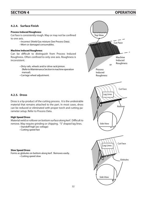
4.2.4. Surface Finish<br />
Process Induced Roughness<br />
Cut face is consistently rough. May or may not be confined<br />
to one axis.<br />
• Incorrect Shield Gas mixture (See Process Data).<br />
• Worn or damaged consumables.<br />
Top View<br />
Cut Face<br />
Machine Induced Roughness<br />
Can be difficult to distinguish from Process Induced<br />
Roughness. Often confined to only one axis. Roughness is<br />
inconsistent.<br />
• Dirty rails, wheels and/or drive rack/pinion.<br />
(Refer to Maintenance Section in machine operation<br />
manual).<br />
• Carriage wheel adjustment.<br />
Process<br />
Induced<br />
Roughness<br />
or<br />
Machine<br />
Induced<br />
Roughness<br />
Cut Face<br />
4.2.5. Dross<br />
Lag Lines<br />
Dross is a by-product of the cutting process. It is the undesirable<br />
material that remains attached to the part. In most cases, dross<br />
can be reduced or eliminated with proper torch and cutting parameter<br />
setup. Refer to Process Data.<br />
Rollover<br />
High Speed Dross<br />
Material weld or rollover on bottom surface along kerf. Difficult to<br />
remove. May require grinding or chipping. “S” shaped lag lines.<br />
• Standoff high (arc voltage)<br />
• <strong>Cutting</strong> speed fast<br />
Side View<br />
Slow Speed Dross<br />
Forms as globules on bottom along kerf. Removes easily.<br />
• <strong>Cutting</strong> speed slow<br />
Lag Lines<br />
Cut Face<br />
Globules<br />
Side View<br />
32