induSENSOR EDS, Baureihe EDS-S - Micro-Epsilon Messtechnik ...
induSENSOR EDS, Baureihe EDS-S - Micro-Epsilon Messtechnik ...
induSENSOR EDS, Baureihe EDS-S - Micro-Epsilon Messtechnik ...

You also want an ePaper? Increase the reach of your titles
YUMPU automatically turns print PDFs into web optimized ePapers that Google loves.
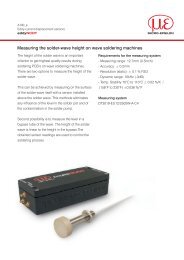
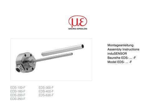
Montageanleitung<br />
Assembly Instructions<br />
<strong>induSENSOR</strong><br />
<strong>Baureihe</strong> <strong>EDS</strong>- ... -F<br />
Model <strong>EDS</strong>- ... -F<br />
<strong>EDS</strong>-100-F<br />
<strong>EDS</strong>-160-F<br />
<strong>EDS</strong>-200-F<br />
<strong>EDS</strong>-250-F<br />
<strong>EDS</strong>-300-F<br />
<strong>EDS</strong>-400-F<br />
<strong>EDS</strong>-630-F
1. Warnhinweise<br />
Schließen Sie die Spannungsversorgung nach den Sicherheitsvorschriften für elektrische Betriebsmittel an.<br />
>>Verletzungsgefahr, Beschädigung oder Zerstörung des Sensors<br />
Die Versorgungsspannung darf angegebene<br />
Grenzen nicht überschreiten. Vermeiden Sie Stöße<br />
und Schläge auf den Sensor. Biegen oder verkanten<br />
Sie nicht den Sensorstab und das Messrohr.<br />
Transportieren Sie den Sensor nicht am Sensorstab.<br />
>>Beschädigung oder Zerstörung des Sensors<br />
Sensorgehäuse<br />
Messrohr<br />
Sensorstab<br />
2.<br />
Hinweise zur CE-Kennzeichnung<br />
Für Wirbelstrom-Langwegsensoren der Serie <strong>induSENSOR</strong>, <strong>EDS</strong> mit Stromausgang gilt:<br />
EMV Richtlinie 2004/108/EG<br />
Die Sensoren erfüllen die Anforderungen gemäß den Normen<br />
DIN EN 61326-1: 2006-10 und DIN 61326-2-3: 2007-05<br />
Die Sensoren erfüllen die Anforderungen, wenn bei Installation und Betrieb die in der Betriebsanleitung beschriebenen<br />
Richtlinien eingehalten werden.<br />
3. Bestimmungsgemäßes Umfeld<br />
-- Schutzart für Sensor:<br />
-- Lagertemperatur:<br />
-40 °C bis +100 °C<br />
• Sensorstab: IP 69K<br />
-- Luftfeuchtigkeit:<br />
1<br />
• Elektronik: IP 67<br />
5 - 95 %<br />
-- Betriebstemperatur:<br />
(nicht kondensierend)<br />
-40 °C bis +85 °C, R L<br />
= 500 Ohm<br />
-- Umgebungsdruck:<br />
450*10 5 Pa (1 Pa = 1 N/m 2 ) max. 2<br />
-- EMV gemäß:<br />
DIN EN 61326-1: 2006-10<br />
DIN 61326-2-3: 2007-05<br />
1) Bei Modellen mit Steckeranschluss nur in Verbindung mit abgedichtetem Gegenstecker<br />
2) Beschränkt auf Sensorstab<br />
<strong>induSENSOR</strong>, <strong>EDS</strong>, <strong>Baureihe</strong> F<br />
Seite 2
4.<br />
Sensor<br />
housing<br />
Messprinzip<br />
Ausgangssignal (mA)<br />
20<br />
12<br />
4<br />
0 1/2 Messbereich 1/1<br />
Sensorstab<br />
Messrohr<br />
7.<br />
7.1<br />
Installation und Montage<br />
Messrohrführung und Befestigung<br />
Montieren Sie das Messrohr in der Kolbenbohrung.<br />
Die Maße für das Messrohr, siehe Abb. 4. Das Messrohr darf bei<br />
eingefahrenem Kolben den Sensorschaft nicht berühren. Beachten<br />
Sie die Messrohrposition bei Nullpunkt (= 4 mA Ausgang),<br />
siehe Abb. 2. Eine leicht exzentrische Montage des Messrohrs hat<br />
keinen negativen Einfluss auf das Sensorsignal.<br />
Befestigen Sie das Messrohr durch Pressung oder Kleben<br />
im Kolben.<br />
Eine Punktklemmung ist nicht zulässig.<br />
i<br />
Die spezifizierten technischen Daten gelten nur bei Verwendung<br />
des von MICRO-EPSILON gelieferten Messrohrs!<br />
Deutsch<br />
Abb. 1 Ausgangskennlinie eines Wirbelstrom-Langwegsensors.<br />
Dargestellte Position Messrohr: Messbereichsanfang<br />
5.<br />
Elektrischer Anschluss<br />
5-pol. Stecker, Typ CA02COM-E14S mit Bajonett-Verschluss<br />
6.<br />
Auspacken, Transport<br />
Nehmen und tragen Sie die<br />
Wirbelstrom-Langwegsensoren<br />
nicht am Sensorstab.<br />
Überprüfen Sie nach dem Auspacken<br />
die Lieferung sofort auf<br />
Vollständigkeit und Transportschäden.<br />
<strong>induSENSOR</strong>, <strong>EDS</strong>, <strong>Baureihe</strong> F<br />
a<br />
Abb. 2 Nullposition des Messrohrs<br />
Messbereich 100 160 200 250 300 400 630<br />
Maß a 20 20 20 20 20 25 25<br />
Seite 3
7.2 Sensormontage<br />
Montieren Sie den Sensor am Zylinder durch Zylinderkopfschrauben (6 x M8).<br />
Die Abdichtung erfolgt durch einen mitgelieferten O-Ring am Sensorschaft.<br />
Zylinderkopfschraube<br />
M8<br />
Sensorstab Zylinder Kolben<br />
42F7<br />
Wegsensor<br />
O-Ring<br />
Sensorschaft<br />
Messrohr<br />
Abb. 3 Sensoreinbau in einem Hydraulikzylinder<br />
Druckraumdichtung Befestigungsbohrung für Flansch: ø 42F7 Maß Toleranz<br />
O-Ring: 38x2,0 Oberfläche der Bohrung: µm<br />
Material: PUR R a<br />
= 0,8 42F7 +50<br />
R max<br />
= 3,2 +25<br />
<strong>induSENSOR</strong>, <strong>EDS</strong>, <strong>Baureihe</strong> F<br />
Seite 4
7.3<br />
Maßzeichnung<br />
ø29<br />
76,0<br />
18<br />
ø42,0 -0,05<br />
D<br />
d<br />
Sensorstab L<br />
Messrohr I<br />
59<br />
Deutsch<br />
Nut für O-Ring<br />
35,0 20,0<br />
Messbereich<br />
Sensorstab<br />
Messrohr<br />
L D I d<br />
100 140 10 140 16<br />
160 200 10 200 16<br />
200 240 10 240 16<br />
250 290 10 290 16<br />
300 340 10 340 16<br />
400 450 12 460 26<br />
630 680 12 690 26<br />
ø63,0<br />
ø80,0<br />
Abb. 4 <strong>induSENSOR</strong><br />
mit radialem Stecker,<br />
<strong>Baureihe</strong> <strong>EDS</strong>- ... -F,<br />
Abmessungen in mm,<br />
nicht maßstabsgetreu<br />
<strong>induSENSOR</strong>, <strong>EDS</strong>, <strong>Baureihe</strong> F<br />
Seite 5
7.4 Spannungsversorgung und Anzeige-/Ausgabegerät<br />
Die Spannungsversorgung und die Signalausgabe erfolgen über den 5-pol. Stecker am Elektronikgehäuse des Sensors. Pin-Belegung,<br />
siehe Abb. 5.<br />
Pin Belegung Eine 5-polige Kabelbuchse für die anwenderseitige Konfektionierung<br />
A Versorgung + (18 ... 30 VDC)<br />
eines eigenen Anschlusskabels ist im Lieferumfang enthalten.<br />
B<br />
Masse<br />
C<br />
4 ... 20 mA<br />
D<br />
Gehäuse<br />
Abb. 5 Tabelle Anschlussbelegung für 5-pol. Bajonett-Steckverbindung,<br />
Ansicht Lötseite<br />
E ---<br />
Kabelbuchse<br />
Stecker Typ CA02COM-G14S<br />
<strong>EDS</strong>-...-F<br />
A<br />
E<br />
B<br />
18...30 VDC +<br />
U B<br />
_<br />
Sensorkabel C705-5 ist als Zubehör erhältlich.<br />
<strong>EDS</strong>-...-F<br />
A<br />
18...30 VDC +<br />
E<br />
U B<br />
_<br />
B<br />
C<br />
D<br />
R<br />
L<br />
I<br />
OUT<br />
A<br />
+<br />
_<br />
C<br />
D<br />
I S<br />
R L<br />
U<br />
OUT<br />
V<br />
+<br />
_<br />
Abb. 6 Signalüberwachung mit Amperemeter<br />
R L<br />
kann optional zur Anpassung der Verlustleistung an hohe<br />
Umgebungstemperaturen eingefügt werden.<br />
<strong>induSENSOR</strong>, <strong>EDS</strong>, <strong>Baureihe</strong> F<br />
Abb. 7 Signalüberwachung mit Lastwiderstand und Voltmeter<br />
Bei der Signalüberwachung mit einem Voltmeter wird der Lastwiderstand<br />
R L<br />
abhängig von der gewünschten Ausgangsspannung<br />
U OUT<br />
dimensioniert.<br />
Berechnungsgrundlage: U OUT<br />
= R L<br />
* I Signal<br />
Seite 6
Die Sensoren werden entsprechend den Anschlussbelegungen,<br />
siehe Abb. 5 und ff., angeschlossen. Dabei sind verschiedene<br />
Kriterien zu beachten:<br />
Der maximale Lastwiderstand R L<br />
wird durch die verwendete<br />
Betriebsspannung U B<br />
begrenzt.<br />
- R L max<br />
= (U B<br />
- 10 V) / 20 mA<br />
- R L min<br />
= 82,5 * 1/V * U B<br />
- 1625 Ohm<br />
- T max<br />
= 150 °C - 3,3 °C/V * U B<br />
+ 0,04 °C/W * R L<br />
(U B<br />
- 10 V)<br />
R L max =<br />
20 mA<br />
Bei sehr kleinem Lastwiderstand wird die Sensorelektronik<br />
82,5 * U<br />
thermisch stärker belastet. Für die maximale Betriebstemperatur<br />
von 85 °C berechnet sich der minimal zulässige<br />
R = B<br />
L min<br />
- 1625 Ohm<br />
V<br />
Lastwiderstand R L<br />
zu:<br />
(Bei negativen Ergebnis: R L<br />
= 0 Ω)<br />
Bei vorgegebenen Lastwiderstand errechnet sich die<br />
3,3 * U<br />
maximal zulässige Betriebstemperatur zu:<br />
B 0,04 * R<br />
T = 150 °C - +<br />
L<br />
max<br />
V<br />
Ohm ; wobei T max<br />
≤ 85 °C<br />
R L<br />
= Lastwiderstand<br />
U B<br />
= Betriebsspannung<br />
T max<br />
= maximale Betriebstemperatur<br />
Deutsch<br />
<strong>induSENSOR</strong>, <strong>EDS</strong>, <strong>Baureihe</strong> F<br />
Seite 7
1.<br />
Warnings<br />
Connect the power supply according to the safety regulations for electrical operating equipment.<br />
>>Danger of injury, damage to or destruction of<br />
the sensor<br />
The supply voltage must not exceed specified<br />
limits. Avoid banging and knocking the sensor. Avoid bending<br />
the sensor rod or the alu tube. Do not transport the sensor on<br />
the sensor rod.<br />
>>Damage to or destruction of the sensor<br />
Sensor<br />
housing<br />
Alu tube<br />
Sensor rod<br />
2.<br />
Notes on CE Identification<br />
The following applies to <strong>EDS</strong> eddy current long stroke displacement sensors: EMC regulation 2004/108/EC<br />
The eddy current long stroke displacement sensors satisfy the requirements of the standards<br />
DIN EN 61326-1: 2006-10 and DIN 61326-2-3: 2007-05<br />
The sensors satisfy the requirements if they comply with the regulations described in the instruction manual<br />
for installation and operation.<br />
<strong>induSENSOR</strong>, <strong>EDS</strong>, model F<br />
3. Proper Invironment<br />
-- Protection class for sensor:<br />
• Sensor rod: IP 69K<br />
1<br />
• Elektronics: IP 67<br />
-- Operating temperature:<br />
-40 °C to +85 °C (-40 to 185 °F),<br />
R L<br />
= 500 Ohm<br />
-- Storage temperature:<br />
-40 °C to +100 °C<br />
(-40 to +212 °F)<br />
-- Humidity:<br />
5 - 95 %<br />
(no condensation)<br />
1) Models with male plug connection only with gasketed female plug<br />
2) Confined on sensor rod<br />
-- Ambient pressure:<br />
450*10 5 Pa (1 Pa = 1 N/m 2 ) max. 2<br />
-- EMC according to:<br />
DIN EN 61326-1: 2006-10<br />
DIN 61326-2-3: 2007-05<br />
Page 8
4.<br />
Sensor<br />
housing<br />
Measuring Principle<br />
Output signal (mA)<br />
20<br />
12<br />
4<br />
0 1/2 Measuring range 1/1<br />
Sensor rod<br />
Alu tube<br />
Fig. 1 Measuring Principle of an eddy current long stroke displacement<br />
sensor, alu tube is shown at the start of the measuring<br />
range<br />
7.<br />
7.1<br />
Installation and Assembly<br />
Measuring Tube Guide and Fastening<br />
Mount the measuring tube in the piston borehold.<br />
The dimensions for the measuring tube, see Fig. 4. When the piston<br />
is moved in the measuring tube must not touch the sensor shaft.<br />
Observe the measuring tube position at the zero point (= 4 mA output),<br />
see Fig. 2. A slightly eccentric mounting of the measuring tube<br />
has no negative influence on the sensor signal.<br />
Mount the measuring tube in the piston by means of pressing<br />
or glueing.<br />
Spot clamping is not permissable.<br />
i<br />
The specified technical data are valid only if the<br />
measuring tube is used supplied by MICRO-EPSILON!<br />
English<br />
5.<br />
Electrical Connection<br />
Connector 5-pins, CA02COM-E14S with bayonet connection<br />
6.<br />
Unpacking, Shipping<br />
Do not take and hold the sensor<br />
at the sensor rod.<br />
Check for completeness and shipping<br />
damage immediately after<br />
unpacking.<br />
a<br />
Fig. 2 Zero point of the measuring tube<br />
Measuring<br />
range<br />
Dimension a<br />
100 160 200 250 300 400 630<br />
20<br />
(0.79)<br />
20<br />
(0.79)<br />
20<br />
(0.79)<br />
20<br />
(0.79)<br />
20<br />
(0.79)<br />
25<br />
(0.98)<br />
25<br />
(0.98)<br />
<strong>induSENSOR</strong>, <strong>EDS</strong>, model F<br />
Page 9
7.2<br />
Sensor Mounting<br />
Mount the sensor in the cylinder by means of cylinder head bolts (6 x M8).<br />
The sealing is effected at the sensor shaft by means of an O-ring supplied.<br />
Cylinder head<br />
bolt M8<br />
Sensor rod Cylinder Piston<br />
42F7<br />
Displacement<br />
sensor<br />
O-ring<br />
Sensor shaft<br />
Alu tube<br />
Fig. 3 Sensor mounting in a hydraulic cylinder<br />
Sealing Diameter of the borehole: 42F7 dia. Dimension Fit tolerance<br />
O-Ring: 38x2.0 Borhole surface: µm<br />
Material: PUR R a<br />
= 0.8<br />
+50<br />
42F7<br />
R max<br />
= 3.2 +25<br />
<strong>induSENSOR</strong>, <strong>EDS</strong>, model F<br />
Page 10
7.3<br />
Dimensional Drawing<br />
ø29 (1.14 dia)<br />
18.0 (.71)<br />
76.0 (2.99)<br />
ø42.0 -0.05 (2.99 -0.002 dia.)<br />
D<br />
d<br />
Sensor rod L<br />
Alu tube I<br />
59 (2.32 )<br />
O-ring groove<br />
35.0<br />
(1.38)<br />
20.0<br />
(0.79)<br />
English<br />
Measuring<br />
range<br />
Sensor rod<br />
<strong>induSENSOR</strong>, <strong>EDS</strong>, model F<br />
Alu tube<br />
L D I d<br />
100 (3.93) 140 (5.51) 10 (0.39) 140 (5.51) 16 (0.63)<br />
160 (6.29) 200 (7.87) 10 (0.39) 200 (7.78) 16 (0.63)<br />
200 (7.87) 240 (9.45) 10 (0.39) 240 (9.45) 16 (0.63)<br />
250 (9.84) 290 (11.42) 10 (0.39) 290 (11.42) 16 (0.63)<br />
300 (11.81) 340 (13.39) 10 (0.39) 340 (13.39) 16 (0.63)<br />
400 (15.74) 450 (17.72) 12 (0.47) 460 (18.11) 26 (1.02)<br />
630 ( 24.80) 680 (26.77) 12 (0.47) 690 (27.17) 26 (1.02)<br />
ø63.0 (2.48 dia.)<br />
ø80.0 (3.15 dia.)<br />
Fig. 4 <strong>induSENSOR</strong> with<br />
radial connector, model<br />
<strong>EDS</strong>- ... -F, dimensions<br />
in mm (inches), not to<br />
scale<br />
Page 11
7.4 Power Supply and Display/Output Device<br />
Power supply and signal output are effected through the 5-contact connector on the sensor‘ s electronic housing. The pin assignment<br />
is shown, see Fig. 5.<br />
Pin Assignment A 5-pin cable socket for the user-side assembly of your own connecting<br />
A<br />
cable is part of the delivery scope.<br />
Power supply +<br />
(18 ... 30 VDC)<br />
B<br />
Ground<br />
C<br />
4 ... 20 mA<br />
D<br />
Housing<br />
Fig. 5 Table connection pin assignment, bayonet connection, view<br />
E ---<br />
of solder pin side female cable connector<br />
Connector Type CA02COM-G14S<br />
<strong>EDS</strong>-...-F<br />
A<br />
18...30 VDC +<br />
E<br />
U B<br />
_<br />
B<br />
The C705-5 sensor cable is available as an accessory.<br />
<strong>EDS</strong>-...-F<br />
A<br />
18...30 VDC +<br />
E<br />
U B<br />
_<br />
B<br />
C<br />
D<br />
R<br />
L<br />
I<br />
OUT<br />
A<br />
+<br />
_<br />
C<br />
D<br />
I S<br />
R L<br />
U<br />
OUT<br />
V<br />
+<br />
_<br />
Fig. 6 Signal monitoring with amperemeter<br />
R L<br />
can be inserted as an option for adaptation of the power<br />
loss to high ambient temperatures.<br />
Fig. 7 Signal monitoring with load resistor and voltmeter<br />
If the signal is monitored with a voltmeter the load resistor R L<br />
is<br />
dimensioned in accordance with the desired output voltage U OUT<br />
.<br />
<strong>induSENSOR</strong>, <strong>EDS</strong>, model F<br />
Formula: U OUT<br />
= R L<br />
* I Signal<br />
Page 12
The sensors are connected according to the pin assignment shown, see Fig. 5<br />
et seq. Notice the different criterias:<br />
The maximum load resistor R L<br />
is limited by the operating voltage U B<br />
.<br />
A small load resistor loads the sensor electronics more thermical. With a maximum<br />
operating temperature of 85 °C (+185 °F) the minimum load resistor R L<br />
permitted is calculated as:<br />
- R L max<br />
= (U B<br />
- 10 V) / 20 mA<br />
- R L min<br />
= 82.5 * 1/V * U B<br />
- 1625 Ohm<br />
- T max<br />
= 150 °C - 3.3 °C/V * U B<br />
+ 0.04 °C/W * R L<br />
(U B<br />
- 10 V)<br />
R L max =<br />
20 mA<br />
82.5 * U<br />
R L min = B - 1625 Ohm<br />
V<br />
(If the result is negative: R L<br />
= 0 Ω)<br />
With a preset load resistor the maximum operating temperature permitted is<br />
3.3 * U<br />
calculated as:<br />
B<br />
T max= 150 °C - +<br />
V<br />
0.04 * R L<br />
Ohm ;<br />
and T max<br />
≤ 85 °C<br />
R L<br />
= Load resistor<br />
U B<br />
= Operating voltage<br />
T max<br />
= Maximum operating temperature<br />
English<br />
<strong>induSENSOR</strong>, <strong>EDS</strong>, model F<br />
Page 13
<strong>induSENSOR</strong>, <strong>EDS</strong>, model F<br />
Page 14
English<br />
<strong>induSENSOR</strong>, <strong>EDS</strong>, model F<br />
Page 15
MICRO-EPSILON MESSTECHNIK GmbH & Co. KG<br />
Königbacher Str. 15 · 94496 Ortenburg / Deutschland<br />
Tel. +49 (0) 8542 / 168-0 · Fax +49 (0) 8542 / 168-90<br />
info@micro-epsilon.de · www.micro-epsilon.de<br />
X977X051.02-A011021HDR<br />
*X977X051.02-A01*